ANSYS Icepak User's Guide
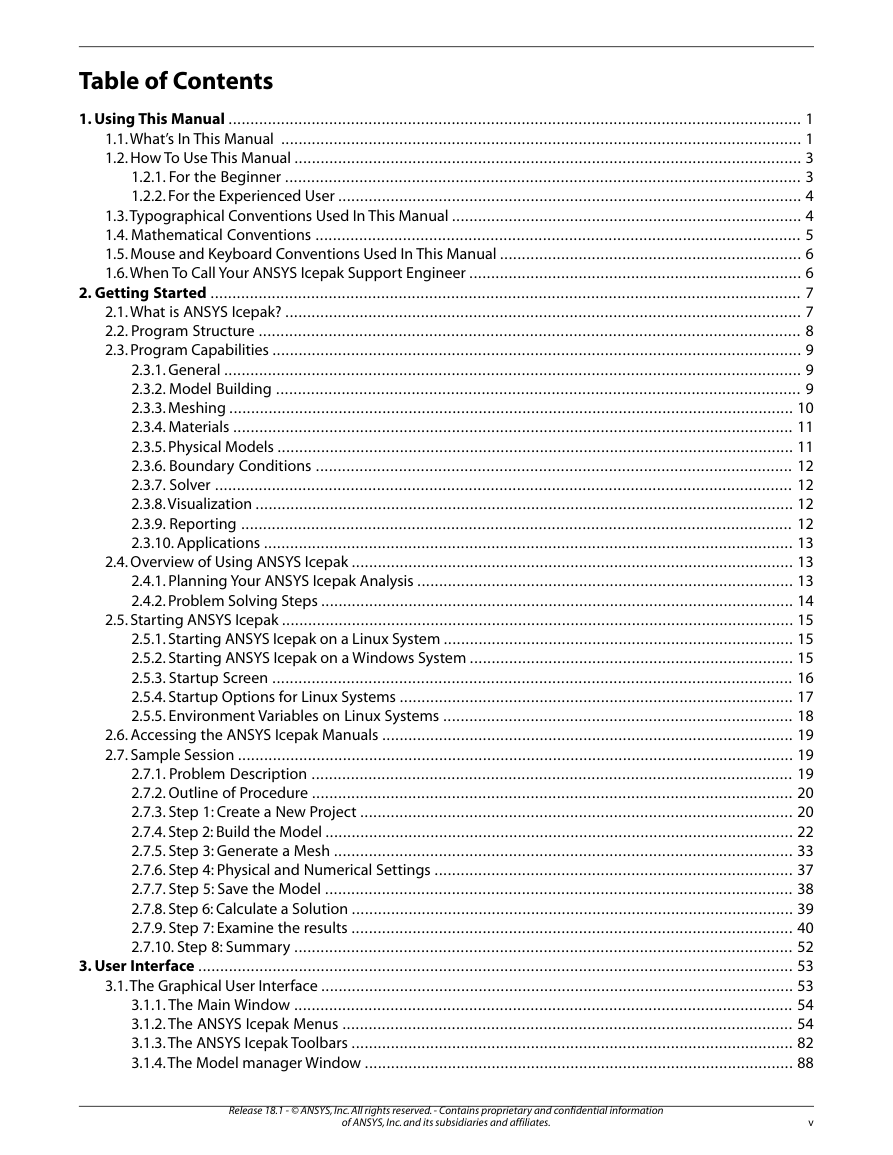
Table of Contents
Chapter 1: Using This Manual
1.1. What’s In This Manual
1.2. How To Use This Manual
1.2.1. For the Beginner
1.2.2. For the Experienced User
1.3. Typographical Conventions Used In This Manual
1.4. Mathematical Conventions
1.5. Mouse and Keyboard Conventions Used In This Manual
1.6. When To Call Your ANSYS Icepak Support Engineer
Chapter 2: Getting Started
2.1. What is ANSYS Icepak?
2.2. Program Structure
2.3. Program Capabilities
2.3.1. General
2.3.2. Model Building
2.3.3. Meshing
2.3.4. Materials
2.3.5. Physical Models
2.3.6. Boundary Conditions
2.3.7. Solver
2.3.8. Visualization
2.3.9. Reporting
2.3.10. Applications
2.4. Overview of Using ANSYS Icepak
2.4.1. Planning Your ANSYS Icepak Analysis
2.4.2. Problem Solving Steps
2.5. Starting ANSYS Icepak
2.5.1. Starting ANSYS Icepak on a Linux System
2.5.2. Starting ANSYS Icepak on a Windows System
2.5.3. Startup Screen
2.5.4. Startup Options for Linux Systems
2.5.5. Environment Variables on Linux Systems
2.6. Accessing the ANSYS Icepak Manuals
2.7. Sample Session
2.7.1. Problem Description
2.7.2. Outline of Procedure
2.7.3. Step 1: Create a New Project
2.7.4. Step 2: Build the Model
2.7.5. Step 3: Generate a Mesh
2.7.6. Step 4: Physical and Numerical Settings
2.7.7. Step 5: Save the Model
2.7.8. Step 6: Calculate a Solution
2.7.9. Step 7: Examine the results
2.7.10. Step 8: Summary
Chapter 3: User Interface
3.1. The Graphical User Interface
3.1.1. The Main Window
3.1.2. The ANSYS Icepak Menus
3.1.3. The ANSYS Icepak Toolbars
3.1.4. The Model manager Window
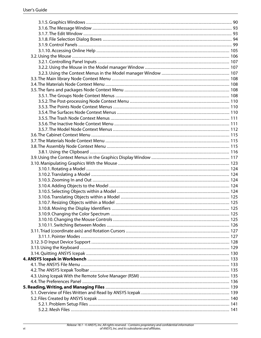
3.1.5. Graphics Windows
3.1.6. The Message Window
3.1.7. The Edit Window
3.1.8. File Selection Dialog Boxes
3.1.9. Control Panels
3.1.10. Accessing Online Help
3.2. Using the Mouse
3.2.1. Controlling Panel Inputs
3.2.2. Using the Mouse in the Model manager Window
3.2.3. Using the Context Menus in the Model manager Window
3.3. The Main library Node Context Menu
3.4. The Materials Node Context Menu
3.5. The fans and packages Node Context Menu
3.5.1. The Groups Node Context Menus
3.5.2. The Post-processing Node Context Menu
3.5.3. The Points Node Context Menus
3.5.4. The Surfaces Node Context Menus
3.5.5. The Trash Node Context Menus
3.5.6. The Inactive Node Context Menu
3.5.7. The Model Node Context Menus
3.6. The Cabinet Context Menu
3.7. The Materials Node Context Menu
3.8. The Assembly Node Context Menu
3.8.1. Using the Clipboard
3.9. Using the Context Menus in the Graphics Display Window
3.10. Manipulating Graphics With the Mouse
3.10.1. Rotating a Model
3.10.2. Translating a Model
3.10.3. Zooming In and Out
3.10.4. Adding Objects to the Model
3.10.5. Selecting Objects within a Model
3.10.6. Translating Objects within a Model
3.10.7. Resizing Objects within a Model
3.10.8. Moving the Display Identifiers
3.10.9. Changing the Color Spectrum
3.10.10. Changing the Mouse Controls
3.10.11. Switching Between Modes
3.11. Triad (coordinate axis) and Rotation Cursors
3.11.1. Pointer Modes
3.12. 3-D Input Device Support
3.13. Using the Keyboard
3.14. Quitting ANSYS Icepak
Chapter 4: ANSYS Icepak in Workbench
4.1. The ANSYS File Menu
4.2. The ANSYS Icepak Toolbar
4.3. Using Icepak With the Remote Solve Manager (RSM)
4.4. The Preferences Panel
Chapter 5: Reading, Writing, and Managing Files
5.1. Overview of Files Written and Read by ANSYS Icepak
5.2. Files Created by ANSYS Icepak
5.2.1. Problem Setup Files
5.2.2. Mesh Files
5.2.3. Solver Files
5.2.4. Optimization Files
5.2.5. Postprocessing Files
5.2.6. Metadata Files
5.3. Merging Model Data
5.3.1. Geometric Transformations
5.4. Saving a Project File
5.4.1. Recent Projects
5.5. Saving Image Files
5.5.1. Choosing the Image File Format
5.5.2. Specifying the Print Region
5.6. Packing and Unpacking Model Files
5.7. Cleaning up the Project Data
Chapter 6: Importing and Exporting Model Files
6.1. Files That Can Be Imported into ANSYS Icepak
6.2. Importing IGES, and STEP Files into ANSYS Icepak
6.2.1. How to Import IGES or STEP Files
6.2.2. Reading an IGES or STEP File into ANSYS Icepak
6.2.3. Using Families
6.2.4. Converting CAD Geometry into ANSYS Icepak Objects
6.2.5. Visibility of CAD Geometry in the Graphics Window
6.3. Importing IDF Files into ANSYS Icepak
6.3.1. Overview of Importing IDF Files into ANSYS Icepak
6.3.2. Reading an IDF File into ANSYS Icepak
6.3.3. Updating the Imported IDF File in ANSYS Icepak
6.3.4. Using the Imported IDF File in ANSYS Icepak
6.4. Importing IDX Files into ANSYS Icepak
6.4.1. Overview of Importing IDX Files into ANSYS Icepak
6.4.2. Reading an IDX File into ANSYS Icepak
6.4.3. Using the Imported IDX File in ANSYS Icepak
6.5. Importing Electronics Cooling XML Files into ANSYS Icepak
6.5.1. Importing EC XML Files
6.6. Importing Trace Files into ANSYS Icepak
6.6.1. Licensing Requirements for Importing Trace Files
6.6.2. Importing Trace Files
6.7. Trace Heating
6.7.1. Trace Heating Boundary Conditions
6.8. Importing Other Files into ANSYS Icepak
6.8.1. General Procedure
6.8.2. IGES Files
6.8.3. CSV/Excel Files
6.8.4. Networks
6.8.5. Gradient, Cadence, and Apache Sentinel Powermap Files
6.8.6. Gradient Powermap Files for Stacked Die Packages
6.8.7. Apache RedHawk Chip Thermal Model (CTM) Powermap Files
6.9. Exporting ANSYS Icepak Files
6.9.1. IGES, STEP, and Tetin Files
6.9.2. Saving an AutoTherm File
6.9.3. Write Sentinel TI HTC File
6.9.4. CSV/Excel Files
6.9.5. Networks
6.9.6. IDF Files
6.9.7. Electronics Cooling XML Files
6.9.8. Gradient, Cadence Thermal Resistance and SIwave Temperature Files
6.9.9. Write Simplorer Files
6.9.10. CFD Post/Mechanical data
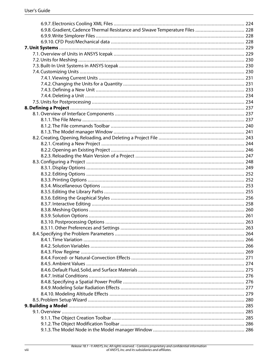
Chapter 7: Unit Systems
7.1. Overview of Units in ANSYS Icepak
7.2. Units for Meshing
7.3. Built-In Unit Systems in ANSYS Icepak
7.4. Customizing Units
7.4.1. Viewing Current Units
7.4.2. Changing the Units for a Quantity
7.4.3. Defining a New Unit
7.4.4. Deleting a Unit
7.5. Units for Postprocessing
Chapter 8: Defining a Project
8.1. Overview of Interface Components
8.1.1. The File Menu
8.1.2. The File commands Toolbar
8.1.3. The Model manager Window
8.2. Creating, Opening, Reloading, and Deleting a Project File
8.2.1. Creating a New Project
8.2.2. Opening an Existing Project
8.2.3. Reloading the Main Version of a Project
8.3. Configuring a Project
8.3.1. Display Options
8.3.2. Editing Options
8.3.3. Printing Options
8.3.4. Miscellaneous Options
8.3.5. Editing the Library Paths
8.3.6. Editing the Graphical Styles
8.3.7. Interactive Editing
8.3.8. Meshing Options
8.3.9. Solution Options
8.3.10. Postprocessing Options
8.3.11. Other Preferences and Settings
8.4. Specifying the Problem Parameters
8.4.1. Time Variation
8.4.2. Solution Variables
8.4.3. Flow Regime
8.4.4. Forced- or Natural-Convection Effects
8.4.5. Ambient Values
8.4.6. Default Fluid, Solid, and Surface Materials
8.4.7. Initial Conditions
8.4.8. Specifying a Spatial Power Profile
8.4.9. Modeling Solar Radiation Effects
8.4.10. Modeling Altitude Effects
8.5. Problem Setup Wizard
Chapter 9: Building a Model
9.1. Overview
9.1.1. The Object Creation Toolbar
9.1.2. The Object Modification Toolbar
9.1.3. The Model Node in the Model manager Window
9.1.4. The Model Menu
9.2. Defining the Cabinet
9.2.1. Resizing the Cabinet
9.2.2. Repositioning the Cabinet
9.2.3. Changing the Walls of the Cabinet
9.2.4. Changing the Name of the Cabinet
9.2.5. Modifying the Graphical Style of the Cabinet
9.3. Configuring Objects within the Cabinet
9.3.1. Overview of the Object Panels and Object Edit Windows
9.3.2. Creating a New Object
9.3.3. Selecting and Deselecting an Object
9.3.4. Editing an Object
9.3.5. Deleting an Object
9.3.6. Resizing an Object
9.3.7. Repositioning an Object
9.4. Creating a New Local Coordinate System
9.5. Editing an Existing Local Coordinate System
9.6. Viewing the Definition of a Local Coordinate System
9.7. Deleting Local Coordinate Systems
9.8. Activating and Deactivating Local Coordinate Systems
9.8.1. Aligning an Object with Another Object in the Model
9.9. Aligning Object Faces
9.10. Aligning Object Edges
9.11. Aligning Object Vertices
9.12. Aligning Object Centers
9.13. Aligning Object Face Centers
9.14. Matching Object Faces
9.15. Matching Object Edges
9.15.1. Copying an Object
9.16. Object Attributes
9.16.1. Description
9.16.2. Graphical Style
9.16.3. Position and Size
9.16.4. Geometry
9.17. Two-Dimensional Polygons
9.18. Three-Dimensional Polygons
9.18.1. Prism Objects
9.18.2. Cylindrical Objects
9.18.3. Ellipsoid Objects
9.18.4. Elliptical Cylinder Objects
9.18.5. CAD Objects
9.18.6. Physical Characteristics
9.19. Adding Objects to the Model
9.20. Grouping Objects
9.20.1. Creating a Group
9.20.2. Renaming a Group
9.20.3. Changing the Graphical Style of a Group
9.20.4. Adding Objects to a Group
9.20.5. Removing Objects From a Group
9.20.6. Copying Groups
9.20.7. Moving a Group
9.20.8. Editing the Properties of Like Objects in a Group
9.20.9. Deleting a Group
9.20.10. Activating or Deactivating a Group
9.20.11. Using a Group to Create an Assembly
9.20.12. Saving a Group as a Project
9.21. Material Properties
9.21.1. Using the Materials Library and the Materials Panel
9.21.2. Editing an Existing Material
9.21.3. Viewing the Properties of a Material
9.21.4. Copying a Material
9.21.5. Creating a New Material
9.21.6. Saving Materials and Properties
9.21.7. Deleting a Material
9.21.8. Defining Properties Using Velocity-Dependent Functions
9.21.9. Defining Properties Using Temperature-Dependent Functions
9.22. Using the Temperature value curve Window
9.23. Using the Curve specification Panel
9.24. Custom Assemblies
9.24.1. Creating and Adding an Assembly
9.24.2. Editing Properties of an Assembly
9.24.3. Assembly Viewing Options
9.24.4. Selecting an Assembly
9.24.5. Editing Objects in an Assembly
9.24.6. Copying an Assembly
9.24.7. Moving an Assembly
9.24.8. Saving an Assembly
9.24.9. Loading an Assembly
9.24.10. Merging an Assembly With Another Project
9.24.11. Deleting an Assembly
9.24.12. Expanding an Assembly Into Its Components
9.24.13. Summary Information for an Assembly
9.24.14. Total Volume of an Assembly
9.24.15. Total Area of an Assembly
9.25. Checking the Design of Your Model
9.25.1. Object and Material Summaries
9.25.2. Design Checks
Chapter 10: Networks
10.1. Location and Dimensions
10.2. Modeling IC Packages
10.3. Modeling Heat Exchangers/Cold Plates
10.4. Modeling Recirculation Openings
10.5. Network Nodes
10.6. Adding a Network to Your ANSYS Icepak Model
Chapter 11: Heat Exchangers
11.1. Geometry, Location, and Dimensions
11.2. Modeling a Planar Heat Exchanger in ANSYS Icepak
11.2.1. Modeling the Pressure Loss through a Heat Exchanger
11.2.2. Modeling the Heat Transfer through a Heat Exchanger
11.2.3. Calculating the Heat Transfer Coefficient
11.3. Adding a Heat Exchanger to Your ANSYS Icepak Model
Chapter 12: Openings
12.1. Geometry, Location, and Dimensions
12.2. Free Openings
12.3. Recirculation Openings
12.3.1. Recirculation Mass Flow Rate
12.3.2. Flow Direction for Recirculation Openings
12.3.3. Recirculation Opening Thermal Specifications
12.4. Recirculation Opening Species Filters
12.5. Adding an Opening to Your ANSYS Icepak Model
12.5.1. User Inputs for a Free Opening
12.5.2. User Inputs for a Recirculation Opening
Chapter 13: Grilles
13.1. Vents
13.2. Planar Resistances
13.3. Geometry, Location, and Dimensions
13.4. Pressure Drop Calculations for Grilles
13.5. Adding a Grille to Your ANSYS Icepak Model
13.5.1. Using the Pressure drop curve Window to Specify the Curve for a Grille
13.5.2. Using the Curve specification Panel to Specify the Pressure Drop Curve for a Grille
Chapter 14: Sources
14.1. Geometry, Location, and Dimensions
14.2. Thermal Options
14.3. Source Usage
14.4. Adding a Source to Your ANSYS Icepak Model
14.4.1. User Inputs for Thermal specification
Chapter 15: Printed Circuit Boards (PCBs)
15.1. Location and Dimensions
15.2. Types of PCBs
15.2.1. Hollow PCBs
15.2.2. Compact PCBs
15.2.3. Detailed PCBs
15.2.4. ECAD PCBs
15.3. Racks of PCBs
15.4. Adding a PCB to Your ANSYS Icepak Model
Chapter 16: Enclosures
16.1. Location and Dimensions
16.2. Adding an Enclosure to Your ANSYS Icepak Model
Chapter 17: Plates
17.1. Defining a Plate in ANSYS Icepak
17.2. Geometry, Location, and Dimensions
17.2.1. Plate Thickness
17.3. Thermal Model Type
17.4. Surface Roughness
17.5. Using Plates in Combination with Other Objects
17.6. Adding a Plate to Your ANSYS Icepak Model
17.6.1. User Inputs for the Thermal Model
17.6.2. User Inputs for the Low- and High-Side Properties of the Plate
Chapter 18: Walls
18.1. Geometry, Location, and Dimensions
18.1.1. Wall Thickness
18.2. Surface Roughness
18.3. Wall Velocity
18.4. Thermal Boundary Conditions
18.4.1. Specified Heat Flux
18.4.2. Specified Temperature
18.5. External Thermal Conditions
18.5.1. Convective Heat Transfer
18.5.2. Radiative Heat Transfer
18.6. Constructing Multifaceted Walls
18.7. Adding a Wall to Your ANSYS Icepak Model
18.7.1. User Inputs for a Symmetry Wall
18.7.2. User Inputs for a Stationary or Moving Wall
18.7.2.1. Using the Curve specification Panel to Specify a Spatial Boundary Profile
Chapter 19: Periodic Boundaries
19.1. Geometry, Location, and Dimensions
19.2. Adding a Periodic boundary to Your ANSYS Icepak Model
Chapter 20: Blocks
20.1. Geometry, Location, and Dimensions
20.2. Block Type
20.3. Surface Roughness
20.4. Physical and Thermal Specifications
20.5. Block-Combination Thermal Characteristics
20.5.1. Blocks with Coincident Surfaces
20.5.2. Blocks with Intersecting Volumes
20.6. A Block and an Intersecting Plate
20.7. Blocks Positioned on an External Wall
20.8. Cylinder, Polygon, Ellipsoid, or Elliptical Cylinder Blocks Positioned on a Prism Block
20.9. Network Blocks
20.9.1. Two-Resistor Model
20.9.2. Star Network Model
20.9.3. Fully Shunted Network Model
20.9.4. General Network Model
20.10. Adding a Block to Your ANSYS Icepak Model
20.10.1. User Inputs for the Block Surface Specification
20.10.2. User Inputs for the Block Thermal Specification
20.10.3. User Inputs for Network Blocks
Chapter 21: Fans
21.1. Defining a Fan in ANSYS Icepak
21.2. Geometry, Location, and Dimensions
21.2.1. Simple Fans
21.2.2. Fans on Solid Blocks
21.3. Flow Direction
21.4. Fans in Series
21.5. Fans in Parallel
21.6. Fans on Blocks
21.7. Specifying Swirl
21.7.1. Swirl Magnitude
21.7.2. Fan RPM
21.8. Fixed Flow
21.9. Fan Characteristic Curve
21.10. Additional Fan Options
21.10.1. Fan Efficiency
21.10.2. Fan Resistance Modeling
21.11. Adding a Fan to Your ANSYS Icepak Model
21.11.1. Using the Fan curve Window to Specify the Curve for a Characteristic Curve Fan Type
21.11.2. Using the Curve specification Panel to Specify the Curve for a Characteristic Curve Fan Type
21.11.3. Loading a Pre-Defined Fan Object
Chapter 22: Blowers
22.1. Impellers
22.2. Centrifugal Blowers
22.3. Specifying Blower Properties
22.3.1. Blower Characteristic Curve
22.3.2. Specifying Swirl
22.4. Adding a Blower to Your ANSYS Icepak Model
Chapter 23: Resistances
23.1. Geometry, Location, and Dimensions
23.2. Pressure Drop Calculation for a 3D Resistance
23.3. Adding a Resistance to Your ANSYS Icepak Model
Chapter 24: Heat Sinks
24.1. Simplified Heat Sinks
24.1.1. Modeling a Simplified Heat Sink
24.1.2. Modeling Compact Heat Sinks Using Geometry-Based Correlations
24.2. Detailed Heat Sinks
24.3. Adding a Heat Sink to Your ANSYS Icepak Model
24.3.1. User Inputs for a Simplified Heat Sink
24.3.2. User Inputs for a Detailed Heat Sink
Chapter 25: Packages
25.1. Location and Dimensions
25.2. Detailed Packages
25.2.1. Detailed Features
25.2.2. Approximated Features
25.3. Compact Conduction Model (CCM) Packages
25.3.1. Lead-Frame Packages
25.3.2. Ball Grid Array (BGA) Packages
25.4. Junction-to-Case Characterization Model
25.5. Junction-to-Board Characterization Model
25.6. Adding a Package to Your ANSYS Icepak Model
25.6.1. User Inputs for BGA Packages
25.6.2. User Inputs for Lead-Frame Packages
25.6.3. User Inputs for Stacked Die Packages
25.6.4. User Inputs for Package on Package
25.6.5. Loading a Pre-Defined Package Object
25.7. Delphi Package Characterization
Chapter 26: Transient Simulations
26.1. User Inputs for Transient Simulations
26.2. Specifying Variables as a Function of Time
26.2.1. Displaying the Variation of Transient Parameters with Time
26.2.2. Using the Time/value curve Window to Specify a Piecewise Linear Variation With Time
26.2.3. Using the Curve specification Panel to Specify a Piecewise Linear Variation With Time
26.3. Postprocessing for Transient Simulations
26.3.1. Examining Results at a Specified Time
26.3.2. Creating an Animation
26.3.3. Generating a Report
26.3.4. Creating a History Plot
Chapter 27: Species Transport Modeling
27.1. Overview of Modeling Species Transport
27.2. User Inputs for Species Transport Simulations
27.2.1. Using the Curve specification Panel to Specify a Spatial Boundary Profile
27.3. Postprocessing for Species Calculations
Chapter 28: Radiation Modeling
28.1. When to Include Radiation
28.2. Surface-to-surface Radiation Modeling
28.2.1. Radiation Modeling for Objects
28.3. User Inputs for Radiation Modeling
28.3.1. User Inputs for Specification of Radiation in Individual Object Panels
28.3.2. User Inputs for Specification of Radiation Using the Form factors Panel
28.4. Discrete Ordinates Radiation Modeling
28.5. Ray tracing Radiation Modeling
Chapter 29: Optimization
29.1. When to Use Optimization
29.2. User Inputs for Optimization
Chapter 30: Parameterizing the Model
30.1. Overview of Parameterization
30.2. Defining a Parameter in an Input Field
30.3. Defining Check Box Parameters
30.3.1. Examples
30.4. Defining Radio Button Parameters (Option Parameters)
30.5. Defining a Parameter (Design Variable) Using the Parameters and optimization Panel
30.6. Deleting Parameters
30.7. Defining Trials
30.7.1. Import and Export of Trial Data
30.7.2. Selecting Trials
30.8. Running Trials
30.8.1. Running a Single Trial
30.8.2. Running Multiple Trials
30.9. Function Reporting and Plotting
Chapter 31: State-Space Characterization
31.1. Overview
31.2. When to Use State-Space Characterization
31.3. Perform State-Space Characterization
31.4. Simplorer
Chapter 32: Krylov Reduced-order Models
32.1. Overview
32.2. When to Use Krylov ROM Simulation
32.3. Creating and Using a Krylov ROM
Chapter 33: Using Macros
33.1. JEDEC Test Chambers
33.2. Forced-Convection Test Chamber
33.3. Natural-Convection Test Chamber
33.4. Printed Circuit Board (PCB)
33.4.1. Adding a PCB to Your ANSYS Icepak Model
33.4.2. Adding PCB Attachments to Your ANSYS Icepak Model
33.5. Detailed Heat Sink
33.5.1. Adding a Detailed Heat Sink Macro to Your ANSYS Icepak Model
33.6. Heat Pipes
33.6.1. Adding a Heat Pipe to Your ANSYS Icepak Model
33.7. Data Center Components
33.7.1. CRAC macro
33.7.2. PDU Macro
33.7.3. Rack Macro
33.7.4. Tile Object
33.8. Transient Temperature Dependent Power
33.8.1. Create a Temperature-Dependent Powermap
33.8.2. Set Transient Object Properties
33.8.3. Run the Macro
33.9. Debug Divergence
33.9.1. Limitations
33.9.2. Run the Macro
33.10. TEC Macros
33.10.1. TEC
33.10.2. Run TEC
33.11. Power Dependent Power
33.11.1. Limitations
33.11.2. Set Up Target and Remote Sources
33.11.2.1. Set Up Target Sources
33.11.2.2. Set Up Remote Sources
33.11.3. Run the Macro
33.12. Create Bonding Wires
33.13. Solar Flux Calculator
Chapter 34: Power and Temperature Limit Setup
34.1. Setting Up the Power and Temperature Limit Values
34.2. Comparing the Object Temperatures with the Temperature Limits
Chapter 35: Generating a Mesh
35.1. Overview
35.2. Mesh Quality and Type
35.2.1. Mesh Quality
35.2.2. Hex-Dominant and Hexahedral Meshes
35.3. Guidelines for Mesh Generation
35.3.1. Hex-Dominant Meshing Procedure
35.3.2. Hexahedral Meshing Procedure
35.4. Creating a Minimum-Count Mesh
35.4.1. Creating a Minimum-Count Hex-Dominant Mesh
35.4.2. Creating a Minimum-Count Hexahedral Mesh
35.5. Refining the Mesh Globally
35.5.1. Global Refinement for a Hex-Dominant Mesh
35.5.2. Global Refinement for a Hexahedral Mesh
35.6. Refining the Mesh Locally
35.6.1. General Procedure
35.6.2. Definitions of Object-Specific Meshing Parameters
35.6.3. Defining Meshing Parameters for Multiple Objects
35.6.4. Meshing Parameters for Cabinets
35.6.5. Meshing Parameters for Blocks
35.6.6. Meshing Parameters for Enclosures
35.6.7. Meshing Parameters for Fans
35.6.8. Meshing Parameters for Blowers
35.6.9. Meshing Parameters for Grilles
35.6.10. Meshing Parameters for Heat Exchangers
35.6.11. Meshing Parameters for Heat Sink Objects
35.6.12. Meshing Parameters for Networks
35.6.13. Meshing Parameters for Openings
35.6.14. Meshing Parameters for Packages
35.6.15. Meshing Parameters for PCBs
35.6.16. Meshing Parameters for Plates
35.6.17. Meshing Parameters for Resistances
35.6.18. Meshing Parameters for Sources
35.6.19. Meshing Parameters for Traces
35.6.20. Meshing Parameters for Walls
35.6.21. Meshing Parameters for Assemblies
35.7. Controlling the Meshing Order for Objects
35.8. Non-Conformal Meshing Procedures for Assemblies
35.9. Displaying the Mesh
35.9.1. Displaying the Mesh on Individual Objects
35.9.2. Displaying the Mesh on a Cross-Section of the Model
35.10. Checking the Mesh
35.10.1. Checking the Face Alignment
35.10.2. Checking the Element Volume
35.10.3. Checking the Skewness
35.11. Loading an Existing Mesh
Chapter 36: Calculating a Solution
36.1. Overview
36.2. General Procedure for Setting Up and Calculating a Solution
36.3. Choosing the Discretization Scheme
36.4. Setting Under-Relaxation Factors
36.5. Selecting the Multigrid Scheme
36.6. Selecting Linear Solver Advanced Controls
36.7. Selecting the Version of the Solver
36.8. Initializing the Solution
36.9. Monitoring the Solution
36.9.1. Defining Solution Monitors
36.9.2. Plotting Residuals
36.10. Defining Postprocessing Objects
36.11. Defining Reports
36.12. Setting the Solver Controls
36.12.1. Using the Solve Panel to Set the Solver Controls
36.12.2. Advanced Solution Control Options
36.12.3. Results Solution Control Options
36.12.4. Parallel Processing
36.12.5. Optimizing the Parallel Solver Performance
36.13. Partitioning the Grid
36.13.1. Workstation Cluster
36.14. Starting Parallel ANSYS Icepak with the Job Scheduler
36.14.1. Configure Icepak for Network Parallel
36.14.1.1. Install and Configure Icepak
36.14.1.2. Installing Platform MPI
36.14.1.3. Configure Icepak Network Parallel for Microsoft 2012 Server
36.14.2. Configure Remote Linux Nodes
36.14.3. Batch Processing of ANSYS Icepak Projects on a Windows Machine
36.15. Performing Calculations
36.15.1. Starting the Calculation
36.15.2. The Solution residuals Graphics Display and Control Window
36.15.3. Changing the Solution Monitors During the Calculation
36.15.4. Ending the Calculation
36.15.5. Judging Convergence
36.16. Diagnostic Tools for Technical Support
Chapter 37: Examining the Results
37.1. Overview: The Post Menu and Postprocessing Toolbar
37.1.1. The Post Menu
37.1.2. The Postprocessing Toolbar
37.2. Graphical Displays
37.2.1. Overview of Generating Graphical Displays
37.2.2. The Significance of Color in Graphical Displays
37.2.3. Managing Postprocessing Objects
37.2.4. Displaying Results on Object Faces
37.2.5. Displaying Results on Cross-Sections of the Model
37.2.6. Displaying Results on Isosurfaces
37.2.7. Displaying Results at a Point
37.2.8. Contour Attributes
37.2.9. Vector Attributes
37.2.10. Particle Trace Attributes
37.3. XY Plots
37.3.1. Variation Plots
37.3.2. Trials Plots
37.3.3. Network Temperature Plots
37.4. Selecting a Solution Set to be Examined
37.5. Zoom-In Modeling
37.6. Display Powermap Property
Chapter 38: Generating Reports
38.1. Overview: The Report Menu
38.2. Variables Available for Reporting
38.3. HTML Reports
38.4. Reviewing a Solution
38.5. Summary Reports
38.6. Point Reports
38.7. Full Reports
38.8. Network Block Values Report
38.9. EM Heat Losses Report
38.10. Fan Operating Points Report
Chapter 39: Variables for Postprocessing and Reporting
39.1. General Information about Variables
39.2. Definitions of Variables
39.2.1. Velocity-Related Quantities
39.2.2. Pressure-Related Quantities
39.2.3. Temperature-Related Quantities
39.2.4. Radiation-Related Quantities
39.2.5. Species-Transport-Related Quantities
39.2.6. Position-Related Quantities
39.2.7. Turbulence-Related Quantities
39.2.8. Thermal Conductivity-Related Quantities
39.2.9. Joule Heating-Related Quantities
Chapter 40: Theory
40.1. Governing Equations
40.1.1. The Mass Conservation Equation
40.1.2. Momentum Equations
40.1.3. Energy Conservation Equation
40.2. Species Transport Equations
40.3. Turbulence
40.3.1. Zero-Equation Turbulence Model
40.3.2. Advanced Turbulence Models
40.4. Buoyancy-Driven Flows and Natural Convection
40.4.1. The Boussinesq Model
40.4.2. Incompressible Ideal Gas Law
40.5. Radiation
40.5.1. Overview
40.5.2. Gray-Diffuse Radiation
40.5.3. The Surface-to-Surface Radiation Model
40.5.4. The Discrete Ordinates (DO) Radiation Model
40.5.5. The Ray Tracing Radiation Model
40.6. Optimization
40.6.1. The Dynamic-Q Optimization method
40.6.2. The Dynamic-Trajectory (Leap-Frog) Optimization Method for Solving the Subproblems
40.7. Solution Procedures
40.7.1. Overview of Numerical Scheme
40.7.2. Spatial Discretization
40.7.2.1. Pseudo Transient Under-Relaxation
40.7.3. Time Discretization
40.7.4. Multigrid Method
40.7.5. Solution Residuals
40.8. Krylov ROM Theory
Bibliography
Index



 2023年江西萍乡中考道德与法治真题及答案.doc
 2012年重庆南川中考生物真题及答案.doc
 2013年江西师范大学地理学综合及文艺理论基础考研真题.doc
 2020年四川甘孜小升初语文真题及答案I卷.doc
 2020年注册岩土工程师专业基础考试真题及答案.doc
 2023-2024学年福建省厦门市九年级上学期数学月考试题及答案.doc
 2021-2022学年辽宁省沈阳市大东区九年级上学期语文期末试题及答案.doc
 2022-2023学年北京东城区初三第一学期物理期末试卷及答案.doc
 2018上半年江西教师资格初中地理学科知识与教学能力真题及答案.doc
 2012年河北国家公务员申论考试真题及答案-省级.doc
 2020-2021学年江苏省扬州市江都区邵樊片九年级上学期数学第一次质量检测试题及答案.doc
 2022下半年黑龙江教师资格证中学综合素质真题及答案.doc