IEEE TRANSACTIONS ON CIRCUITS AND SYSTEMS—I: FUNDAMENTAL THEORY AND APPLICATIONS, VOL. 48, NO. 6, JUNE 2001
699
A New Eigenfilter Based on Total Least Squares
Error Criterion
Soo-Chang Pei, Fellow, IEEE and Chien-Cheng Tseng, Member, IEEE
Abstract—In this paper, a new eigenfilter based on total least
squares error criterion is investigated. The filter coefficients are
obtained from the elements of the eigenvector corresponding to
minimum eigenvalue of a real, symmetric and positive definite ma-
trix. Four features of new method are given below. First, the com-
putation of filter coefficients of new eigenfilter is more numeri-
cally stable than that of the least-squares method whose solution
is obtained by solving matrix inverse. Second, new eigenfilter does
not need a reference frequency point for normalization as done in
traditional eigenfilter. Third, the solution of the new eigenfilter is
closer to the solution of the least-squares method than one of the
conventional eigenfilter. Fourth, the proposed method is easy to in-
corporate with linear constraints and can be extended to design
equiripple and two dimensional linear phase filters. Several design
examples are used to illustrate the effectiveness of this new design
approach.
Index
least-squares criterion.
Terms—Eigenfilter,
least-squares
design,
total
I. INTRODUCTION
McClellan–Parks–Rabiner
C ONVENTIONALLY, we often use the well-known
(MPR) computer program
and standard linear programming technique to design linear
phase finite impulse respones (FIR) filters according to the
Chebyshev criterion which minimizes the maximum error in
frequency response [1], [2]. The minimax designs usually give
the designers a smallest length filter for a given specification.
However, it is difficult for the MPR algorithm to incorporate
both a time- and frequency-domain constraint. And, linear
programming technique needs a large memory space and con-
siderable computation time. Thus, a number of researchers have
considered linear phase FIR filter design using least-squares
optimality criterion.
From literature survey, two well-documented least squares
approaches for FIR filter designs are inverse matrix (IM) method
and eigen-approach. References [3]–[8] are examples of publi-
cations which include descriptions of using two methods to de-
sign various filters. The IM methods are based on solving a set of
linear simultaneous equations by matrix inversion [3], [4], and
the eigen-approaches are based on the computation of an eigen-
vector of an appropriate real, symmetric, and positive-definite
matrix [5]–[8]. Compared with minimax design, the advantage
Manuscript received February 24, 2000; revised November 15, 2000. This
paper was recommended by Associate Editor P. P. Vaidyanathan.
S.-C. Pei is with the Department of Electrical Engineering, National Taiwan
University, Taipei, Taiwan, R.O.C.
C.-C. Tseng is with the Department of Computer and Communication Engi-
neering, National Kaohsiung First University of Science and Technology, Kaoh-
siung, Taiwan, R.O.C.
Publisher Item Identifier S 1057-7122(01)04289-1.
of least squares design is that it is easy to add constraints and it
requires simple computation. So far, least squares approach has
been widely used to design various filters in multirate applica-
tions and image processing [9], [10].
The purpose of this paper is to design linear phase FIR filters
using total least squares (TLS) error criterion which has been
successfully used to solve many engineering problems such
as acoustic radiation problem, adaptive filtering, beamformer
and harmonic retrieval etc., [11]–[13]. The filter coefficients
based on TLS criterion are obtained from the elements of the
eigenvector corresponding to minimum eigenvalue of a real,
symmetric and positive definite matrix. Due to this, the total
least squares filter design is referred to as the new eigenfilter
approach. The main difference between conventional and
new eigenfilters is that conventional method needs to specify
the reference point in frequency domain, but new approach
does not require this. Moreover,
three unique features of
new eigenfilter are as follows. First, the computation of filter
coefficients of new eigenfilter is more numerically stable
than the least-squares method whose solution is obtained by
solving IM. Second, the solution of the new eigenfilter is
closer to the solution of the least-squares method than one
of the conventional eigenfilter. Third, it is easy for the new
eigenfilter to incorporate time domain constraints and other
linear constraints as for the traditional eigenfilter. Moreover,
the new eigenfilter can be extended to design equiripple and
two dimensional linear phase filters.
The paper is organized as follows. In Section II, the linear
phase FIR filter designs using conventional IM method and
eigen-approach are briefly reviewed. In Section III, a new
eigenfilter based on total least squares error criterion is devel-
oped. In Section IV, we extend the new eigenfilter approach to
design FIR filters in conjunction with general linear constraints.
The notch filter with controlled null width is presented to show
the effectiveness of our method. In Section V, we use iterative
weighted total least squares method to design equiripple linear
phase FIR filters. Finally, the new eigen-approach is modified
to design two dimensional quadrantally symmetric FIR filters
and concluding remarks are made.
II. CONVENTIONAL LEAST SQUARES FILTER DESIGN
A. Problem Statement
A causal
-th order FIR filter can be represented as
(1)
1057–7122/01$10.00 © 2001 IEEE
�
700
IEEE TRANSACTIONS ON CIRCUITS AND SYSTEMS—I: FUNDAMENTAL THEORY AND APPLICATIONS, VOL. 48, NO. 6, JUNE 2001
This filter is said to have linear phase if phase response is linear
is even or odd, and
in frequency. Depending on whether
is symmetric or antisymmetric, we obtain four
whether
types of real coefficient linear phase filters [2]. The magnitude
responses of these four types of filters can be expressed as
Because
is a positive-definite, real, and symmetric matrix,
the simultaneous linear equations can be solved by a compu-
tationally efficient method, like Cholesky decomposition [16].
Several interesting design examples of such a least squares FIR
filters can be found in [3].
(2)
where
The coefficient
filter, whereas
the column vector
is an appropriate trigonometrical function.
is related to the impulse response of the
. Defining
is a function of the filter order
and
then we rewrite (2) as
(3)
(4)
C. Conventional Eigenfilter Design
In the following, we will design linear phase FIR filter using
another least squares error measure. The solution in this case is
the eigenvector corresponding to the minimum eigenvalue of a
real, symmetric, and positive definite matrix so that it is often
referred to as eigenfilter approach in the literature. So far, eigen-
filter approach has been used to design various types of filters
such as lowpass filters, differentiators and Hilbert transformers
[5]–[7]. The design procedure of these eigenfilters can be sum-
marized a unified formulation as follows.
Step 1: Choose the reference point
satisfying
. Some consideration of this choice can be found in
[5]–[7].
(5)
Step 2: Make magnitude response
specification
approximation, we find the optimal solution
minimizing the following quadratic error measure
approximate the
. To achieve this
by
The notation denotes the vector or matrix transpose. Now, the
such that the magnitude response
problem is how we can find
as well
as possible. Various least squares error measures will be used
through this paper.
in (5) fits the desired magnitude response
B. Conventional Least Squares Filter Design
Using (5), we can rewrite
as
The conventional
least squares approach corresponds to
minimizing the following objective function [Tufts and Francis,
1970]
(6)
, but excluding the transition
where matrix
where
band. The matrix
is the region
, vector
, and scalar
are
(11)
(12)
(13)
is a quadratic function of
Because
must satisfy
that minimizes
is the multivariable derivative of
Therefore, the optimal solution
(7)
, the optimal value
0, where
. From (6)
(8)
(9)
The actual value of
solving simultaneous linear equations
can be obtained by matrix inversion or by
(10)
is a real, symmetric and positive-def-
oc-
. To avoid trivial solutions, the con-
1 is added. Under this condition, the
Note that
inite matrix. Obviously, the minimum of
curs at
straint
solution vector
corresponding to its minimum eigenvalue in view of
the well-known Rayleigh’s principle [14].
is simply the eigenvector of
Step 3: Since we
have made
approximate
, we should scale the so-
lution
[5]–[7]. Thus, the final solution is given by
properly to satisfy
(14)
For eigenfilter design, we are interested in only the
minimum eigenvector of a symmetric matrix, this
computation can be performed efficiently by the
conjugate gradient method [15], or iterative power
method [16].
�
PEI AND TSENG: A NEW EIGENFILTER BASED ON TOTAL LEAST SQUARES ERROR CRITERION
701
The least squares filter design problem means that the optimal
filter weight
is obtained by minimizing the squared errors
(18)
is the region
, but excluding the transition
where
band. Now, two types of least squares errors will be investigated
in detail. Substituting (16) into (18), we obtain
which is same as the (6). Thus, this least squares error measure is
equal to the conventional one. Next, substituting (17) into (18),
we have
where
and
are given by
(19)
(20)
occurs at
Based on Rayleigh’s principle, the minimum of
corresponding to the minimum
the eigenvector of the matrix
is also a real, symmetric and pos-
eigenvalue. Note that the
is simply the
itive definite matrix. Since the solution vector
, we call this least squares
minimum eigenvector of matrix
design as new eigenfilter design. In [11], the least squares error
of type 2 is named as total least squares error which have been
successfully used to solve many engineering problems such as
acoustic radiation problem, beamformer, structural identifica-
tion and harmonic retrieval etc. We claim that the new eigenfilter
is optimal in total least squares error sense. Now, we summarize
the design procedure of new eigenfilter as follows.
Step 1: Compute the matrix
Step 2: Calculate the minimum eigenvector
.
.
Step 3: Normalize the solution vector
. The final desired solution
of the matrix
to the form
is equal to
.
Three main differences between conventional eigenfilter and
new eigenfilter are listed below. First, conventional eigenfilter
needs to specify the reference point, but new eigenfilter does
of
not require this choice. Second, the size of the matrix
, but the size of the matrix
conventional eigenfilter is
. Third, the normal-
ization of conventional eigenfilter is to scale minimum eigen-
, but the normalization of
vector
to the
new eigenfilter is to scale minimum eigenvector vector
form
of new eigenfilter is
to satisfy
.
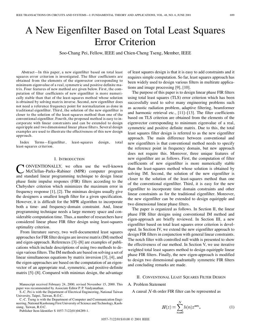
Fig. 1. Geometric interpretation of two error measures at frequency ! = �
(a) Type 1 error. (b) Type 2 error.
III. A NEW EIGENFILTER BASED ON TOTAL LEAST SQUARES
ERROR CRITERION
A. A New Eigenfilter Design
The well-known linear phase filter design problem is to find
such that the desired magnitude response
a filter weight
is equal to the actual magnitude response
i.e.,
of the filter,
(15)
for each
generated by
. In the space
, it is clear that the expression
a hyperplane. For a given frequency , the
notes a point in
stated as “we want the point
perplane
and
denotes
de-
. Now, the filter design problem can be re-
to fall on the hy-
.” When the point
, the
error between them can be measured in several ways. Two typ-
ical ones with geometric interpretation are shown in Fig. 1. One
error (type 1) is given by
does not fall on the plane
for all
the other (type 2) is given by
(16)
(17)
�
702
IEEE TRANSACTIONS ON CIRCUITS AND SYSTEMS—I: FUNDAMENTAL THEORY AND APPLICATIONS, VOL. 48, NO. 6, JUNE 2001
B. A Unified Design Procedure
In the following, we first study the relation between
,
and
. Then, we develop a unified design procedure to obtain
the solutions of three least squares approaches at the same time.
and the matrix
Fact 1: The relation between the matrix
is given by:
Proof: From (13), we have
(21)
(22)
Substituting (7) into (22), we obtain (21). The proof is com-
pleted.
Fact 2: The relation between the matrix
and the matrix
is given by
Proof: From (20), we have
(23)
(24)
Substituting (7) into (24), we obtain (23). The proof is com-
pleted.
Although the above two facts are not concerned with the per-
formance of designed filters, they provide us a way to program
three least squares methods in a unified procedure as follows.
Step 1: Calculate matrix
. The elements of
are given
by
Step 2: Compute vector whose elements can be written as
Step 3: Find the solution of conventional least squares filter
design, i.e.,
.
Step 4: Use fact 1 to calculate matrix
Step 5: Find the minimum eigenvector
.
of matrix
.
And, the solution of eigenfilter is given by
.
Step 6: Use fact 2 to calculate matrix
Step 7: Find the minimum eigenvector
.
And, normalize the solution vector
of matrix
.
to the form
. The final solution
is written as
.
C. Design Example
In the example, we will compare the performance of three
least squares methods. This example is performed with the
MATLAB Language in an IBM PC compatible computer by
using the unified design procedure.
Example 1: Lowpass Filter Design: Consider the problem of
designing a lowpass filter with the following desired amplitude
response
don't care
(25)
There are four cases of FIR filters with exactly linear phase, but
only two of these could be applied to design lowpass filters, that
is, case 1 and case 2 [2]. Here, we only consider case 1 filter
whose elements of matrix
are given by
and
[0,
. Now, two experiments
where the region
chosen in the conventional
are made. The reference point
. The least squares solution is obtained using
eigenfilter is
“inv.m” of MATLAB, and eigenfilters are designed using
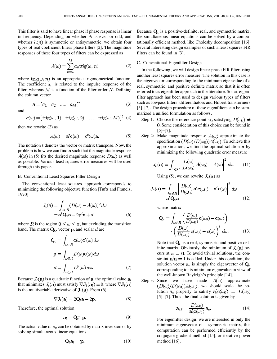
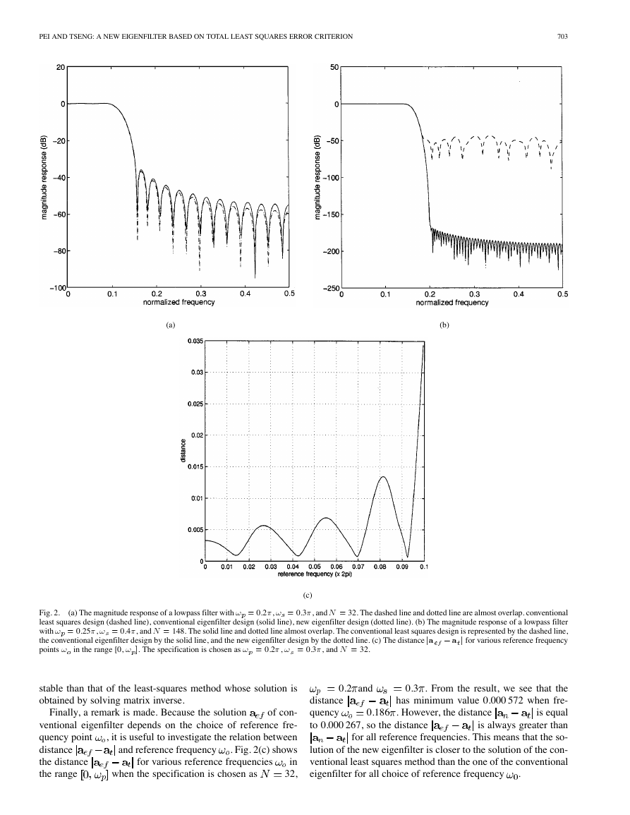
“eig.m.” First, Fig. 2(a) shows the magnitude responses of
0.2 ,
three least squares approaches with order
0.3 . From this result, it is clear that the specification
and
are well satisfied for three least squares methods. However,
the stopband attenuation of conventional eigenfilter is slightly
worse than the other two methods, because the amplitude
response at the reference frequency must be satisfied exactly
for the conventional eigenfilter design. Moreover, the distances
between the solutions of three methods are listed as follows:
32,
Thus, the solution of the new eigenfilter is closer to the solu-
tion of the conventional least squares method than the one of
the conventional eigenfilter. Second, we consider the design of
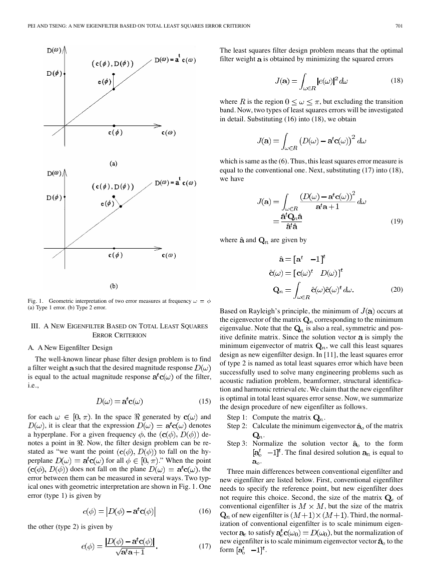
high order filters with large transition band. Fig. 2(b) shows the
148,
magnitude responses of three approaches with order
0.4 . It is clear that the design results of
least squares method is very bad in the stopband, but two eigen-
filter approaches still work well. This is due to ill conditioning of
. Thus, the computa-
matrix
tion of filter coefficients of new eigenfilter is more numerically
whose determinant is 6 10
0.25 , and
�
PEI AND TSENG: A NEW EIGENFILTER BASED ON TOTAL LEAST SQUARES ERROR CRITERION
703
(a)
(b)
(a) The magnitude response of a lowpass filter with ! = 0.2�, ! = 0.3�, and N = 32. The dashed line and dotted line are almost overlap. conventional
Fig. 2.
least squares design (dashed line), conventional eigenfilter design (solid line), new eigenfilter design (dotted line). (b) The magnitude response of a lowpass filter
with ! = 0.25�, ! = 0.4�, and N = 148. The solid line and dotted line almost overlap. The conventional least squares design is represented by the dashed line,
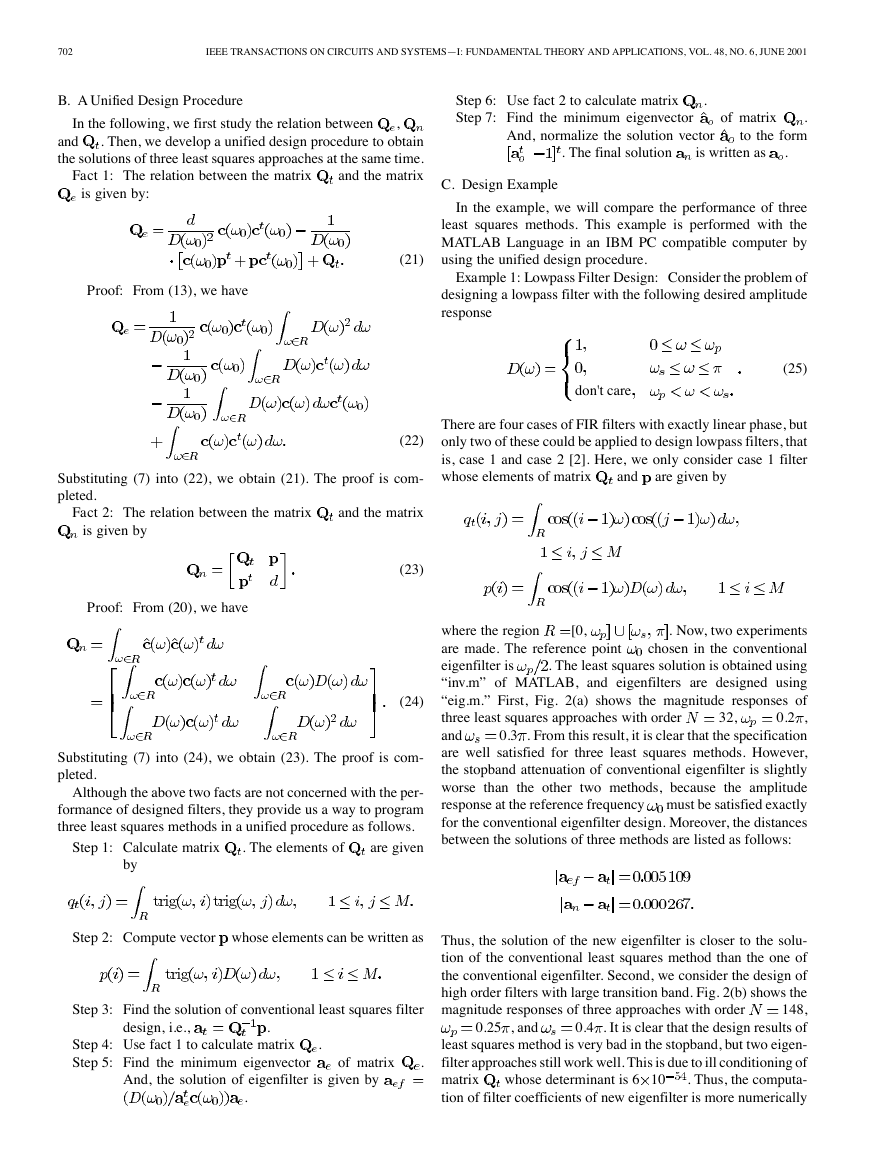
the conventional eigenfilter design by the solid line, and the new eigenfilter design by the dotted line. (c) The distance ja � a j for various reference frequency
points ! in the range [0, ! ]. The specification is chosen as ! = 0.2�, ! = 0.3�, and N = 32.
(c)
stable than that of the least-squares method whose solution is
obtained by solving matrix inverse.
Finally, a remark is made. Because the solution
of con-
ventional eigenfilter depends on the choice of reference fre-
, it is useful to investigate the relation between
quency point
. Fig. 2(c) shows
distance
in
the distance
32,
the range
when the specification is chosen as
for various reference frequencies
and reference frequency
0.2 and
0.186 . However, the distance
distance
quency
to 0.000 267, so the distance
0.3 . From the result, we see that the
has minimum value 0.000 572 when fre-
is equal
is always greater than
for all reference frequencies. This means that the so-
lution of the new eigenfilter is closer to the solution of the con-
ventional least squares method than the one of the conventional
eigenfilter for all choice of reference frequency
.
�
704
IEEE TRANSACTIONS ON CIRCUITS AND SYSTEMS—I: FUNDAMENTAL THEORY AND APPLICATIONS, VOL. 48, NO. 6, JUNE 2001
IV. NEW EIGENFILTER DESIGN WITH LINEAR CONSTRAINT
The main advantage of the least squares approach is that var-
ious time and frequency constraints can be incorporated. In the
linear case, the general form of the constraints can be stated as
to find the orthonormal basis of null space of matrix
the following two facts will help us to solve it [16].
. Any of
Fact 3: Let singular value decomposition (SVD) [14] of ma-
trix
be
(26)
where unitary matrices
and diagonal matrix
are
(29)
is an
vector. Note that
matrix and is an
. Moreover, we assume
where
is the number of the linear constraints which is usually smaller
is
than the number of coefficients
a full rank matrix in order to avoid redundant constraints. For
the conventional least squares filter design, the closed-form so-
lution can be obtained by using the well-known Lagrange mul-
tiplier method [17]. Moreover, the procedure to find the solu-
tion of the conventional constrained eigenfilter design is slightly
complicated, the detail can be found in [5], [18]. As to the new
eigenfilter design which is our main focus, the design problem
becomes
Minimize
Subject to
where
to rewrite the constraint
. The basic idea of solving this problem is
as the following form:
where
. Then, the problem is reduced to
Minimize
Subject to
(27)
(28)
satisfying
, where the
form an orthonormal basis of the null space of
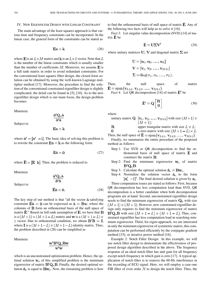
The key step of our method is that “all the vector
constraint
columns of
matrix .” Based on full rank assumption of
is a
can be expressed as
, we have that
matrix and
is a
vector. Due to orthonormal condition, we obtain
,
identity matrix. Thus,
is a
where
the problem described in (28) can be simplified as
Then,
the
null
space
.
of
matrix
Fact 4: Let QR decomposition [14] of matrix
be
(30)
where
unitary matrix
with size
;
upper triangular matrix with size
a zero matrix with size
;
.
Then, the null space of
.
Finally, we summarize the entire procedure of the proposed
method as follows:
Step 1: Use SVD or QR decomposition to find the or-
and
thonormal basis of null space of matrix
construct the matrix
.
Step 2: Find the minimum eigenvector
of matrix
.
.
Step 3: Calculate the optimal solution
Step 4: Normalize the solution vector
. The final desired solution is given by
to the form
.
Three computation issues are stated as follows: First, because
QR decomposition has less computation load than SVD, QR
decomposition is a better candidate when both decomposition
programs are at hand. Second, unconstrained eigenfilter design
with size
needs to find the minimum eigenvector of matrix
. However, new constrained eigenfilter de-
sign only requires to find the minimum eigenvector of matrix
. Thus, con-
strained eigenfilter has less computation load in searching min-
imum eigenvector. Third, for eigen-approach, we are interested
in only the minimum eigenvector of symmetric matrix, this com-
putation can be performed efficiently by the conjugate gradient
method [15], or iterative power method [16].
with size
Minimize
which is an unconstrained optimization problem. Hence, the op-
of this simplified problem is the minimum
timal solution
. Finally, the desired optimal so-
eigenvector of matrix
. Now, the remaining problem is how
lution
is equal to
Example 2: Notch Filter Design: In this example, we will
use notch filter design to demonstrate the effectiveness of pro-
posed design algorithm described in the above. The frequency
response of an ideal notch filter has unit gain for all frequency
except notch frequency in which gain is zero [17]. A typical ap-
plication of notch filter is to remove the 60-Hz interference in
the recording of ECG signal. Here, we will employ a case-one
to design the notch filter. Thus, the
FIR filter of even order
�
PEI AND TSENG: A NEW EIGENFILTER BASED ON TOTAL LEAST SQUARES ERROR CRITERION
705
(a)
(b)
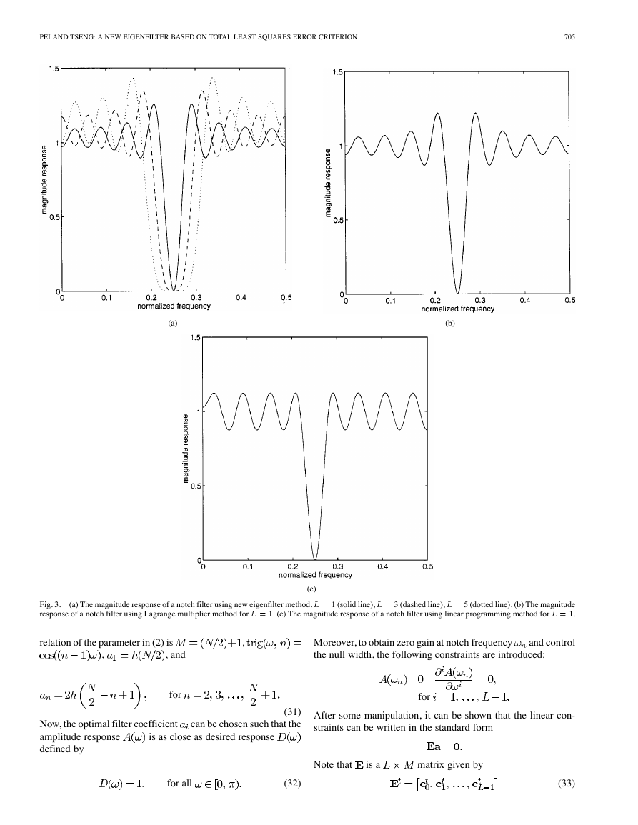
(a) The magnitude response of a notch filter using new eigenfilter method. L = 1 (solid line), L = 3 (dashed line), L = 5 (dotted line). (b) The magnitude
Fig. 3.
response of a notch filter using Lagrange multiplier method for L = 1. (c) The magnitude response of a notch filter using linear programming method for L = 1.
(c)
relation of the parameter in (2) is
,
,
, and
for
Now, the optimal filter coefficient
amplitude response
defined by
(31)
can be chosen such that the
is as close as desired response
Moreover, to obtain zero gain at notch frequency
the null width, the following constraints are introduced:
and control
for
After some manipulation, it can be shown that the linear con-
straints can be written in the standard form
for all
(32)
(33)
Note that
is a
matrix given by
�
706
IEEE TRANSACTIONS ON CIRCUITS AND SYSTEMS—I: FUNDAMENTAL THEORY AND APPLICATIONS, VOL. 48, NO. 6, JUNE 2001
where vectors
0.5 ,
32, and various
So far, the linear constraints of notch filter design has been for-
mulated as standard form. Now, let us see some numerical ex-
amples. Fig. 3(a) shows the magnitude response of a notch filter
.
using proposed method for
It is clear that the frequency response is satisfactory. When the
increases, the notch width increases
number of constraints
accordingly. For comparison, Fig. 3(b) and (c) show the magni-
tude responses of a notch filter using the well-known Lagrange
multiplier and linear programming methods for
0.5 , and
1. Basically, the linear programming method is
a minimax design and Lagrange multiplier approach is a con-
ventional least squares design. From this result, it is obvious
that proposed method almost has the same frequency response
as Lagrange multiplier method. This is due to the fact that both
of these methods are based on the least squares criterion. Com-
pared with equiripple design using linear programming method,
the new eigenfilter method has better frequency response fitting
for all frequency band except at the range around the notch fre-
quency
32,
.
V. A NEW EQUIRIPPLE EIGENFILTER DESIGN
In the literature, it has been reported that the weighted
least squares technique will produce an equiripple design if a
suitable least squares frequency response weighting function is
used [19]–[21]. For the conventional least squares filter design,
several novel iterative algorithms for deriving the weighting
function have been developed such as Lawson’s algorithm
and Lim’s method [19]. On the other hand, the amplitude re-
sponse of conventional eigenfilter can be made approximately
equiripple by employing the similar iterative techniques [5]. In
this section, we will present an approach to design equiripple
eigenfilter based on weighted total least squares error criterion.
From (17), the weighted total least squares error can be written
as
of the matrix
and scale it to the form
Based on Rayleigh’s principle, we find the minimum eigen-
vector
, then
is the desired optimum solution. Although optimum solution
can be obtained for any given least squares weighting function,
there is no known analytical method for deriving the weighting
which will produce an equiripple design. Hence,
function
is the weighting
an iterative procedure is adopted. If
function used in the th iteration, then the weighting function
used in the
th iteration may be expressed as
where
is given by
(36)
(37)
th iteration,
is the amplitude response at
The
is the envelope of the argument function which is formed by
joining together all the extremal points of the error function
using straight lines (see [19, Fig. 3]), and
affects the convergence and convergent speed
the parameter
[19]. Once the errors become equiripple, the weighting func-
tion does not alter anymore with further iteration. If we define
, then the stop
and
criterion is given by
(38)
where
overall design procedure can be summarized as follows:
is a small positive number (say 0.02). Finally, the
Step 1: Specify the initial weighting function as uniform
weighting, i.e.,
for
(39)
Step 2: Use (35) to obtain optimal solution of filter coef-
and calculate initial amplitude response
ficients
and function
. Let
0.
Step 3: Use (36), (37) to compute new weighting function
.
Step 4: Use (35) to obtain optimal solution of filter coef-
and calculate new amplitude response
and function
ficients
.
where
and
are given by
Step 5: Use (38) to check whether the errors are equiripple.
If equiripple design is achieved, then stop iteration.
Otherwise, let
and go to Step 3.
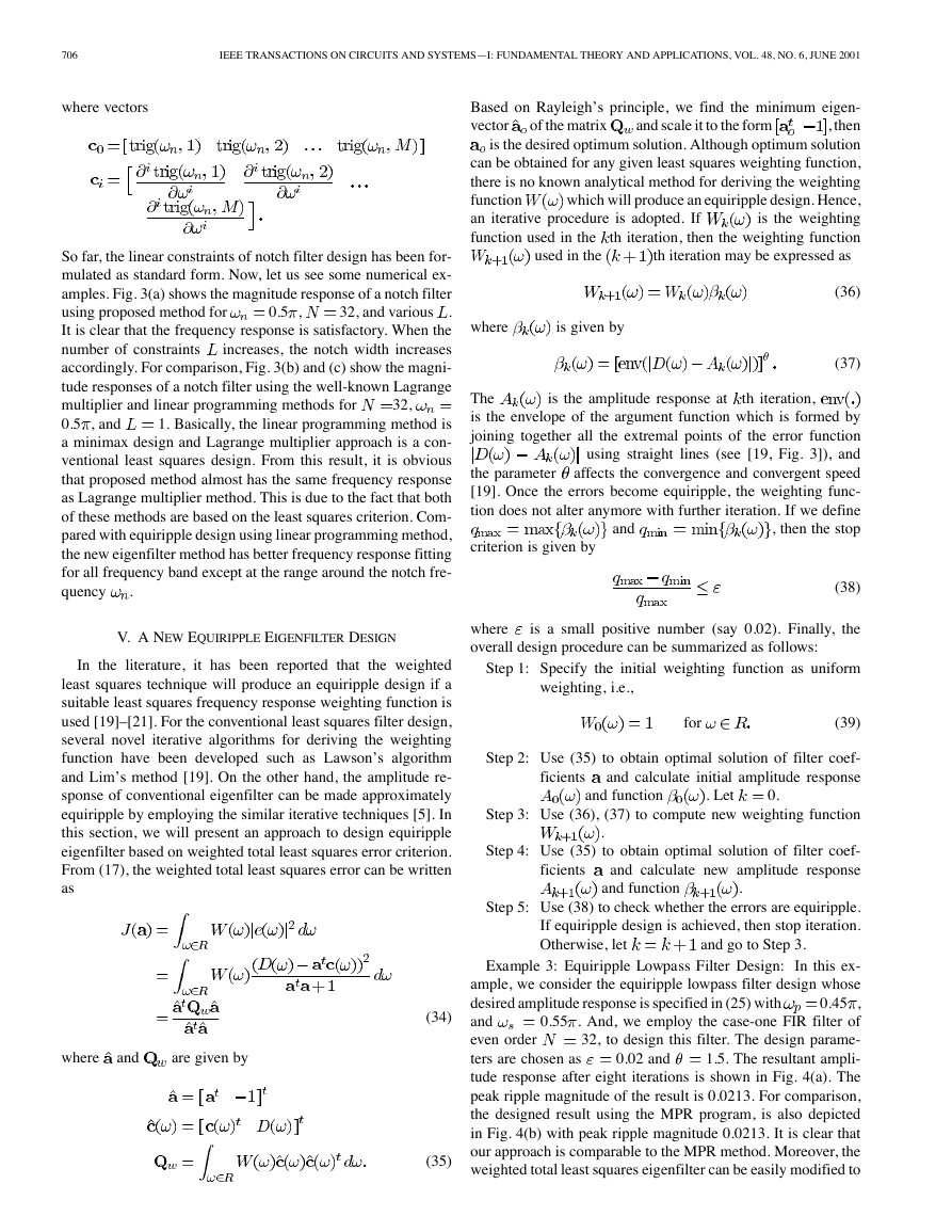
Example 3: Equiripple Lowpass Filter Design: In this ex-
ample, we consider the equiripple lowpass filter design whose
0.45 ,
desired amplitude response is specified in (25) with
0.55 . And, we employ the case-one FIR filter of
and
32, to design this filter. The design parame-
even order
1.5. The resultant ampli-
ters are chosen as
tude response after eight iterations is shown in Fig. 4(a). The
peak ripple magnitude of the result is 0.0213. For comparison,
the designed result using the MPR program, is also depicted
in Fig. 4(b) with peak ripple magnitude 0.0213. It is clear that
our approach is comparable to the MPR method. Moreover, the
weighted total least squares eigenfilter can be easily modified to
0.02 and
(34)
(35)
�


 2023年江西萍乡中考道德与法治真题及答案.doc
 2012年重庆南川中考生物真题及答案.doc
 2013年江西师范大学地理学综合及文艺理论基础考研真题.doc
 2020年四川甘孜小升初语文真题及答案I卷.doc
 2020年注册岩土工程师专业基础考试真题及答案.doc
 2023-2024学年福建省厦门市九年级上学期数学月考试题及答案.doc
 2021-2022学年辽宁省沈阳市大东区九年级上学期语文期末试题及答案.doc
 2022-2023学年北京东城区初三第一学期物理期末试卷及答案.doc
 2018上半年江西教师资格初中地理学科知识与教学能力真题及答案.doc
 2012年河北国家公务员申论考试真题及答案-省级.doc
 2020-2021学年江苏省扬州市江都区邵樊片九年级上学期数学第一次质量检测试题及答案.doc
 2022下半年黑龙江教师资格证中学综合素质真题及答案.doc