Chapter 2
Dynamic Models
Problems and Solutions for Section 2.1
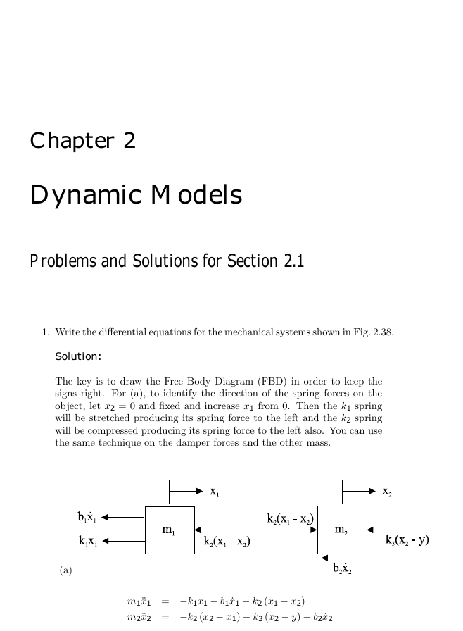
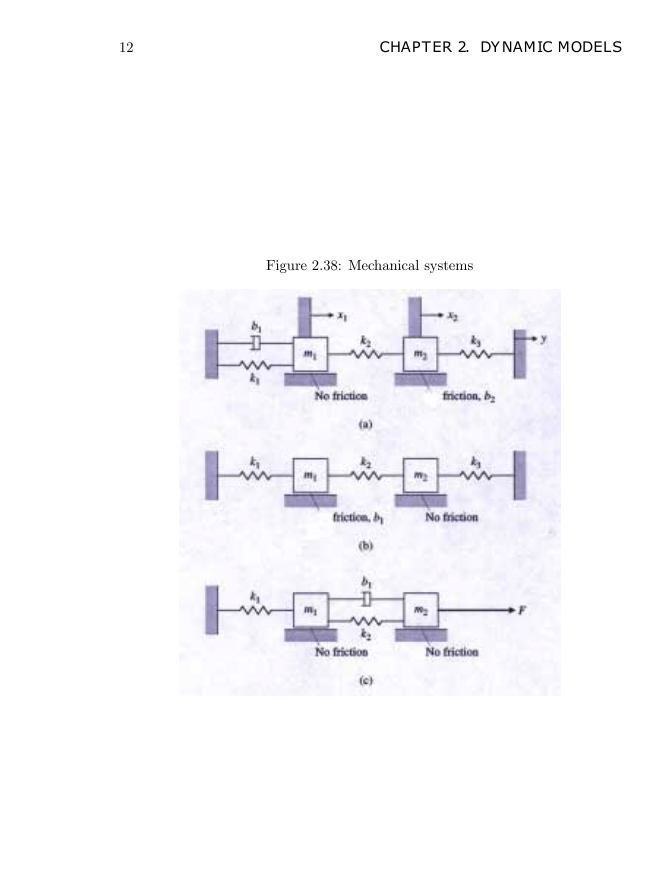
1. Write the differential equations for the mechanical systems shown in Fig. 2.38.
Solution:
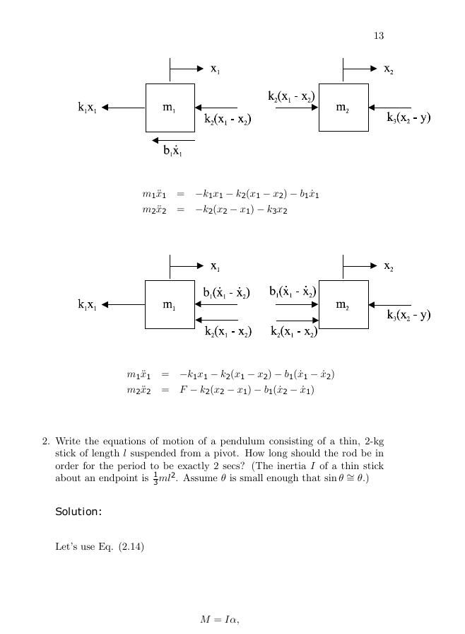
The key is to draw the Free Body Diagram (FBD) in order to keep the
signs right. For (a), to identify the direction of the spring forces on the
object, let x2 = 0 and xed and increase x1 from 0. Then the k1 spring
will be stretched producing its spring force to the left and the k2 spring
will be compressed producing its spring force to the left also. You can use
the same technique on the damper forces and the other mass.
(a)
m1 ¤x1 = −k1x1 − b1 œx1 − k2 (x1 − x2)
m2 ¤x2 = −k2 (x2 − x1) − k3 (x2 − y) − b2 œx2
�
12
CHAPTER 2. DYNAMIC MODELS
Figure 2.38: Mechanical systems
�
13
m1 ¤x1 = −k1x1 − k2(x1 − x2) − b1 œx1
m2 ¤x2 = −k2(x2 − x1) − k3x2
m1 ¤x1 = −k1x1 − k2(x1 − x2) − b1( œx1 − œx2)
m2 ¤x2 = F − k2(x2 − x1) − b1( œx2 − œx1)
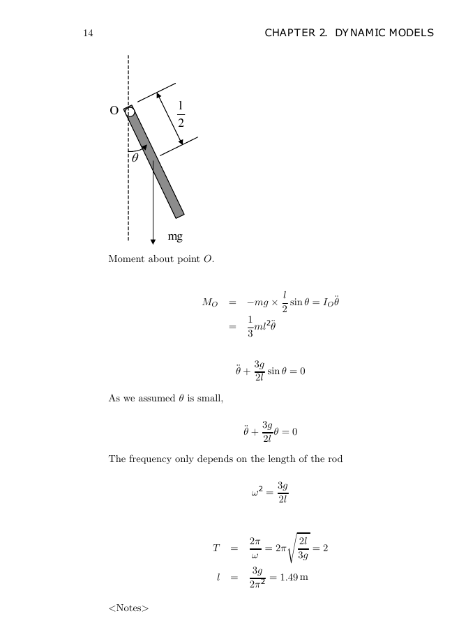
2. Write the equations of motion of a pendulum consisting of a thin, 2-kg
stick of length l suspended from a pivot. How long should the rod be in
order for the period to be exactly 2 secs? (The inertia I of a thin stick
about an endpoint is 1
3 ml2. Assume θ is small enough that sin θ ∼= θ.)
Solution:
Lets use Eq. (2.14)
M = Iα,
�
14
CHAPTER 2. DYNAMIC MODELS
O
G
l
2
mg
Moment about point O.
l
2
sin θ = IO¤θ
MO = −mg
ml2¤θ
=
1
3
As we assumed θ is small,
¤θ +
3g
2l
sin θ = 0
¤θ +
3g
2l
θ = 0
The frequency only depends on the length of the rod
ω2 =
3g
2l
T =
l =
= 2πs 2l
3g
2π
ω
3g
2π2 = 1.49 m
= 2
�
�
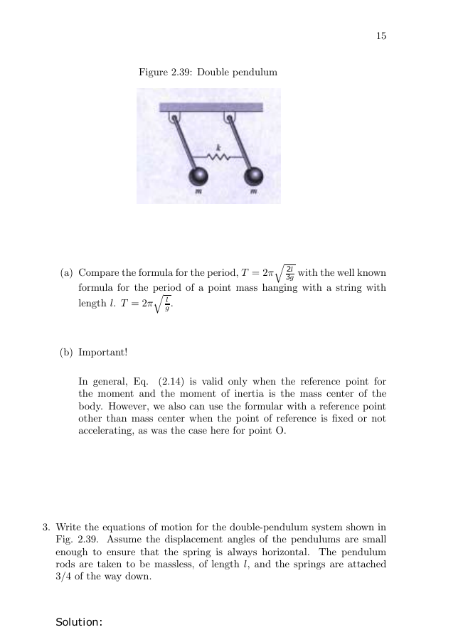
Figure 2.39: Double pendulum
15
3g with the well known
formula for the period of a point mass hanging with a string with
(a) Compare the formula for the period, T = 2πq 2l
length l. T = 2πq l
g .
(b) Important!
In general, Eq.
(2.14) is valid only when the reference point for
the moment and the moment of inertia is the mass center of the
body. However, we also can use the formular with a reference point
other than mass center when the point of reference is xed or not
accelerating, as was the case here for point O.
3. Write the equations of motion for the double-pendulum system shown in
Fig. 2.39. Assume the displacement angles of the pendulums are small
enough to ensure that the spring is always horizontal. The pendulum
rods are taken to be massless, of length l, and the springs are attached
3/4 of the way down.
Solution:
�
16
CHAPTER 2. DYNAMIC MODELS
1G
2G
3
4
l
k
m
m
3
4
l
sin
G
1
3
4
l
sin
G
2
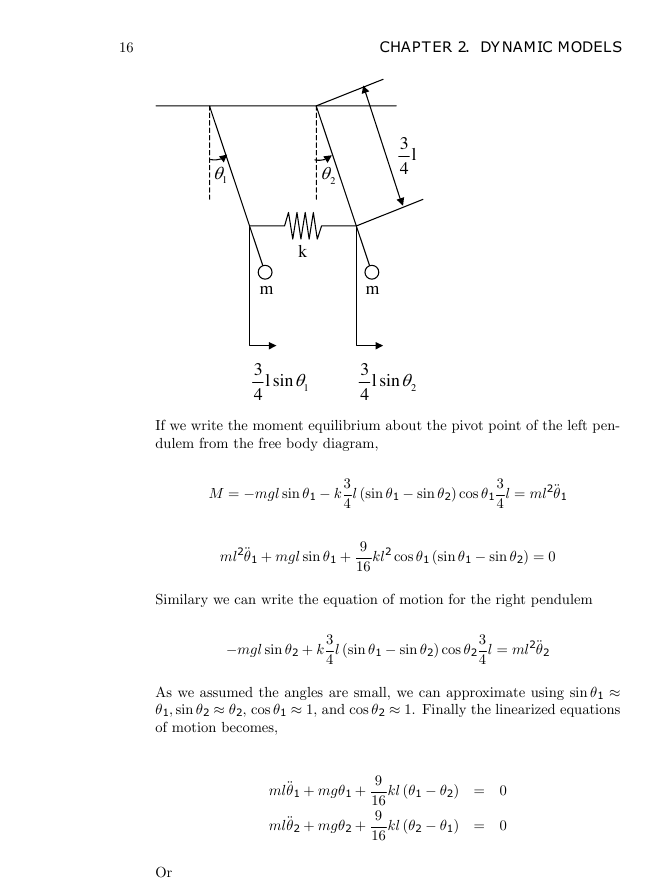
If we write the moment equilibrium about the pivot point of the left pen-
dulem from the free body diagram,
M = −mgl sin θ1 − k
3
4
l (sin θ1 − sin θ2) cos θ1
3
4
l = ml2¤θ1
ml2¤θ1 + mgl sin θ1 +
9
16
kl2 cos θ1 (sin θ1 − sin θ2) = 0
Similary we can write the equation of motion for the right pendulem
−mgl sin θ2 + k
3
4
l (sin θ1 − sin θ2) cos θ2
3
4
l = ml2¤θ2
As we assumed the angles are small, we can approximate using sin θ1 ≈
θ1, sin θ2 ≈ θ2, cos θ1 ≈ 1, and cos θ2 ≈ 1. Finally the linearized equations
of motion becomes,
ml¤θ1 + mgθ1 +
ml¤θ2 + mgθ2 +
9
16
9
16
kl (θ1 − θ2) = 0
kl (θ2 − θ1) = 0
Or
�
17
¤θ1 +
¤θ2 +
g
l
g
l
θ1 +
θ2 +
9
16
9
16
k
m
k
m
(θ1 − θ2) = 0
(θ2 − θ1) = 0
4. Write the equations of motion for a body of mass M suspended from a
xed point by a spring with a constant k. Carefully dene where the
bodys displacement is zero.
Solution:
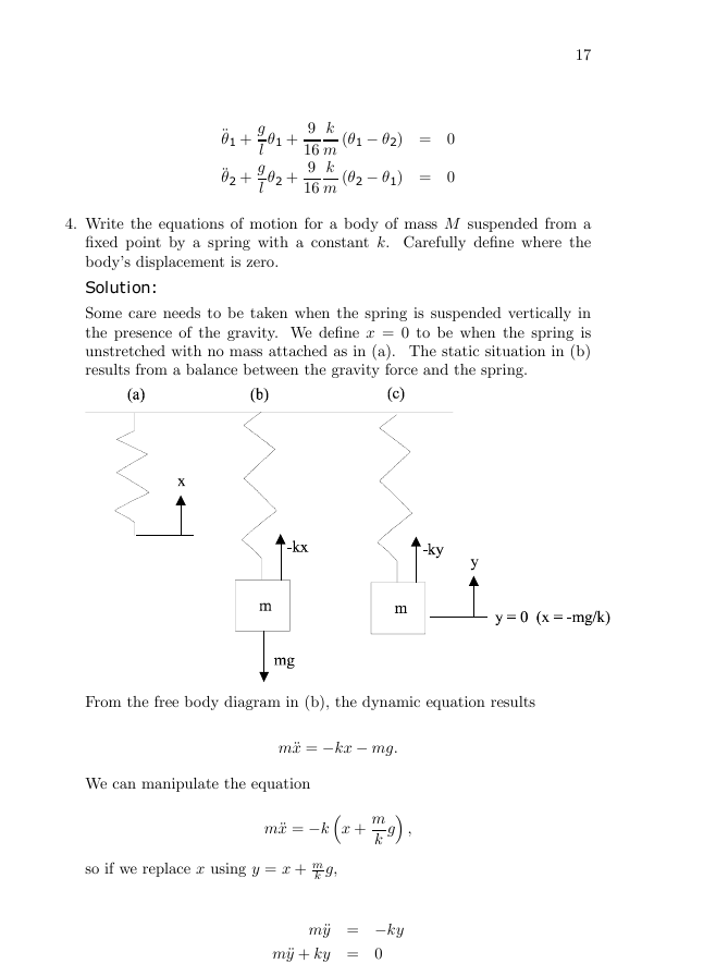
Some care needs to be taken when the spring is suspended vertically in
the presence of the gravity. We dene x = 0 to be when the spring is
unstretched with no mass attached as in (a). The static situation in (b)
results from a balance between the gravity force and the spring.
From the free body diagram in (b), the dynamic equation results
We can manipulate the equation
m¤x = −kx − mg.
m¤x = −k‡x +
m
k
g· ,
so if we replace x using y = x + m
k g,
m¤y = −ky
m¤y + ky = 0
�
18
CHAPTER 2. DYNAMIC MODELS
The equilibrium value of x including the effect of gravity is at x = − m
k g
and y represents the motion of the mass about that equilibrium point.
An alternate solution method, which is applicable for any problem
involving vertical spring motion, is to dene the motion to be with respect
to the static equilibrium point of the springs including the effect of gravity,
and then to proceed as if no gravity was present.
In this problem, we
would dene y to be the motion with respect to the equilibrium point,
then the FBD in (c) would result directly in
5. For the car suspension discussed in Example 2.2,
m¤y = −ky.
(a) write the equations of motion (Eqs. (2.10) and (2.11)) in state-variable
form. Use the state vector x = [ x
œx y
œy ]T .
(b) Plot the position of the car and the wheel after the car hits a unit
bump (i.e., r is a unit step) using MATLAB. Assume that m1 =
10 kg, m2 = 350 kg, kw = 500, 000 N/m, ks = 10, 000 N/m. Find
the value of b that you would prefer if you were a passenger in the
car.
Solution:
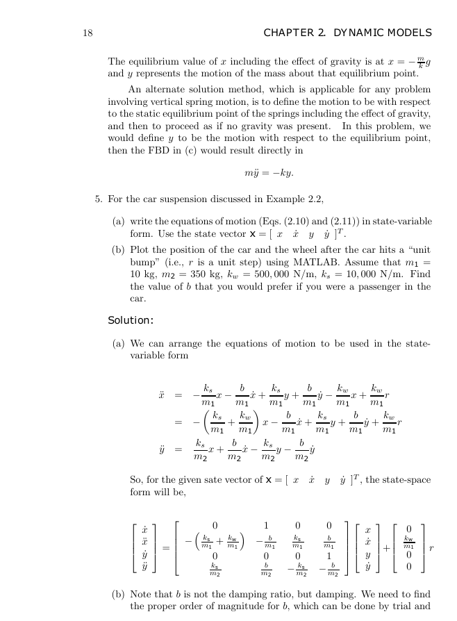
(a) We can arrange the equations of motion to be used in the state-
variable form
¤x = −
ks
m1
x −
= − ks
m1
¤y =
x +
ks
m2
b
m1
kw
œx +
ks
m1
y +
b
m1
+
m1¶ x −
b
m1
b
m2
œx −
ks
m2
y −
œx +
b
m2
œy
œy −
ks
m1
kw
m1
x +
kw
m1
r
y +
b
m1
œy +
kw
m1
r
So, for the given sate vector of x = [ x
form will be,
œx y
œy ]T , the state-space
œx
¤x
œy
¤y
=
−‡ ks
m1
m1· − b
0
+ kw
0
ks
m2
1
0
0
ks
b
m1
m1
m1
0
0
1
m2 − ks
m2 − b
b
m2
x
œx
y
œy
+
0
kw
m1
0
0
r
(b) Note that b is not the damping ratio, but damping. We need to nd
the proper order of magnitude for b, which can be done by trial and
�


 2023年江西萍乡中考道德与法治真题及答案.doc
 2012年重庆南川中考生物真题及答案.doc
 2013年江西师范大学地理学综合及文艺理论基础考研真题.doc
 2020年四川甘孜小升初语文真题及答案I卷.doc
 2020年注册岩土工程师专业基础考试真题及答案.doc
 2023-2024学年福建省厦门市九年级上学期数学月考试题及答案.doc
 2021-2022学年辽宁省沈阳市大东区九年级上学期语文期末试题及答案.doc
 2022-2023学年北京东城区初三第一学期物理期末试卷及答案.doc
 2018上半年江西教师资格初中地理学科知识与教学能力真题及答案.doc
 2012年河北国家公务员申论考试真题及答案-省级.doc
 2020-2021学年江苏省扬州市江都区邵樊片九年级上学期数学第一次质量检测试题及答案.doc
 2022下半年黑龙江教师资格证中学综合素质真题及答案.doc