Solutions
FDTD
Getting Started
Release 8.6
�
�
Contents
1
Table of Contents
Part I
Introduction
Part II Silver Nanowire Tutorial
1 What is FDTD?
2 FDTD Solutions GUI
3 Running Simulations and Optimizations
4 Analyzing simulation data
2
............................................................................................................ 3
............................................................................................................ 4
............................................................................................................ 7
............................................................................................................ 9
12
............................................................................................................ 13
............................................................................................................ 17
26
............................................................................................................ 27
............................................................................................................ 34
44
............................................................................................................ 44
............................................................................................................ 52
1 Discussion and results
2 Modeling instructions
1 Discussion and results
2 Modeling instructions
Part III Ring Resonator Tutorial
Part IV PC Micro Cavity Tutorial
1 Discussion and results
2 Modeling instructions
© 2003 - 2013 Lumerical Solutions, Inc
�
2
1
Getting Started
Introduction
The goal of the Getting Started Guide is to introduce FDTD Solutions and demonstrate how
it can be used to model a number of simple systems.
The FDTD algorithm is useful for design and investigation in a wide variety of applications
involving the propagation of electromagnetic radiation through complicated media. It is
especially useful for describing radiation incident upon or propagating through structures
with strong scattering or diffractive properties. The available alternative computational
methods - often relying on approximate models - frequently provide inaccurate results.
FDTD Solutions is useful for numerous engineering problems of commercial interest
including:
integrated optical components
display technologies
optical storage devices
OLED design
biophotonic sensors
plasmon polariton resonance devices
optical waveguide devices
photonic crystal devices
LCD devices
FDTD Solutions is an accurate and easy to use, versatile design tool capable of treating
this wide variety of applications. This introductory chapter of the Getting Started Guide
introduces the general FDTD method and provides a basic overview of the product usage.
The final sections contain examples that are accompanied by step-by-step instructions so
that you can set up and run the simulations yourself.
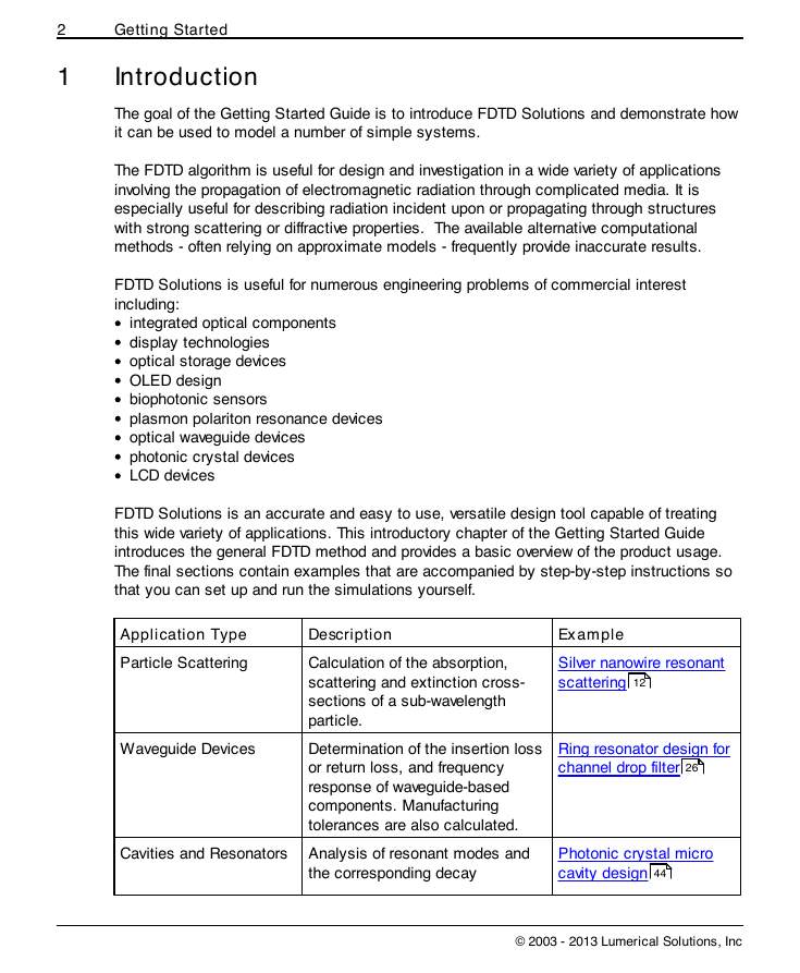
Application Type
Particle Scattering
Waveguide Devices
Cavities and Resonators
Description
Calculation of the absorption,
scattering and extinction cross-
sections of a sub-wavelength
particle.
Determination of the insertion loss
or return loss, and frequency
response of waveguide-based
components. Manufacturing
tolerances are also calculated.
Analysis of resonant modes and
the corresponding decay
Example
Silver nanowire resonant
scattering
12
Ring resonator design for
channel drop filter
26
Photonic crystal micro
cavity design
44
© 2003 - 2013 Lumerical Solutions, Inc
�
Introduction
3
constants for cavities and
resonators.
1.1 What is FDTD?
The Finite Difference Time Domain (FDTD) method has become the state-of-the-art method
for solving Maxwell’s equations in complex geometries. It is a fully vectorial method that
naturally gives both time domain, and frequency domain information to the user, offering
unique insight into all types of problems and appFDTDlications in electromagnetics and
photonics.
The technique is discrete in both space and time. The electromagnetic fields and structural
materials of interest are described on a discrete mesh made up of so-called Yee cells.
Maxwell’s equations are solved discretely in time, where the time step used is related to
the mesh size through the speed of light. This technique is an exact representation of
Maxwell’s equations in the limit that the mesh cell size goes to zero.
Structures to be simulated can have a wide variety of electromagnetic material properties.
Light sources may be added to the simulation. The FDTD method is used to calculate how
the EM fields propagate from the source through the structure. Subsequent iteration results
in the electromagnetic field propagation in time. Typically, the simulation is run until there
are essentially no electromagnetic fields left in the simulation region.
Time domain information can be recorded at any spatial point (or group of points). This data
can be recorded for the duration of the simulation, or it can be recorded as a series of
"snapshots" at times specified by the user.
Frequency domain information at any spatial point (or group of points) may be obtained
through the Fourier transform of the time domain information at that point. Thus, the
© 2003 - 2013 Lumerical Solutions, Inc
�
4
Getting Started
frequency dependence of power flow and modal profiles may be obtained over a wide range
of frequencies from a single simulation.
In addition, results obtained in the near field using the FDTD technique may be transformed
to the far field, in applications where scattering patterns are important.
More information about the FDTD method, including references, can be found in the
Physics of the FDTD Algorithm section of the reference guide.
1.2 FDTD Solutions GUI
This section discusses useful features of the FDTD Solutions Graphical User Interface
(GUI).
In this topic
Graphical User Interface: Windows and
Toolbars
Add Objects to the simulation
Edit Objects
Start a new 2D/3D simulation
4
6
5
7
Graphical User Interface: Windows and Toolbars
The graphical user interface contains useful tools for editing simulations, including
a toolbar for adding objects to the simulation
a toolbar to edit objects
a toolbar to run simulations
an objects tree to show the objects which are currently included in the simulation
a script file editor window
an object library
a window to set up parameter sweeps and optimizations
a results view that shows all the current results for the selected simulation object
a script workspace that shows all the variables in the current scripting environment
a script favorites window that stores the user's favorite script commands
© 2003 - 2013 Lumerical Solutions, Inc
�
Introduction
5
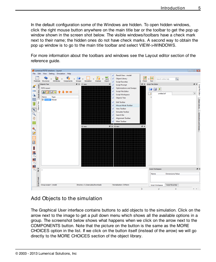
In the default configuration some of the Windows are hidden. To open hidden windows,
click the right mouse button anywhere on the main title bar or the toolbar to get the pop up
window shown in the screen shot below. The visible windows/toolbars have a check mark
next to their name; the hidden ones do not have check marks. A second way to obtain the
pop up window is to go to the main title toolbar and select VIEW->WINDOWS.
For more information about the toolbars and windows see the Layout editor section of the
reference guide.
Add Objects to the simulation
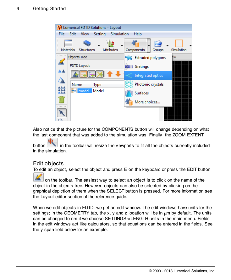
The Graphical User interface contains buttons to add objects to the simulation. Click on the
arrow next to the image to get a pull down menu which shows all the available options in a
group. The screenshot below shows what happens when we click on the arrow next to the
COMPONENTS button. Note that the picture on the button is the same as the MORE
CHOICES option in the list. If we click on the button itself (instead of the arrow) we will go
directly to the MORE CHOICES section of the object library.
© 2003 - 2013 Lumerical Solutions, Inc
�
6
Getting Started
Also notice that the picture for the COMPONENTS button will change depending on what
the last component that was added to the simulation was. Finally, the ZOOM EXTENT
button
in the simulation.
in the toolbar will resize the viewports to fit all the objects currently included
Edit objects
To edit an object, select the object and press E on the keyboard or press the EDIT button
on the toolbar. The easiest way to select an object is to click on the name of the
object in the objects tree. However, objects can also be selected by clicking on the
graphical depiction of them when the SELECT button is pressed. For more information see
the Layout editor section of the reference guide.
When we edit objects in FDTD, we get an edit window. The edit windows have units for the
settings; in the GEOMETRY tab, the x, y and z location will be in m by default. The units
can be changed to nm if we choose SETTINGS->LENGTH units in the main menu. Fields
in the edit windows act like calculators, so that equations can be entered in the fields. See
the y span field below for an example.
© 2003 - 2013 Lumerical Solutions, Inc
�






 2023年江西萍乡中考道德与法治真题及答案.doc
 2012年重庆南川中考生物真题及答案.doc
 2013年江西师范大学地理学综合及文艺理论基础考研真题.doc
 2020年四川甘孜小升初语文真题及答案I卷.doc
 2020年注册岩土工程师专业基础考试真题及答案.doc
 2023-2024学年福建省厦门市九年级上学期数学月考试题及答案.doc
 2021-2022学年辽宁省沈阳市大东区九年级上学期语文期末试题及答案.doc
 2022-2023学年北京东城区初三第一学期物理期末试卷及答案.doc
 2018上半年江西教师资格初中地理学科知识与教学能力真题及答案.doc
 2012年河北国家公务员申论考试真题及答案-省级.doc
 2020-2021学年江苏省扬州市江都区邵樊片九年级上学期数学第一次质量检测试题及答案.doc
 2022下半年黑龙江教师资格证中学综合素质真题及答案.doc