logo资料库

28334 epwm.pdf

第1页 / 共115页
第2页 / 共115页
第3页 / 共115页
第4页 / 共115页
第5页 / 共115页
第6页 / 共115页
第7页 / 共115页
第8页 / 共115页
资料共115页,剩余部分请下载后查看
TMS320x2833x, 2823x Enhanced Pulse Width Modulator (ePWM) Module
Table of Contents
Preface
1 Introduction
1.1 Submodule Overview
1.2 Register Mapping
2 ePWM Submodules
2.1 Overview
2.2 Time-Base (TB) Submodule
2.2.1 Purpose of the Time-Base Submodule
2.2.2 Controlling and Monitoring the Time-base Submodule
2.2.3 Calculating PWM Period and Frequency
2.2.3.1  Time-Base Period Shadow Register
2.2.3.2 Time-Base Clock Synchronization
2.2.3.3  Time-Base Counter Synchronization
2.2.4 Phase Locking the Time-Base Clocks of Multiple ePWM Modules
2.2.5 Time-base Counter Modes and Timing Waveforms
2.3 Counter-Compare (CC) Submodule
2.3.1 Purpose of the Counter-Compare Submodule
2.3.2 Controlling and Monitoring the Counter-Compare Submodule
2.3.3 Operational Highlights for the Counter-Compare Submodule
2.3.4 Count Mode Timing Waveforms
2.4 Action-Qualifier (AQ) Submodule
2.4.1 Purpose of the Action-Qualifier Submodule
2.4.2 Action-Qualifier Submodule Control and Status Register Definitions
2.4.3 Action-Qualifier Event Priority
2.4.4 Waveforms for Common Configurations
2.5 Dead-Band Generator (DB) Submodule
2.5.1 Purpose of the Dead-Band Submodule
2.5.2 Controlling and Monitoring the Dead-Band Submodule
2.5.3 Operational Highlights for the Dead-Band Submodule
2.6 PWM-Chopper (PC) Submodule
2.6.1 Purpose of the PWM-Chopper Submodule
2.6.2 Controlling the PWM-Chopper Submodule
2.6.3 Operational Highlights for the PWM-Chopper Submodule
2.6.4 Waveforms
2.6.4.1  One-Shot Pulse
2.6.4.2  Duty Cycle Control
2.7 Trip-Zone (TZ) Submodule
2.7.1 Purpose of the Trip-Zone Submodule
2.7.2 Controlling and Monitoring the Trip-Zone Submodule
2.7.3 Operational Highlights for the Trip-Zone Submodule
2.7.4 Generating Trip Event Interrupts
2.8 Event-Trigger (ET) Submodule
2.8.1 Operational Overview of the Event-Trigger Submodule
3 Applications to Power Topologies
3.1 Overview of Multiple Modules
3.2 Key Configuration Capabilities
3.3 Controlling Multiple Buck Converters With Independent Frequencies
3.4 Controlling Multiple Buck Converters With Same Frequencies
3.5 Controlling Multiple Half H-Bridge (HHB) Converters
3.6 Controlling Dual 3-Phase Inverters for Motors (ACI and PMSM)
3.7 Practical Applications Using Phase Control Between PWM Modules
3.8 Controlling a 3-Phase Interleaved DC/DC Converter
3.9 Controlling Zero Voltage Switched Full Bridge (ZVSFB) Converter
4 Registers
4.1 Time-Base Submodule Registers
4.2 Counter-Compare Submodule Registers
4.3 Action-Qualifier Submodule Registers
4.4 Dead-Band Submodule Registers
4.5 PWM-Chopper Submodule Control Register
4.6 Trip-Zone Submodule Control and Status Registers
4.7 Event-Trigger Submodule Registers
4.8 Proper Interrupt Initialization Procedure
Appendix A Revision History
TMS320x2833x, 2823x Enhanced Pulse Width Modulator (ePWM) Module Reference Guide Literature Number: SPRUG04A October 2008–Revised July 2009
2 © 2008–2009, Texas Instruments Incorporated SPRUG04A– October 2008– Revised July 2009 Submit Documentation Feedback
2 3 4 1.1 1.2 2.1 2.2 2.3 2.4 2.5 2.6 2.7 2.8 Preface ....................................................................................................................................... 8 Introduction ...................................................................................................................... 11 1 Submodule Overview .................................................................................................. 11 Register Mapping ...................................................................................................... 15 ePWM Submodules ............................................................................................................ 17 Overview ................................................................................................................ 17 Time-Base (TB) Submodule .......................................................................................... 20 Counter-Compare (CC) Submodule ................................................................................. 31 Action-Qualifier (AQ) Submodule .................................................................................... 37 Dead-Band Generator (DB) Submodule ............................................................................ 51 PWM-Chopper (PC) Submodule ..................................................................................... 55 Trip-Zone (TZ) Submodule ........................................................................................... 59 Event-Trigger (ET) Submodule ....................................................................................... 63 Applications to Power Topologies ....................................................................................... 68 Overview of Multiple Modules ........................................................................................ 68 Key Configuration Capabilities ....................................................................................... 68 Controlling Multiple Buck Converters With Independent Frequencies .......................................... 69 Controlling Multiple Buck Converters With Same Frequencies .................................................. 73 Controlling Multiple Half H-Bridge (HHB) Converters ............................................................. 76 Controlling Dual 3-Phase Inverters for Motors (ACI and PMSM) ................................................ 78 Practical Applications Using Phase Control Between PWM Modules .......................................... 82 Controlling a 3-Phase Interleaved DC/DC Converter ............................................................. 83 Controlling Zero Voltage Switched Full Bridge (ZVSFB) Converter ............................................. 87 Registers .......................................................................................................................... 90 Time-Base Submodule Registers .................................................................................... 90 Counter-Compare Submodule Registers ........................................................................... 94 Action-Qualifier Submodule Registers .............................................................................. 97 Dead-Band Submodule Registers .................................................................................. 101 PWM-Chopper Submodule Control Register ..................................................................... 103 Trip-Zone Submodule Control and Status Registers ............................................................ 105 Event-Trigger Submodule Registers ............................................................................... 108 Proper Interrupt Initialization Procedure ........................................................................... 113 Appendix A Revision History ..................................................................................................... 114 3.1 3.2 3.3 3.4 3.5 3.6 3.7 3.8 3.9 4.1 4.2 4.3 4.4 4.5 4.6 4.7 4.8 SPRUG04A– October 2008– Revised July 2009 Submit Documentation Feedback © 2008–2009, Texas Instruments Incorporated Table of Contents 3
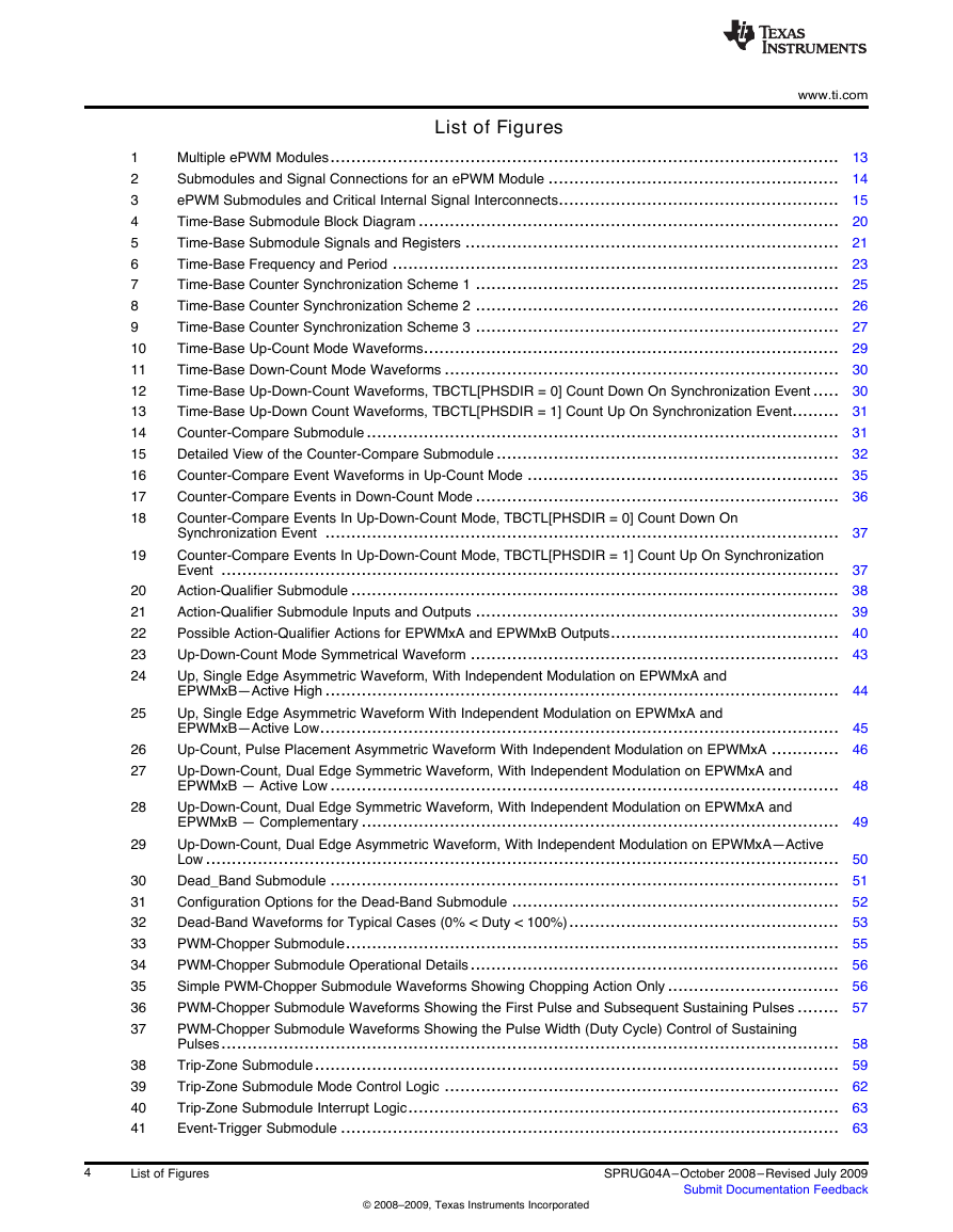
List of Figures www.ti.com Multiple ePWM Modules.................................................................................................. 13 Submodules and Signal Connections for an ePWM Module ........................................................ 14 ePWM Submodules and Critical Internal Signal Interconnects...................................................... 15 Time-Base Submodule Block Diagram ................................................................................. 20 Time-Base Submodule Signals and Registers ........................................................................ 21 Time-Base Frequency and Period ...................................................................................... 23 Time-Base Counter Synchronization Scheme 1 ...................................................................... 25 Time-Base Counter Synchronization Scheme 2 ...................................................................... 26 Time-Base Counter Synchronization Scheme 3 ...................................................................... 27 Time-Base Up-Count Mode Waveforms................................................................................ 29 Time-Base Down-Count Mode Waveforms ............................................................................ 30 Time-Base Up-Down-Count Waveforms, TBCTL[PHSDIR = 0] Count Down On Synchronization Event ..... 30 Time-Base Up-Down Count Waveforms, TBCTL[PHSDIR = 1] Count Up On Synchronization Event......... 31 Counter-Compare Submodule........................................................................................... 31 Detailed View of the Counter-Compare Submodule .................................................................. 32 Counter-Compare Event Waveforms in Up-Count Mode ............................................................ 35 Counter-Compare Events in Down-Count Mode ...................................................................... 36 Counter-Compare Events In Up-Down-Count Mode, TBCTL[PHSDIR = 0] Count Down On Synchronization Event ................................................................................................... 37 Counter-Compare Events In Up-Down-Count Mode, TBCTL[PHSDIR = 1] Count Up On Synchronization Event ....................................................................................................................... 37 Action-Qualifier Submodule .............................................................................................. 38 Action-Qualifier Submodule Inputs and Outputs ...................................................................... 39 Possible Action-Qualifier Actions for EPWMxA and EPWMxB Outputs............................................ 40 Up-Down-Count Mode Symmetrical Waveform ....................................................................... 43 Up, Single Edge Asymmetric Waveform, With Independent Modulation on EPWMxA and EPWMxB—Active High ................................................................................................... 44 Up, Single Edge Asymmetric Waveform With Independent Modulation on EPWMxA and EPWMxB—Active Low.................................................................................................... 45 Up-Count, Pulse Placement Asymmetric Waveform With Independent Modulation on EPWMxA ............. 46 Up-Down-Count, Dual Edge Symmetric Waveform, With Independent Modulation on EPWMxA and EPWMxB — Active Low .................................................................................................. 48 Up-Down-Count, Dual Edge Symmetric Waveform, With Independent Modulation on EPWMxA and EPWMxB — Complementary ............................................................................................ 49 Up-Down-Count, Dual Edge Asymmetric Waveform, With Independent Modulation on EPWMxA—Active Low .......................................................................................................................... 50 Dead_Band Submodule .................................................................................................. 51 Configuration Options for the Dead-Band Submodule ............................................................... 52 Dead-Band Waveforms for Typical Cases (0% < Duty < 100%).................................................... 53 PWM-Chopper Submodule............................................................................................... 55 PWM-Chopper Submodule Operational Details....................................................................... 56 Simple PWM-Chopper Submodule Waveforms Showing Chopping Action Only ................................. 56 PWM-Chopper Submodule Waveforms Showing the First Pulse and Subsequent Sustaining Pulses ........ 57 PWM-Chopper Submodule Waveforms Showing the Pulse Width (Duty Cycle) Control of Sustaining Pulses....................................................................................................................... 58 Trip-Zone Submodule..................................................................................................... 59 Trip-Zone Submodule Mode Control Logic ............................................................................ 62 Trip-Zone Submodule Interrupt Logic................................................................................... 63 Event-Trigger Submodule ................................................................................................ 63 1 2 3 4 5 6 7 8 9 10 11 12 13 14 15 16 17 18 19 20 21 22 23 24 25 26 27 28 29 30 31 32 33 34 35 36 37 38 39 40 41 4 List of Figures © 2008–2009, Texas Instruments Incorporated SPRUG04A– October 2008– Revised July 2009 Submit Documentation Feedback
www.ti.com 42 43 44 45 46 47 48 49 50 51 52 53 54 55 56 57 58 59 60 61 62 63 64 65 66 67 68 69 70 71 72 73 74 75 76 77 78 79 80 81 82 83 84 85 86 87 88 89 90 Event-Trigger Submodule Inter-Connectivity of ADC Start of Conversion......................................... 64 Event-Trigger Submodule Showing Event Inputs and Prescaled Outputs......................................... 65 Event-Trigger Interrupt Generator....................................................................................... 66 Event-Trigger SOCA Pulse Generator.................................................................................. 67 Event-Trigger SOCB Pulse Generator.................................................................................. 67 Simplified ePWM Module................................................................................................. 68 EPWM1 Configured as a Typical Master, EPWM2 Configured as a Slave ....................................... 69 Control of Four Buck Stages. Here FPWM1≠ FPWM2≠ FPWM3≠ FPWM4 .................................................... 70 Buck Waveforms for (Note: Only three bucks shown here).......................................................... 71 Control of Four Buck Stages. (Note: FPWM2 = N x FPWM1).............................................................. 73 Buck Waveforms for (Note: FPWM2 = FPWM1))............................................................................. 74 Control of Two Half-H Bridge Stages (FPWM2 = N x FPWM1) ............................................................ 76 Half-H Bridge Waveforms for (Note: Here FPWM2 = FPWM1 )............................................................ 77 Control of Dual 3-Phase Inverter Stages as Is Commonly Used in Motor Control ............................... 79 3-Phase Inverter Waveforms for (Only One Inverter Shown) ....................................................... 80 Configuring Two PWM Modules for Phase Control ................................................................... 82 Timing Waveforms Associated With Phase Control Between 2 Modules.......................................... 83 Control of a 3-Phase Interleaved DC/DC Converter.................................................................. 84 3-Phase Interleaved DC/DC Converter Waveforms for .............................................................. 85 Controlling a Full-H Bridge Stage (FPWM2 = FPWM1) ..................................................................... 87 ZVS Full-H Bridge Waveforms........................................................................................... 88 Time-Base Period Register (TBPRD)................................................................................... 90 Time-Base Phase Register (TBPHS) ................................................................................... 90 Time-Base Counter Register (TBCTR) ................................................................................. 90 Time-Base Control Register (TBCTL) .................................................................................. 91 Time-Base Status Register (TBSTS) ................................................................................... 93 Counter-Compare A Register (CMPA) ................................................................................. 94 Counter-Compare B Register (CMPB).................................................................................. 94 Counter-Compare Control Register (CMPCTL) ....................................................................... 96 Compare A High Resolution Register (CMPAHR) ................................................................... 97 Action-Qualifier Output A Control Register (AQCTLA) ............................................................... 97 Action-Qualifier Output B Control Register (AQCTLB) ............................................................... 98 Action-Qualifier Software Force Register (AQSFRC)................................................................. 99 Action-Qualifier Continuous Software Force Register (AQCSFRC)............................................... 100 Dead-Band Generator Control Register (DBCTL) ................................................................... 101 Dead-Band Generator Rising Edge Delay Register (DBRED)..................................................... 103 Dead-Band Generator Falling Edge Delay Register (DBFED)..................................................... 103 PWM-Chopper Control Register (PCCTL)............................................................................ 103 Trip-Zone Select Register (TZSEL).................................................................................... 105 Trip-Zone Control Register (TZCTL) .................................................................................. 106 Trip-Zone Enable Interrupt Register (TZEINT)....................................................................... 106 Trip-Zone Flag Register (TZFLG)...................................................................................... 107 Trip-Zone Clear Register (TZCLR) .................................................................................... 107 Trip-Zone Force Register (TZFRC).................................................................................... 108 Event-Trigger Selection Register (ETSEL) ........................................................................... 108 Event-Trigger Prescale Register (ETPS) ............................................................................. 109 Event-Trigger Flag Register (ETFLG)................................................................................. 111 Event-Trigger Clear Register (ETCLR)................................................................................ 112 Event-Trigger Force Register (ETFRC) ............................................................................... 112 SPRUG04A– October 2008– Revised July 2009 Submit Documentation Feedback © 2008–2009, Texas Instruments Incorporated List of Figures 5
List of Tables www.ti.com ePWM Module Control and Status Register Set Grouped by Submodule......................................... 16 Submodule Configuration Parameters.................................................................................. 17 Time-Base Submodule Registers ....................................................................................... 21 Key Time-Base Signals................................................................................................... 22 Counter-Compare Submodule Registers .............................................................................. 32 Counter-Compare Submodule Key Signals............................................................................ 33 Action-Qualifier Submodule Registers.................................................................................. 38 Action-Qualifier Submodule Possible Input Events ................................................................... 39 Action-Qualifier Event Priority for Up-Down-Count Mode ............................................................ 41 Action-Qualifier Event Priority for Up-Count Mode.................................................................... 41 Action-Qualifier Event Priority for Down-Count Mode ................................................................ 41 Behavior if CMPA/CMPB is Greater than the Period ................................................................. 41 Dead-Band Generator Submodule Registers.......................................................................... 51 Classical Dead-Band Operating Modes ............................................................................... 53 Dead-Band Delay Values in μS as a Function of DBFED and DBRED ........................................... 54 PWM-Chopper Submodule Registers .................................................................................. 55 Possible Pulse Width Values for SYSCLKOUT = 100 MHz ......................................................... 57 Trip-Zone Submodule Registers......................................................................................... 60 Possible Actions On a Trip Event ....................................................................................... 61 Event-Trigger Submodule Registers ................................................................................... 65 Time-Base Period Register (TBPRD) Field Descriptions ............................................................ 90 Time-Base Phase Register (TBPHS) Field Descriptions............................................................. 90 Time-Base Counter Register (TBCTR) Field Descriptions........................................................... 90 Time-Base Control Register (TBCTL) Field Descriptions ............................................................ 91 Time-Base Status Register (TBSTS) Field Descriptions ............................................................. 93 Counter-Compare A Register (CMPA) Field Descriptions ........................................................... 94 Counter-Compare B Register (CMPB) Field Descriptions ........................................................... 95 Counter-Compare Control Register (CMPCTL) Field Descriptions ................................................ 96 Compare A High Resolution Register (CMPAHR) Field Descriptions.............................................. 97 Action-Qualifier Output A Control Register (AQCTLA) Field Descriptions ........................................ 97 Action-Qualifier Output B Control Register (AQCTLB) Field Descriptions ........................................ 98 Action-Qualifier Software Force Register (AQSFRC) Field Descriptions .......................................... 99 Action-qualifier Continuous Software Force Register (AQCSFRC) Field Descriptions ......................... 100 Dead-Band Generator Control Register (DBCTL) Field Descriptions............................................. 102 Dead-Band Generator Rising Edge Delay Register (DBRED) Field Descriptions............................... 103 Dead-Band Generator Falling Edge Delay Register (DBFED) Field Descriptions .............................. 103 PWM-Chopper Control Register (PCCTL) Bit Descriptions ....................................................... 104 Trip-Zone Submodule Select Register (TZSEL) Field Descriptions .............................................. 105 Trip-Zone Control Register (TZCTL) Field Descriptions ............................................................ 106 Trip-Zone Enable Interrupt Register (TZEINT) Field Descriptions ................................................ 106 Trip-Zone Flag Register (TZFLG) Field Descriptions ............................................................... 107 Trip-Zone Clear Register (TZCLR) Field Descriptions ............................................................. 108 Trip-Zone Force Register (TZFRC) Field Descriptions ............................................................. 108 Event-Trigger Selection Register (ETSEL) Field Descriptions .................................................... 109 Event-Trigger Prescale Register (ETPS) Field Descriptions ...................................................... 110 Event-Trigger Flag Register (ETFLG) Field Descriptions........................................................... 111 Event-Trigger Clear Register (ETCLR) Field Descriptions ......................................................... 112 1 2 3 4 5 6 7 8 9 10 11 12 13 14 15 16 17 18 19 20 21 22 23 24 25 26 27 28 29 30 31 32 33 34 35 36 37 38 39 40 41 42 43 44 45 46 47 6 List of Tables © 2008–2009, Texas Instruments Incorporated SPRUG04A– October 2008– Revised July 2009 Submit Documentation Feedback
www.ti.com 48 49 Event-Trigger Force Register (ETFRC) Field Descriptions ........................................................ 112 Changes for this Revision............................................................................................... 114 SPRUG04A– October 2008– Revised July 2009 Submit Documentation Feedback © 2008–2009, Texas Instruments Incorporated List of Tables 7
Preface SPRUG04A–October 2008–Revised July 2009 Read This First The Enhanced Pulse Width Modulator (ePWM) module described in this reference guide is a Type 0 ePWM. See the TMS320x28xx, 28xxx DSP Peripheral Reference Guide (SPRU566) for a list of all devices with a ePWM module of the same type, to determine the differences between the types, and for a list of device-specific differences within a type. This reference guide includes an overview of the module and information about each of its sub-modules: • Time-Base Module • Counter Compare Module • Action Qualifier Module • Dead-Band Generator Module • PWM Chopper (PC) Module • Trip Zone Module • Event Trigger Module Related Documentation From Texas Instruments The following books describe the TMS320F2833x, 2823x module and related support tools that are available on the TI website: Data Manual and Errata— SPRS439 — TMS320F28335, TMS320F28334, TMS320F28332, TMS320F28235, TMS320F28234, TMS320F28232 Digital Signal Controllers (DSCs) Data Manual contains the pinout, signal descriptions, as well as electrical and timing specifications for the F2833x/2823x devices. SPRZ272 — TMS320F28335, TMS320F28334, TMS320F28332, TMS320F28235, TMS320F28234, TMS320F28232 DSC Silicon Errata describes the advisories and usage notes for different versions of silicon. CPU User's Guides— SPRU430 — TMS320C28x CPU and Instruction Set Reference Guide describes the central processing unit (CPU) and the assembly language instructions of the TMS320C28x fixed-point digital signal processors (DSPs). It also describes emulation features available on these DSPs. SPRUEO2 — TMS320C28x Floating Point Unit and Instruction Set Reference Guide describes the floating-point unit and includes the instructions for the FPU. Peripheral Guides— SPRU566 — TMS320x28xx, 28xxx DSP Peripheral Reference Guide describes the peripheral reference guides of the 28x digital signal processors (DSPs). SPRUFB0 — TMS320x2833x, 2823x System Control and Interrupts Reference Guide describes the various interrupts and system control features of the 2833x and 2823x digital signal controllers (DSCs). SPRU812 — TMS320x2833x, 2823x Analog-to-Digital Converter (ADC) Reference Guide describes how to configure and use the on-chip ADC module, which is a 12-bit pipelined ADC. SPRU949 — TMS320x2833x, 2823x DSC External Interface (XINTF) Reference Guide describes the XINTF, which is a nonmultiplexed asynchronous bus, as it is used on the 2833x and 2823x devices. 8 Preface © 2008–2009, Texas Instruments Incorporated SPRUG04A– October 2008– Revised July 2009 Submit Documentation Feedback
分享到:
收藏