Universal Serial Bus 3.0 Specification
Revision History
Acknowledgement of USB 3.0 Technical Contribution
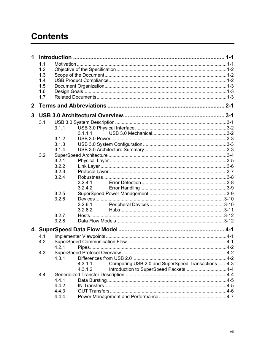
Contents
1 Introduction
1.1 Motivation
1.2 Objective of the Specification
1.3 Scope of the Document
1.4 USB Product Compliance
1.5 Document Organization
1.6 Design Goals
1.7 Related Documents
2 Terms and Abbreviations
3 USB 3.0 Architectural Overview
3.1 USB 3.0 System Description
3.1.1 USB 3.0 Physical Interface
3.1.1.1 USB 3.0 Mechanical
3.1.2 USB 3.0 Power
3.1.3 USB 3.0 System Configuration
3.1.4 USB 3.0 Architecture Summary
3.2 SuperSpeed Architecture
3.2.1 Physical Layer
3.2.2 Link Layer
3.2.3 Protocol Layer
3.2.4 Robustness
3.2.4.1 Error Detection
3.2.4.2 Error Handling
3.2.5 SuperSpeed Power Management
3.2.6 Devices
3.2.6.1 Peripheral Devices
3.2.6.2 Hubs
3.2.7 Hosts
3.2.8 Data Flow Models
4. SuperSpeed Data Flow Model
4.1 Implementer Viewpoints
4.2 SuperSpeed Communication Flow
4.2.1 Pipes
4.3 SuperSpeed Protocol Overview
4.3.1 Differences from USB 2.0
4.3.1.1 Comparing USB 2.0 and SuperSpeed Transactions
4.3.1.2 Introduction to SuperSpeed Packets
4.4 Generalized Transfer Description
4.4.1 Data Bursting
4.4.2 IN Transfers
4.4.3 OUT Transfers
4.4.4 Power Management and Performance
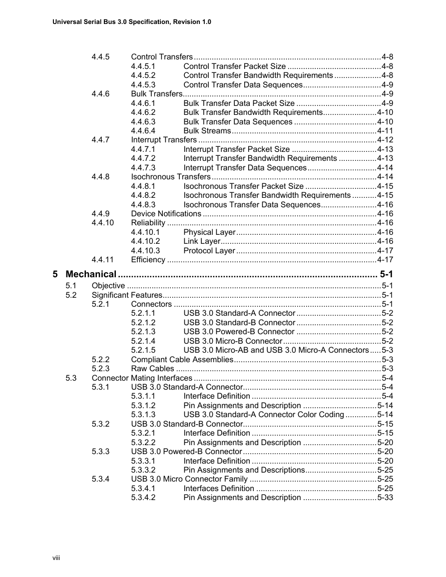
4.4.5 Control Transfers
4.4.5.1 Control Transfer Packet Size
4.4.5.2 Control Transfer Bandwidth Requirements
4.4.5.3 Control Transfer Data Sequences
4.4.6 Bulk Transfers
4.4.6.1 Bulk Transfer Data Packet Size
4.4.6.2 Bulk Transfer Bandwidth Requirements
4.4.6.3 Bulk Transfer Data Sequences
4.4.6.4 Bulk Streams
4.4.7 Interrupt Transfers
4.4.7.1 Interrupt Transfer Packet Size
4.4.7.2 Interrupt Transfer Bandwidth Requirements
4.4.7.3 Interrupt Transfer Data Sequences
4.4.8 Isochronous Transfers
4.4.8.1 Isochronous Transfer Packet Size
4.4.8.2 Isochronous Transfer Bandwidth Requirements
4.4.8.3 Isochronous Transfer Data Sequences
4.4.9 Device Notifications
4.4.10 Reliability
4.4.10.1 Physical Layer
4.4.10.2 Link Layer
4.4.10.3 Protocol Layer
4.4.11 Efficiency
5 Mechanical
5.1 Objective
5.2 Significant Features
5.2.1 Connectors
5.2.1.1 USB 3.0 Standard-A Connector
5.2.1.2 USB 3.0 Standard-B Connector
5.2.1.3 USB 3.0 Powered-B Connector
5.2.1.4 USB 3.0 Micro-B Connector
5.2.1.5 USB 3.0 Micro-AB and USB 3.0 Micro-A Connectors
5.2.2 Compliant Cable Assemblies
5.2.3 Raw Cables
5.3 Connector Mating Interfaces
5.3.1 USB 3.0 Standard-A Connector
5.3.1.1 Interface Definition
5.3.1.2 Pin Assignments and Description
5.3.1.3 USB 3.0 Standard-A Connector Color Coding
5.3.2 USB 3.0 Standard-B Connector
5.3.2.1 Interface Definition
5.3.2.2 Pin Assignments and Description
5.3.3 USB 3.0 Powered-B Connector
5.3.3.1 Interface Definition
5.3.3.2 Pin Assignments and Descriptions
5.3.4 USB 3.0 Micro Connector Family
5.3.4.1 Interfaces Definition
5.3.4.2 Pin Assignments and Description
5.4 Cable Construction and Wire Assignments
5.4.1 Cable Construction
5.4.2 Wire Assignments
5.4.3 Wire Gauges and Cable Diameters
5.5 Cable Assemblies
5.5.1 USB 3.0 Standard-A to USB 3.0 Standard-B Cable Assembly
5.5.2 USB 3.0 Standard-A to USB 3.0 Standard-A Cable Assembly
5.5.3 USB 3.0 Standard-A to USB 3.0 Micro-B Cable Assembly
5.5.4 USB 3.0 Micro-A to USB 3.0 Micro-B Cable Assembly
5.5.5 USB 3.0 Micro-A to USB 3.0 Standard-B Cable Assembly
5.5.6 USB 3.0 Icon Location
5.5.7 Cable Assembly Length
5.6 Electrical Requirements
5.6.1 SuperSpeed Electrical Requirements
5.6.1.1 Raw Cable
5.6.1.1.1 Characteristic Impedance
5.6.1.1.2 Intra-Pair Skew
5.6.1.1.3 Differential Insertion Loss
5.6.1.2 Mated Connector
5.6.1.3 Mated Cable Assemblies
5.6.1.3.1 Differential Insertion Loss (EIA-360-101)
5.6.1.3.2 Differential Near-End Crosstalk Between SuperSpeed Pairs (EIA-360-90)
5.6.1.3.3 Differential Crosstalk Between D+/D- and SuperSpeed Pairs (EIA-360-90)
5.6.1.3.4 Differential-to-Common-Mode Conversion
5.6.2 DC Electrical Requirements
5.6.2.1 Low Level Contact Resistance (EIA 364-23B)
5.6.2.2 Dielectric Strength (EIA 364-20)
5.6.2.3 Insulation Resistance (EIA 364-21)
5.6.2.4 Contact Current Rating (EIA 364-70, Method 2)
5.7 Mechanical and Environmental Requirements
5.7.1 Mechanical Requirements
5.7.1.1 Insertion Force (EIA 364-13)
5.7.1.2 Extraction Force (EIA 364-13)
5.7.1.3 Durability or Insertion/Extraction Cycles (EIA 364-09)
5.7.1.4 Cable Flexing (EIA 364-41, Condition I)
5.7.1.5 Cable Pull-Out (EIA 364-38, Condition A)
5.7.1.6 Peel Strength (USB 3.0 Micro Connector Family Only)
5.7.1.7 4-Axes Continuity Test (USB 3.0 Micro Connector Family Only)
5.7.1.8 Wrenching Strength (Reference, USB 3.0 Micro Connector Family Only)
5.7.1.9 Lead Co-Planarity
5.7.1.10 Solderability
5.7.1.11 Restriction of Hazardous Substances (RoHS) Compliance
5.7.2 Environmental Requirements
5.7.3 Materials
5.8 Implementation Notes and Design Guides
5.8.1 Mated Connector Dimensions
5.8.2 EMI Management
5.8.3 Stacked Connectors
6 Physical Layer
6.1 Physical Layer Overview
6.2 Physical Layer Functions
6.2.1 Measurement Overview
6.2.2 Channel Overview
6.3 Symbol Encoding
6.3.1 Serialization and Deserialization of Data
6.3.2 Normative 8b/10b Decode Rules
6.3.3 Data Scrambling
6.3.4 8b/10b Decode Errors
6.3.5 Special Symbols for Framing and Link Management
6.4 Link Initialization and Training
6.4.1 Normative Training Sequence Rules
6.4.1.1 Training Control Bits
6.4.1.2 Training Sequence Values
6.4.2 Lane Polarity Inversion
6.4.3 Elasticity Buffer and SKP Ordered Set
6.4.4 Compliance Pattern
6.5 Clock and Jitter
6.5.1 Informative Jitter Budgeting
6.5.2 Normative Clock Recovery Function
6.5.3 Normative Spread Spectrum Clocking (SSC)
6.5.4 Normative Slew Rate Limit
6.6 Signaling
6.6.1 Eye Diagrams
6.6.2 Voltage Level Definitions
6.6.3 Tx and Rx Input Parasitics
6.7 Transmitter Specifications
6.7.1 Transmitter Electrical Parameters
6.7.2 Low Power Transmitter
6.7.3 Transmitter Eye
6.7.4 Tx Compliance Reference Receiver Equalize Function
6.7.5 Informative Transmitter De-emphasis
6.7.6 Entry into Electrical Idle, U1
6.8 Receiver Specifications
6.8.1 Receiver Equalization Training
6.8.2 Informative Receiver CTLE Function
6.8.3 Receiver Electrical Parameters
6.8.4 Receiver Loopback
6.8.4.1 Loopback BERT
6.8.5 Normative Receiver Tolerance Compliance Test
6.9 Low Frequency Periodic Signaling (LFPS)
6.9.1 LFPS Signal Definition
6.9.2 Example LFPS Handshake for U1/U2 Exit, Loopback Exit, and U3 Wakeup
6.9.3 Warm Reset
6.10 Transmitter and Receiver DC Specifications
6.10.1 Informative ESD Protection
6.10.2 Informative Short Circuit Requirements
6.10.3 Normative High Impedance Reflections
6.11 Receiver Detection
6.11.1 Rx Detect Overview
6.11.2 Rx Detect Sequence
6.11.3 Upper Limit on Channel Capacitance
7 Link Layer
7.1 Byte Ordering
7.2 Link Management and Flow Control
7.2.1 Packets and Packet Framing
7.2.1.1 Header Packet Structure
7.2.1.1.1 Header Packet Framing
7.2.1.1.2 Packet Header
7.2.1.1.3 Link Control Word
7.2.1.2 Data Packet Payload Structure
7.2.1.2.1 Data Packet Payload Framing
7.2.1.2.2 Data Packet Payload
7.2.1.2.3 Spacing Between Data Packet Header and Data Packet Payload
7.2.2 Link Commands
7.2.2.1 Link Command Structure
7.2.2.2 Link Command Word Definition
7.2.2.3 Link Command Placement
7.2.3 Logical Idle
7.2.4 Link Command Usage for Flow Control, Error Recovery, and Power Management
7.2.4.1 Header Packet Flow Control and Error Recovery
7.2.4.1.1 Initialization
7.2.4.1.2 General Rules of LGOOD_n and LCRD_x Usage
7.2.4.1.3 Transmitting Header Packets
7.2.4.1.4 Receiving Header Packets
7.2.4.1.5 Rx Header Buffer Credit
7.2.4.1.6 Receiving Data Packet Payload
7.2.4.1.7 Receiving LGOOD_n
7.2.4.1.8 Receiving LCRD_x
7.2.4.1.9 Receiving LBAD
7.2.4.1.10 Transmitter Timers
7.2.4.2 Link Power Management and Flow
7.2.4.2.1 Power Management Link Timers
7.2.4.2.2 Low Power Link State Initiation
7.2.4.2.3 U1/U2 Entry Flow
7.2.4.2.4 U3 Entry Flow
7.2.4.2.5 Concurrent Low Power Link Management Flow
7.2.4.2.6 Concurrent Low Power Link Management and Recovery Flow
7.2.4.2.7 Low Power Link State Exit Flow
7.3 Link Error Rules/Recovery
7.3.1 Overview of SuperSpeed Bit Errors
7.3.2 Link Error Types, Detection, and Recovery
7.3.3 Header Packet Errors
7.3.3.1 Packet Framing Error
7.3.3.2 Header Packet Error
7.3.3.3 Rx Header Sequence Number Error
7.3.4 Link Command Errors
7.3.5 ACK Tx Header Sequence Number Error
7.3.6 Header Sequence Number Advertisement Error
7.3.7 Rx Header Buffer Credit Advertisement Error
7.3.8 Training Sequence Error
7.3.9 8b/10b Errors
7.3.10 Summary of Error Types and Recovery
7.4 PowerOn Reset and Inband Reset
7.4.1 PowerOn Reset
7.4.2 Inband Reset
7.5 Link Training and Status State Machine (LTSSM)
7.5.1 SS.Disabled
7.5.1.1 SS.Disabled Requirements
7.5.1.2 Exit from SS.Disabled
7.5.2 SS.Inactive
7.5.2.1 SS.Inactive Substate Machines
7.5.2.2 SS.Inactive Requirements
7.5.2.3 SS.Inactive.Quiet
7.5.2.3.1 SS.Inactive.Quiet Requirements
7.5.2.3.2 Exit from SS.Inactive.Quiet
7.5.2.4 SS.Inactive.Disconnect.Detect
7.5.2.4.1 SS.Inactive.Disconnect.Detect Requirements
7.5.2.4.2 Exit from SS.Inactive.Disconnect.Detect
7.5.3 Rx.Detect
7.5.3.1 Rx.Detect Substate Machines
7.5.3.2 Rx.Detect Requirements
7.5.3.3 Rx.Detect.Reset
7.5.3.3.1 Rx.Detect.Reset Requirements
7.5.3.3.2 Exit from Rx.Detect.Reset
7.5.3.4 Rx.Detect.Active
7.5.3.5 Rx.Detect.Active Requirements
7.5.3.6 Exit from Rx.Detect.Active
7.5.3.7 Rx.Detect.Quiet
7.5.3.7.1 Rx.Detect.Quiet Requirements
7.5.3.7.2 Exit from Rx.Detect.Quiet
7.5.4 Polling
7.5.4.1 Polling Substate Machines
7.5.4.2 Polling Requirements
7.5.4.3 Polling.LFPS
7.5.4.3.1 Polling.LFPS Requirements
7.5.4.3.2 Exit from Polling.LFPS
7.5.4.4 Polling.RxEQ
7.5.4.4.1 Polling.RxEQ Requirements
7.5.4.4.2 Exit from Polling.RxEQ
7.5.4.5 Polling.Active
7.5.4.5.1 Polling.Active Requirements
7.5.4.5.2 Exit from Polling.Active
7.5.4.6 Polling.Configuration
7.5.4.6.1 Polling.Configuration Requirements
7.5.4.6.2 Exit from Polling.Configuration
7.5.4.7 Polling.Idle
7.5.4.7.1 Polling.Idle Requirements
7.5.4.7.2 Exit from Polling.Idle
7.5.5 Compliance Mode
7.5.5.1 Compliance Mode Requirements
7.5.5.2 Exit from Compliance Mode
7.5.6 U0
7.5.6.1 U0 Requirements
7.5.6.2 Exit from U0
7.5.7 U1
7.5.7.1 U1 Requirements
7.5.7.2 Exit from U1
7.5.8 U2
7.5.8.1 U2 Requirements
7.5.8.2 Exit from U2
7.5.9 U3
7.5.9.1 U3 Requirements
7.5.9.2 Exit from U3
7.5.10 Recovery
7.5.10.1 Recovery Substate Machines
7.5.10.2 Recovery Requirements
7.5.10.3 Recovery.Active
7.5.10.3.1 Recovery.Active Requirements
7.5.10.3.2 Exit from Recovery.Active
7.5.10.4 Recovery.Configuration
7.5.10.4.1 Recovery.Configuration Requirements
7.5.10.4.2 Exit from Recovery.Configuration
7.5.10.5 Recovery.Idle
7.5.10.5.1 Recovery.Idle Requirements
7.5.10.5.2 Exit from Recovery.Idle
7.5.11 Loopback
7.5.11.1 Loopback Substate Machines
7.5.11.2 Loopback Requirements
7.5.11.3 Loopback.Active
7.5.11.3.1 Loopback.Active Requirements
7.5.11.3.2 Exit from Loopback.Active
7.5.11.4 Loopback.Exit
7.5.11.4.1 Loopback.Exit Requirements
7.5.11.4.2 Exit from Loopback.Exit
7.5.12 Hot Reset
7.5.12.1 Hot Reset Substate Machines
7.5.12.2 Hot Reset Requirements
7.5.12.3 Hot Reset.Active
7.5.12.3.1 Hot Reset.Active Requirements
7.5.12.3.2 Exit from Hot Reset.Active
7.5.12.4 Hot Reset.Exit
7.5.12.4.1 Hot Reset.Exit Requirements
7.5.12.4.2 Exit from Hot Reset.Exit
8 Protocol Layer
8.1 SuperSpeed Transactions
8.2 Packet Types
8.3 Packet Formats
8.3.1 Fields Common to all Headers
8.3.1.1 Reserved Values and Reserved Field Handling
8.3.1.2 Type Field
8.3.1.3 CRC-16
8.3.1.4 Link Control Word
8.4 Link Management Packet (LMP)
8.4.1 Subtype Field
8.4.2 Set Link Function
8.4.3 U2 Inactivity Timeout
8.4.4 Vendor Device Test
8.4.5 Port Capabilities
8.4.6 Port Configuration
8.4.7 Port Configuration Response
8.5 Transaction Packet (TP)
8.5.1 Acknowledgement (ACK) Transaction Packet
8.5.2 Not Ready (NRDY) Transaction Packet
8.5.3 Endpoint Ready (ERDY) Transaction Packet
8.5.4 STATUS Transaction Packet
8.5.5 STALL Transaction Packet
8.5.6 Device Notification (DEV_NOTIFICATION) Transaction Packet
8.5.6.1 Function Wake Device Notification
8.5.6.2 Latency Tolerance Message (LTM) Device Notification
8.5.6.3 Bus Interval Adjustment Message Device Notification
8.5.6.4 Function Wake Notification
8.5.6.5 Latency Tolerance Messaging
8.5.6.5.1 Optional Normative LTM and BELT Requirements
8.5.6.6 Bus Interval Adjustment Message
8.5.7 PING Transaction Packet
8.5.8 PING_RESPONSE Transaction Packet
8.6 Data Packet (DP)
8.7 Isochronous Timestamp Packet (ITP)
8.8 Addressing Triple
8.9 Route String Field
8.9.1 Route String Port Field
8.9.2 Route String Port Field Width
8.9.3 Port Number
8.10 Transaction Packet Usages
8.10.1 Flow Control Conditions
8.10.2 Burst Transactions
8.10.3 Short Packets
8.11 TP or DP Responses
8.11.1 Device Response to TP Requesting Data
8.11.2 Host Response to Data Received from a Device
8.11.3 Device Response to Data Received from the Host
8.11.4 Device Response to a SETUP DP
8.12 TP Sequences
8.12.1 Bulk Transactions
8.12.1.1 State Machine Notation Information
8.12.1.2 Bulk IN Transactions
8.12.1.3 Bulk OUT Transactions
8.12.1.4 Bulk Streaming Protocol
8.12.1.4.1 Stream IDs
8.12.1.4.2 Bulk IN Stream Protocol
8.12.1.4.3 Bulk OUT Stream Protocol
8.12.2 Control Transfers
8.12.2.1 Reporting Status Results
8.12.2.2 Variable-length Data Stage
8.12.2.3 STALL TPs Returned by Control Pipes
8.12.3 Bus Interval and Service Interval
8.12.4 Interrupt Transactions
8.12.4.1 Interrupt IN Transactions
8.12.4.2 Interrupt OUT Transactions
8.12.5 Host Timing Information
8.12.6 Isochronous Transactions
8.12.6.1 Host Flexibility in Performing Isochronous Transactions
8.12.6.2 Device Response to Isochronous IN Transactions
8.12.6.3 Host Processing of Isochronous IN Transactions
8.12.6.4 Device Response to an Isochronous OUT Data Packet
8.13 Timing Parameters
9 Device Framework
9.1 USB Device States
9.1.1 Visible Device States
9.1.1.1 Attached
9.1.1.2 Powered
9.1.1.3 Default
9.1.1.4 Address
9.1.1.5 Configured
9.1.1.6 Suspended
9.1.2 Bus Enumeration
9.2 Generic Device Operations
9.2.1 Dynamic Attachment and Removal
9.2.2 Address Assignment
9.2.3 Configuration
9.2.4 Data Transfer
9.2.5 Power Management
9.2.5.1 Power Budgeting
9.2.5.2 Changing Device Suspend State
9.2.5.3 Function Suspend
9.2.5.4 Changing Function Suspend State
9.2.6 Request Processing
9.2.6.1 Request Processing Timing
9.2.6.2 Reset/Resume Recovery Time
9.2.6.3 Set Address Processing
9.2.6.4 Standard Device Requests
9.2.6.5 Class-specific Requests
9.2.6.6 Speed Dependent Descriptors
9.2.7 Request Error
9.3 USB Device Requests
9.3.1 bmRequestType
9.3.2 bRequest
9.3.3 wValue
9.3.4 wIndex
9.3.5 wLength
9.4 Standard Device Requests
9.4.1 Clear Feature
9.4.2 Get Configuration
9.4.3 Get Descriptor
9.4.4 Get Interface
9.4.5 Get Status
9.4.6 Set Address
9.4.7 Set Configuration
9.4.8 Set Descriptor
9.4.9 Set Feature
9.4.10 Set Interface
9.4.11 Set Isochronous Delay
9.4.12 Set SEL
9.4.13 Synch Frame
9.5 Descriptors
9.6 Standard USB Descriptor Definitions
9.6.1 Device
9.6.2 Binary Device Object Store (BOS)
9.6.2.1 USB 2.0 Extension
9.6.2.2 SuperSpeed USB Device Capability
9.6.2.3 Container ID
9.6.3 Configuration
9.6.4 Interface Association
9.6.5 Interface
9.6.6 Endpoint
9.6.7 SuperSpeed Endpoint Companion
9.6.8 String
9.7 Device Class Definitions
9.7.1 Descriptors
9.7.2 Interface(s)
9.7.3 Requests
10 Hub, Host Downstream Port, and Device Upstream Port Specification
10.1 Hub Feature Summary
10.1.1 SuperSpeed Capable Host with SuperSpeed Capable Software
10.1.2 USB 2.0 Host
10.1.3 Hub Connectivity
10.1.3.1 Packet Signaling Connectivity
10.1.3.2 Routing Information
10.1.4 Resume Connectivity
10.1.5 Hub Fault Recovery Mechanisms
10.1.6 Hub Header Packet Buffer Architecture
10.1.6.1 Hub Data Buffer Architecture
10.2 Hub Power Management
10.2.1 Link States
10.2.2 Hub Downstream Port U1/U2 Timers
10.2.3 Downstream/Upstream Port Link State Transitions
10.3 Hub Downstream Facing Ports
10.3.1 Hub Downstream Facing Port State Descriptions
10.3.1.1 DSPORT.Powered-off
10.3.1.2 DSPORT.Disconnected (Waiting for SS Connect)
10.3.1.3 DSPORT.Training
10.3.1.4 DSPORT.ERROR
10.3.1.5 DSPORT.Enabled
10.3.1.6 DSPORT.Resetting
10.3.1.7 DSPORT.Compliance
10.3.1.8 DSPORT.Loopback
10.3.1.9 DSPORT.Disabled
10.3.2 Disconnect Detect Mechanism
10.3.3 Labeling
10.4 Hub Downstream Facing Port Power Management
10.4.1 Downstream Facing Port PM Timers
10.4.2 Hub Downstream Facing Port State Descriptions
10.4.2.1 Enabled U0 States
10.4.2.2 Attempt U0 – U1 Transition
10.4.2.3 Attempt U0 – U2 Transition
10.4.2.4 Link in U1
10.4.2.5 Link in U2
10.4.2.6 Link in U3
10.5 Hub Upstream Facing Port
10.5.1 Upstream Facing Port State Descriptions
10.5.1.1 USPORT.Powered-off
10.5.1.2 USPORT.Powered-on
10.5.1.3 USPORT.Training
10.5.1.4 USPORT.Connected
10.5.1.5 USPORT.Error
10.5.1.6 USPORT.Enabled
10.5.2 Hub Connect State Machine
10.5.2.1 Hub Connect State Descriptions
10.5.2.2 HCONNECT.Powered-off
10.5.2.3 HCONNECT.Attempt SS Connect
10.5.2.4 HCONNECT.Connected on SS
10.6 Upstream Facing Port Power Management
10.6.1 Upstream Facing Port PM Timer
10.6.2 Hub Upstream Facing Port State Descriptions
10.6.2.1 Enabled U0 States
10.6.2.2 Attempt U0 – U1 Transition
10.6.2.3 Attempt U0 – U2 Transition
10.6.2.4 Link in U1
10.6.2.5 Link in U2
10.6.2.6 Link in U3
10.7 Hub Header Packet Forwarding and Data Repeater
10.7.1 Hub Elasticity Buffer
10.7.2 SKP Ordered Sets
10.7.3 Interpacket Spacing
10.7.4 Header Packet Buffer Architecture
10.7.5 Upstream Facing Port Tx
10.7.6 Upstream Facing Port Tx State Descriptions
10.7.6.1 Tx IDLE
10.7.6.2 Tx Header
10.7.6.3 Tx Data
10.7.6.4 Tx Data Abort
10.7.6.5 Tx Link Command
10.7.7 Upstream Facing Port Rx
10.7.8 Upstream Facing Port Rx State Descriptions
10.7.8.1 Rx Default
10.7.8.2 Rx Data
10.7.8.3 Rx Header
10.7.8.4 Process Header Packet
10.7.8.5 Rx Link Command
10.7.8.6 Process Link Command
10.7.9 Downstream Facing Port Tx
10.7.10 Downstream Facing Port Tx State Descriptions
10.7.10.1 Tx IDLE
10.7.10.2 Tx Header
10.7.10.3 Tx Data
10.7.10.4 Tx Data Abort
10.7.10.5 Tx Link Command
10.7.11 Downstream Facing Port Rx
10.7.12 Downstream Facing Port Rx State Descriptions
10.7.12.1 Rx Default
10.7.12.2 Rx Data
10.7.12.3 Rx Header
10.7.12.4 Process Header
10.7.12.5 Rx Link Command
10.7.12.6 Process Link Command
10.7.13 SuperSpeed Packet Connectivity
10.8 Suspend and Resume
10.9 Hub Upstream Port Reset Behavior
10.10 Hub Port Power Control
10.10.1 Multiple Gangs
10.11 Hub Controller
10.11.1 Endpoint Organization
10.11.2 Hub Information Architecture and Operation
10.11.3 Port Change Information Processing
10.11.4 Hub and Port Status Change Bitmap
10.11.5 Over-current Reporting and Recovery
10.11.6 Enumeration Handling
10.12 Hub Configuration
10.13 Descriptors
10.13.1 Standard Descriptors for Hub Class
10.13.2 Class-specific Descriptors
10.13.2.1 Hub Descriptor
10.14 Requests
10.14.1 Standard Requests
10.14.2 Class-specific Requests
10.14.2.1 Clear Hub Feature
10.14.2.2 Clear Port Feature
10.14.2.3 Get Hub Descriptor
10.14.2.4 Get Hub Status
10.14.2.5 Get Port Error Count
10.14.2.6 Get Port Status
PORT_CONNECTION
PORT_ENABLE
PORT_OVER_CURRENT
PORT_RESET
PORT_LINK_STATE
PORT_POWER
PORT_SPEED
C_PORT_CONNECTION
C_PORT_OVER_CURRENT
C_PORT_RESET
C_PORT_BH_RESET
C_PORT_LINK_STATE
C_PORT_CONFIG_ERROR
10.14.2.7 Set Hub Descriptor
10.14.2.8 Set Hub Feature
10.14.2.9 Set Hub Depth
10.14.2.10 Set Port Feature
10.15 Host Root (Downstream) Ports
10.16 Peripheral Device Upstream Ports
10.16.1 Peripheral Device Upstream Ports
10.16.2 Peripheral Device Connect State Machine
10.16.2.1 PCONNECT.Powered-off
10.16.2.2 PCONNECT.Attempt SS Connect
10.16.2.3 PCONNECT.Connected on SS
10.16.2.4 PCONNECT.Connected on USB 2.0
10.16.2.5 PCONNECT.Connected on USB 2.0 and Attempting SS Connection
10.17 Hub Chapter Parameters
11 Interoperability and Power Delivery
11.1 USB 3.0 Host Support for USB 2.0
11.2 USB 3.0 Hub Support for USB 2.0
11.3 USB 3.0 Device Support for USB 2.0
11.4 Power Distribution
11.4.1 Classes of Devices and Connections
11.4.1.1 Self-powered Hubs
11.4.1.1.1 Over-current Protection
11.4.1.2 Low-power Bus-powered Devices
11.4.1.3 High-power Bus-powered Devices
11.4.1.4 Self-powered Devices
11.4.2 Steady-State Voltage Drop Budget
11.4.3 Power Control During Suspend/Resume
11.4.4 Dynamic Attach and Detach
11.4.4.1 Inrush Current Limiting
11.4.4.2 Dynamic Detach
11.4.5 Vbus Electrical Characteristics
11.4.6 Powered-B Connector
11.4.7 Wire Gauge Table
A Symbol Encoding
B Symbol Scrambling
B.1 Data Scrambling
C Power Management
C.1 SuperSpeed Power Management Overview
C.1.1 Link Power Management
C.1.1.1 Summary of Link States
C.1.1.2 U0 – Link Active
C.1.1.3 U1 – Link Idle with Fast Exit
C.1.1.3.1 U1 Entry
C.1.1.3.2 Exiting the U1 State
C.1.1.4 U2 – Link Idle with Slow Exit
C.1.1.5 U3 – Link Suspend
C.1.2 Link Power Management for Downstream Ports
C.1.2.1 Link State Coordination and Management
C.1.2.2 Packet Deferring
C.1.2.3 Software Interface
C.1.3 Other Link Power Management Support Mechanisms
C.1.3.1 Packets Pending Flag
C.1.3.2 Support for Isochronous Transfers
C.1.3.3 Support for Interrupt Transfers
C.1.4 Device Power Management
C.1.4.1 Function Suspend
C.1.4.2 Device Suspend
C.1.4.3 Host Initiated Suspend
C.1.4.4 Host Initiated Wake from Suspend
C.1.4.5 Device Initiated Wake from Suspend
C.1.5 Platform Power Management Support
C.1.5.1 System Exit Latency and BELT
C.2 Calculating U1 and U2 End to End Exit Latencies
C.2.1 Device Connected Directly to Host
C.2.1.1 Host Initiated Transition
C.2.1.2 Device Initiated Transition
C.2.2 Device Connected Through a Hub
C.2.2.1 Host Initiated Transition
C.2.2.2 Device Initiated Transition
C.3 Device-Initiated Link Power Management Policies
C.3.1 Overview and Background Information
C.3.2 Entry Conditions for U1 and U2
C.3.2.1 Control Endpoints
C.3.2.2 Bulk Endpoints
C.3.2.3 Interrupt Endpoints
C.3.2.4 Isochronous Endpoints
C.3.2.5 Devices That Need Timestamp Packets
C.4 Latency Tolerance Message (LTM) Implementation Example
C.4.1 Device State Machine Implementation Example
C.4.1.1 LTM-Idle State BELT
C.4.1.2 LTM-Active State BELT
C.4.1.3 Transitioning Between LT-States
C.4.1.3.1 Transitioning From LT-idle to LT-active
C.4.1.3.2 Transitioning From LT-active to LT-idle
C.4.2 Other Considerations
C.5 SuperSpeed vs. High Speed Power Management Considerations
D Example Packets



 2023年江西萍乡中考道德与法治真题及答案.doc
 2012年重庆南川中考生物真题及答案.doc
 2013年江西师范大学地理学综合及文艺理论基础考研真题.doc
 2020年四川甘孜小升初语文真题及答案I卷.doc
 2020年注册岩土工程师专业基础考试真题及答案.doc
 2023-2024学年福建省厦门市九年级上学期数学月考试题及答案.doc
 2021-2022学年辽宁省沈阳市大东区九年级上学期语文期末试题及答案.doc
 2022-2023学年北京东城区初三第一学期物理期末试卷及答案.doc
 2018上半年江西教师资格初中地理学科知识与教学能力真题及答案.doc
 2012年河北国家公务员申论考试真题及答案-省级.doc
 2020-2021学年江苏省扬州市江都区邵樊片九年级上学期数学第一次质量检测试题及答案.doc
 2022下半年黑龙江教师资格证中学综合素质真题及答案.doc