logo资料库

CSR8675_datasheet.pdf

第1页 / 共110页
第2页 / 共110页
第3页 / 共110页
第4页 / 共110页
第5页 / 共110页
第6页 / 共110页
第7页 / 共110页
第8页 / 共110页
资料共110页,剩余部分请下载后查看
BlueCore® CSR8675 WLCSP
Ordering Information
Contacts
CSR8675 Development Kit Ordering Information
Device Details
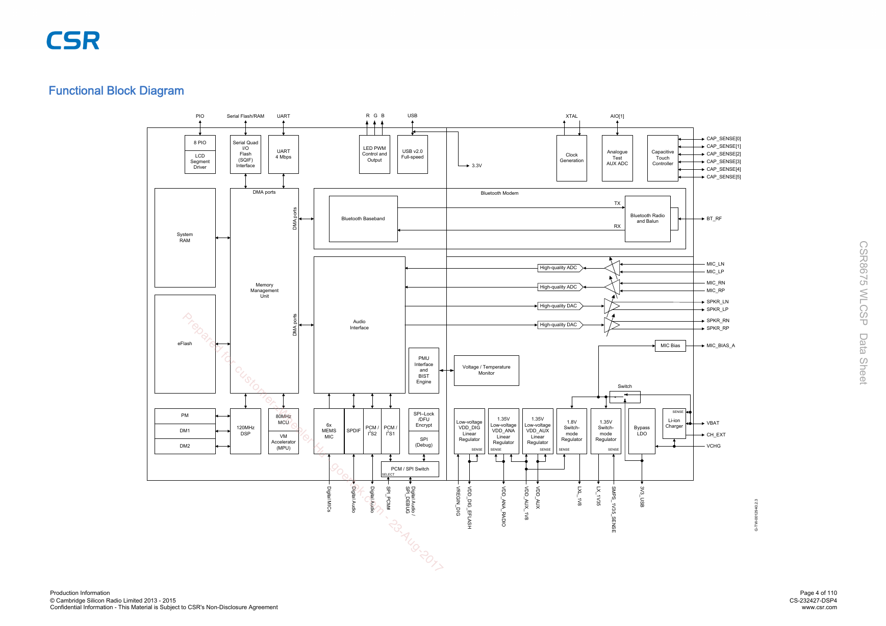
Functional Block Diagram
Document History
Status Information
Contents
List of Figures
List of Tables
List of Equations
1 Package Information
1.1 Pinout Diagram
1.2 Device Terminal Functions
1.3 Package Dimensions
1.4 PCB Design and Assembly Considerations
1.5 Typical Solder Reflow Profile
2 System Architecture
3 Bluetooth Modem
3.1 RF Ports
3.1.1 BT_RF
3.2 RF Receiver
3.2.1 Low Noise Amplifier
3.2.2 RSSI Analogue to Digital Converter
3.3 RF Transmitter
3.3.1 IQ Modulator
3.3.2 Power Amplifier
3.4 Bluetooth Radio Synthesiser
3.5 Baseband
3.5.1 Burst Mode Controller
3.5.2 Physical Layer Hardware Engine
4 Clock Generation
4.1 Clock Architecture
4.2 Input Frequencies and PS Key Settings
4.3 External Reference Clock
4.3.1 Input: XTAL_IN
4.3.2 XTAL_IN Impedance in External Mode
4.3.3 Clock Timing Accuracy
4.4 Crystal Oscillator: XTAL_IN and XTAL_OUT
4.4.1 Crystal Calibration
4.4.2 Crystal Specification
5 Bluetooth Stack Microcontroller
5.1 VM Accelerator
6 Kalimba DSP
7 Memory Interface and Management
7.1 Memory Management Unit
7.2 System RAM
7.3 Kalimba DSP RAM
7.4 eFlash Memory (16 Mb)
7.5 Serial Quad I/O Flash Interface (SQIF)
8 Serial Interfaces
8.1 USB Interface
8.2 UART Interface
8.2.1 UART Configuration While Reset is Active
8.3 Programming and Debug Interface
8.3.1 Instruction Cycle
8.3.2 Multi-slave Operation
8.3.3 SPI-lock
8.4 Software-driven I²C Interface
9 Interfaces
9.1 Programmable I/O Ports, PIO
9.2 Analogue I/O Ports, AIO
9.3 Capacitive Touch Sensor
9.3.1 Capacitive Range Control:
9.3.2 Sampling Front End
9.3.3 ADC
9.3.4 Digital Signal Conditioning (Digital Processing)
9.3.5 Software Signal Conditioning (Firmware)
9.3.6 VM
9.4 LED Drivers
10 Audio Interface
10.1 Audio Input and Output
10.2 Audio Codec Interface
10.2.1 Audio Codec Block Diagram
10.2.2 Codec Set-up
10.2.3 ADC
10.2.4 ADC Sample Rate Selection
10.2.5 ADC Audio Input Gain
10.2.6 ADC Pre-amplifier and ADC Analogue Gain
10.2.7 ADC Digital Gain
10.2.8 ADC Digital IIR Filter
10.2.9 DAC
10.2.10 DAC Sample Rate Selection
10.2.11 DAC Digital Gain
10.2.12 DAC Analogue Gain
10.2.13 DAC Digital FIR Filter
10.2.14 IEC 60958 Interface
10.2.15 Microphone Input
10.2.16 Digital Microphone Inputs
10.2.17 Line Input
10.2.18 Output Stage
10.2.19 Mono Operation
10.2.20 Side Tone
10.2.21 Integrated Digital IIR Filter
10.3 PCM1 and PCM2 Interface
10.3.1 PCM Interface Master/Slave
10.3.2 Long Frame Sync
10.3.3 Short Frame Sync
10.3.4 Multi-slot Operation
10.3.5 GCI Interface
10.3.6 Slots and Sample Formats
10.3.7 Additional Features
10.3.8 PCM Timing Information
10.3.9 PCM_CLK and PCM_SYNC Generation
10.3.10 PCM Configuration
10.4 I²S1 and I²S2 Interface
11 WLAN Coexistence Interface
12 Power Control and Regulation
12.1 1.8V Switch-mode Regulator
12.2 1.35V Switch-mode Regulator
12.3 Inductor Choice
12.4 1.8V and 1.35V Switch-mode Regulators Combined
12.5 Bypass LDO Linear Regulator
12.6 Low-voltage VDD_DIG Linear Regulator
12.7 Low-voltage VDD_AUX Linear Regulator
12.8 Low-voltage VDD_ANA Linear Regulator
12.9 Voltage Regulator Enable
12.10 External Regulators and Power Sequencing
12.11 Reset, RST#
12.11.1 Digital Pin States on Reset
12.11.2 Status After Reset
12.12 Automatic Reset Protection
13 Battery Charger
13.1 Battery Charger Hardware Operating Modes
13.1.1 Disabled Mode
13.1.2 Trickle Charge Mode
13.1.3 Fast Charge Mode
13.1.4 Standby Mode
13.1.5 Error Mode
13.2 Battery Charger Trimming and Calibration
13.3 VM Battery Charger Control
13.4 Battery Charger Firmware and PS Keys
13.5 External Mode
14 Example Application Schematic
15 Example Application Using Different Power Supply Configurations
16 Electrical Characteristics
16.1 Absolute Maximum Ratings
16.2 Recommended Operating Conditions
16.3 Input/Output Terminal Characteristics
16.3.1 Regulators: Available For External Use
16.3.1.1 1.8V Switch-mode Regulator
16.3.1.2 Combined 1.8V and 1.35V Switch-mode Regulator
16.3.1.3 Bypass LDO Regulator
16.3.2 Regulators: For Internal Use Only
16.3.2.1 1.35V Switch-mode Regulator
16.3.2.2 Low-voltage VDD_DIG Linear Regulator
16.3.2.3 Low-voltage VDD_AUX Linear Regulator
16.3.2.4 Low-voltage VDD_ANA Linear Regulator
16.3.3 Regulator Enable
16.3.4 Battery Charger
16.3.5 Reset
16.3.6 USB
16.3.7 Clocks
16.3.8 Stereo Codec: Analogue to Digital Converter
16.3.9 Stereo Codec: Digital to Analogue Converter
16.3.10 Digital
16.3.11 LED Driver Pads
16.3.12 Auxiliary ADC
16.3.13 Auxiliary DAC
16.4 ESD Protection
16.4.1 USB Electrostatic Discharge Immunity
17 Power Consumption
18 CSR Green Semiconductor Products and RoHS Compliance
19 Software
19.1 On-chip Software
19.1.1 Stand-alone CSR8675 WLCSP and Kalimba DSP Applications
19.1.2 BlueCore HCI Stack
19.1.2.1 Latest Features of the HCI Stack
19.2 Off-chip Software
19.2.1 CSR8675 Development Kit
19.2.1.1 Audio Development Kit Software
19.2.2 eXtension Program Support
20 Tape and Reel Information
20.1 Tape Orientation
20.2 Tape Dimensions
20.3 Reel Information
20.4 Moisture Sensitivity Level
21 Document References
Terms and Definitions
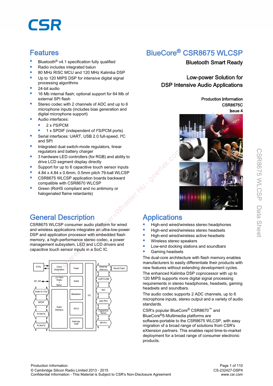
BlueCore® Low-power Solution for Bluetooth® v4.1 specification fully qualified Radio includes integrated balun 80 MHz RISC MC≥ and 120 MHz Kalimba DSP ≥p to 120 MIPS DSP for intensive digital signal processing algorithms 24-bit audio 16 Mb internal flash; optional support for 64 Mb of external SPI flash Stereo codec with 2 channels of ADC and up to 6 microphone inputs (includes bias generation and digital microphone support) Audio interfaces: 2 x I²S/PCM 1 x SPDIF (independent of I²S/PCM ports) Serial interfaces: ≥AR≤, ≥SB 2.0 full-speed, I²C and SPI Integrated dual switch-mode regulators, linear regulators and battery charger 3 hardware LED controllers (for RGB) and ability to drive LCD segment display directly Support for up to 6 capacitive touch sensor inputs 4.84 x 4.84 x 0.6mm, 0.5mm pitch 79-ball WLCSP CSR8675 WLCSP application boards backward compatible with CSR8670 WLCSP Green (RoHS compliant and no antimony or halogenated flame retardants) Prepared for custo m er= W heeler Hu - goertek.co m - 23-Aug-2017 External Memory Serial Flash Flash Clock Generation CSR8675 WLCSP consumer audio platform for wired and wireless applications integrates an ultralowpower DSP and application processor with embedded flash memory, a high-performance stereo codec, a power management subsystem, LED and LCD drivers and capacitive touch sensor inputs in a SoC IC. X≤AL B≤_RF Audio In /Out SPDIF PCM/I2S PCM/I2S 2.4 GHz Radio + Balun RAM Baseband I/O Audio Interface MC≥ Kalimba DSP ≥AR≤/≥SB PIO LED /PIO Capacitive Sense SPI/I2C Low-end docking stations and soundbars High-end wired/wireless stereo headphones High-end wired/wireless stereo headsets High-end wired/wireless active headsets Wireless stereo speakers Gaming headsets ≤he dual-core architecture with flash memory enables manufacturers to easily differentiate their products with new features without extending development cycles. ≤he enhanced Kalimba DSP coprocessor with up to 120 MIPS supports more digital signal processing requirements in stereo headphones, headsets, gaming headsets and soundbars. ≤he audio codec supports 2 ADC channels, up to 6 microphone inputs, stereo output and a variety of audio standards. CSR's popular BlueCore® CSR8670 and BlueCore®5Multimedia platforms are softwareportable to the CSR8675 WLCSP, with easy migration of a broad range of solutions from CSR's eXtension partners. ≤his enables rapid time-to-market deployment for a broad range of consumer electronic products. Production Information © Cambridge Silicon Radio Limited 2013 - 2015 Confidential Information - ≤his Material is Subject to CSR's Non-Disclosure Agreement Page 1 of 110 CS-232427-DSP4 www.csr.com C S R 8 6 7 5 W L C S P D a a S h e e t t
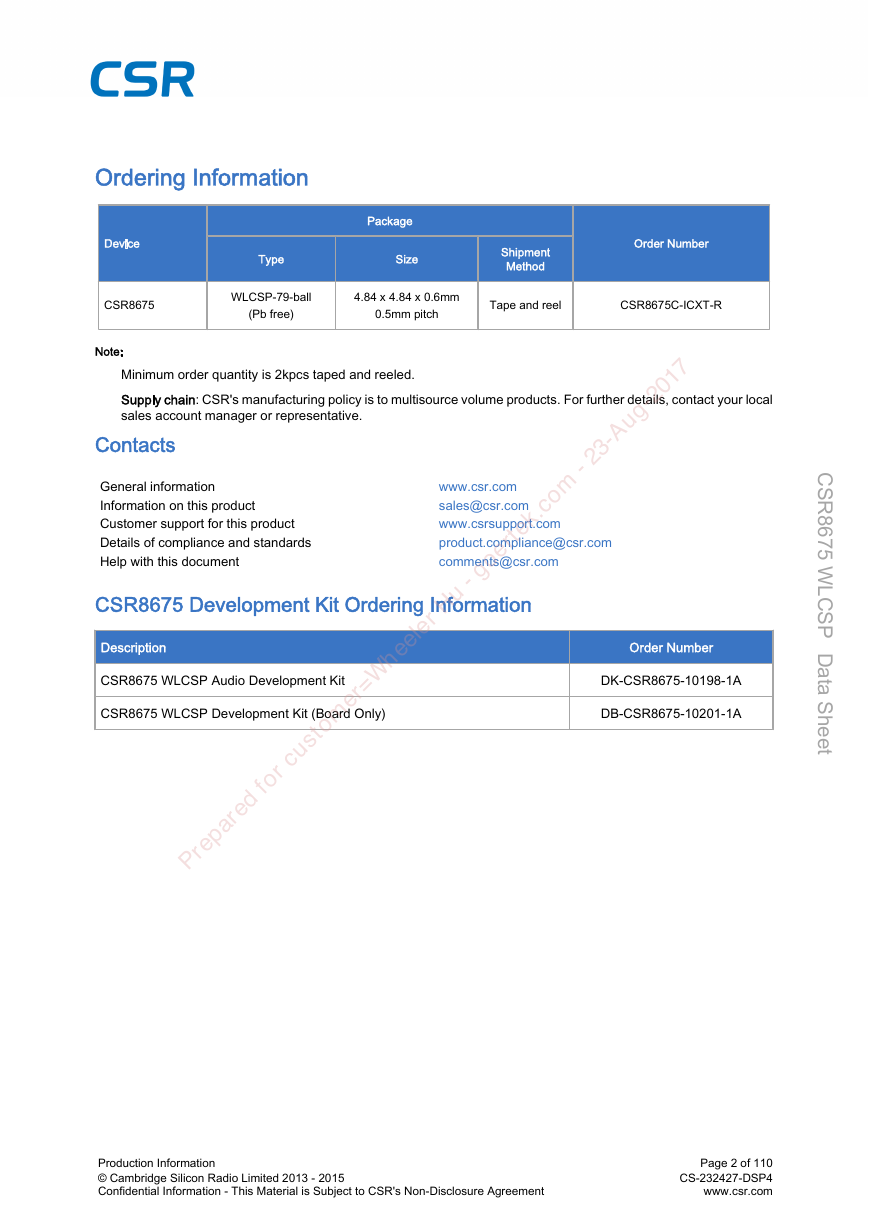
CSR8675 WLCSP79-ball (Pb free) 4.84 x 4.84 x 0.6mm 0.5mm pitch ≤ape and reel CSR8675CICX≤R Minimum order quantity is 2kpcs taped and reeled. : CSR's manufacturing policy is to multisource volume products. For further details, contact your local sales account manager or representative. General information Information on this product Customer support for this product Details of compliance and standards Help with this document www.csr.com sales@csr.com www.csrsupport.com product.compliance@csr.com comments@csr.com Prepared for custo m er= W heeler Hu - goertek.co m - 23-Aug-2017 CSR8675 WLCSP Audio Development Kit CSR8675 WLCSP Development Kit (Board Only) DKCSR8675101981A DBCSR8675102011A C S R 8 6 7 5 W L C S P D a a S h e e t t Production Information © Cambridge Silicon Radio Limited 2013 - 2015 Confidential Information - ≤his Material is Subject to CSR's Non-Disclosure Agreement Page 2 of 110 CS-232427-DSP4 www.csr.com
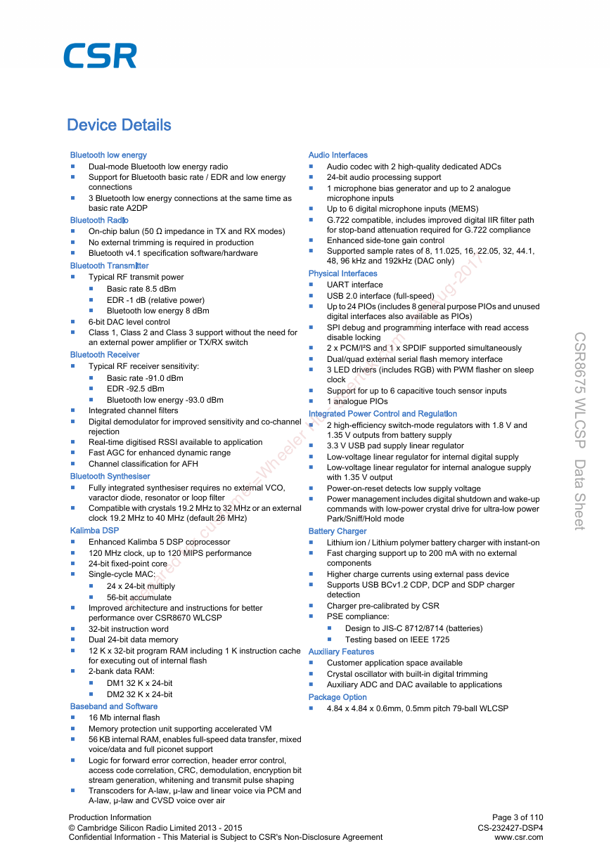
Dualmode Bluetooth low energy radio Support for Bluetooth basic rate / EDR and low energy connections 3 Bluetooth low energy connections at the same time as basic rate A2DP Onchip balun (50 impedance in ≤X and RX modes) No external trimming is required in production Bluetooth v4.1 specification software/hardware Audio codec with 2 highquality dedicated ADCs 24-bit audio processing support 1 microphone bias generator and up to 2 analogue microphone inputs ≥p to 6 digital microphone inputs (MEMS) G.722 compatible, includes improved digital IIR filter path for stopband attenuation required for G.722 compliance Enhanced sidetone gain control Supported sample rates of 8, 11.025, 16, 22.05, 32, 44.1, 48, 96 kHz and 192kHz (DAC only) Basic rate -91.0 dBm EDR -92.5 dBm Bluetooth low energy -93.0 dBm ≥AR≤ interface ≥SB 2.0 interface (fullspeed) ≥p to 24 PIOs (includes 8 general purpose PIOs and unused digital interfaces also available as PIOs) SPI debug and programming interface with read access disable locking 2 x PCM/I²S and 1 x SPDIF supported simultaneously Dual/quad external serial flash memory interface 3 LED drivers (includes RGB) with PWM flasher on sleep clock Support for up to 6 capacitive touch sensor inputs 1 analogue PIOs Basic rate 8.5 dBm EDR -1 dB (relative power) Bluetooth low energy 8 dBm ≤ypical RF transmit power 6bit DAC level control Class 1, Class 2 and Class 3 support without the need for an external power amplifier or ≤X/RX switch ≤ypical RF receiver sensitivity: Integrated channel filters Digital demodulator for improved sensitivity and cochannel rejection Realtime digitised RSSI available to application Fast AGC for enhanced dynamic range Channel classification for AFH Prepared for custo m er= W heeler Hu - goertek.co m - 23-Aug-2017 Fully integrated synthesiser requires no external VCO, varactor diode, resonator or loop filter Compatible with crystals 19.2 MHz to 32 MHz or an external clock 19.2 MHz to 40 MHz (default 26 MHz) 2 highefficiency switchmode regulators with 1.8 V and 1.35 V outputs from battery supply 3.3 V ≥SB pad supply linear regulator Lowvoltage linear regulator for internal digital supply Lowvoltage linear regulator for internal analogue supply with 1.35 V output Poweronreset detects low supply voltage Power management includes digital shutdown and wakeup commands with lowpower crystal drive for ultralow power Park/Sniff/Hold mode Lithium ion / Lithium polymer battery charger with instanton Fast charging support up to 200 mA with no external components Higher charge currents using external pass device Supports ≥SB BCv1.2 CDP, DCP and SDP charger detection Charger precalibrated by CSR PSE compliance: Design to JISC 8712/8714 (batteries) ≤esting based on IEEE 1725 24 x 24bit multiply 56bit accumulate Enhanced Kalimba 5 DSP coprocessor 120 MHz clock, up to 120 MIPS performance 24bit fixed-point core Singlecycle MAC: Improved architecture and instructions for better performance over CSR8670 WLCSP 32bit instruction word Dual 24bit data memory 12 K x 32bit program RAM including 1 K instruction cache for executing out of internal flash 2bank data RAM: DM1 32 K x 24bit DM2 32 K x 24bit Customer application space available Crystal oscillator with builtin digital trimming Auxiliary ADC and DAC available to applications 4.84 x 4.84 x 0.6mm, 0.5mm pitch 79-ball WLCSP C S R 8 6 7 5 W L C S P D a a S h e e t t 16 Mb internal flash Memory protection unit supporting accelerated VM 56 KB internal RAM, enables fullspeed data transfer, mixed voice/data and full piconet support Logic for forward error correction, header error control, access code correlation, CRC, demodulation, encryption bit stream generation, whitening and transmit pulse shaping ≤ranscoders for Alaw, µlaw and linear voice via PCM and Alaw, µlaw and CVSD voice over air Production Information © Cambridge Silicon Radio Limited 2013 - 2015 Confidential Information - ≤his Material is Subject to CSR's Non-Disclosure Agreement Page 3 of 110 CS-232427-DSP4 www.csr.com
PIO Serial Flash/RAM UART R G B USB XTAL AIO[1] 8 PIO Serial Quad LCD Segment Driver I/O Flash (SQIF) Interface UART 4 Mbps LED PWM Control and Output USB v2.0 Full-speed 3.3V Clock Generation Analogue Test AUX ADC Capacitive Touch Controller CAP_SENSE[0] CAP_SENSE[1] CAP_SENSE[2] CAP_SENSE[3] CAP_SENSE[4] CAP_SENSE[5] DMA ports Bluetooth Modem s t r o p A M D s t r o p A M D Memory Management Unit Bluetooth Baseband Audio Interface System RAM eFlash PM DM1 DM2 P r e p a r e d f o r c u s t o m e r = W 80MHz MCU h e 120MHz DSP VM ele r H Accelerator (MPU) 6x MEMS MIC SPDIF PCM / I2S2 PCM / I2S1 u - g o e rt e D g i D g i i t a l I M C s PCM / SPI Switch SELECT k.c a i t l D g i I S P _ P C M # m A u d o i o i t a l A u d o i I S P _ D E B U G D g i i t a l A u d o i / - 2 3 - A TX RX Bluetooth Radio and Balun BT_RF High-quality ADC High-quality ADC High-quality DAC High-quality DAC MIC_LN MIC_LP MIC_RN MIC_RP SPKR_LN SPKR_LP SPKR_RN SPKR_RP MIC Bias MIC_BIAS_A Voltage / Temperature Monitor C S R 8 6 7 5 W L C S P D a a S h e e t Switch t Low-voltage VDD_DIG Linear Regulator 1.35V Low-voltage VDD_ANA Linear Regulator 1.35V Low-voltage VDD_AUX Linear Regulator 1.8V Switch- mode 1.35V Switch- mode Regulator Regulator Bypass LDO SENSE SENSE SENSE SENSE SENSE SENSE Li-ion Charger VBAT CH_EXT VCHG PMU Interface and BIST Engine SPILock /DFU Encrypt SPI (Debug) I V R E G N _ D G I I V D D _ D G _ E F L A S H V D D _ A N A _ R A D O I V D D _ A U X V D D _ A U X _ 1 V 8 3 V 3 _ U S B L X L _ 1 V 8 L X _ 1 V 3 5 S M P S _ 1 V 3 5 _ S E N S E 3 . 2 . 0 4 9 2 1 0 0 - W T - G Production Information © Cambridge Silicon Radio Limited 2013 - 2015 Confidential Information - ≤his Material is Subject to CSR's Non-Disclosure Agreement Page 4 of 110 CS-232427-DSP4 www.csr.com u g - 2 0 1 7
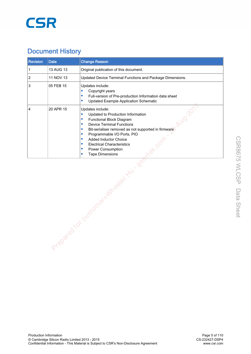
1 2 3 4 13 A≥G 13 11 NOV 13 05 FEB 15 20 APR 15 Original publication of this document. ≥pdated Device ≤erminal Functions and Package Dimensions. ≥pdates include: Copyright years Full-version of Pre-production Information data sheet ≥pdated Example Application Schematic ≥pdates include: ≥pdated to Production Information Functional Block Diagram Device ≤erminal Functions Bit-serialiser removed as not supported in firmware Programmable I/O Ports, PIO Added Inductor Choice Electrical Characteristics Power Consumption ≤ape Dimensions Prepared for custo m er= W heeler Hu - goertek.co m - 23-Aug-2017 C S R 8 6 7 5 W L C S P D a a S h e e t t Production Information © Cambridge Silicon Radio Limited 2013 - 2015 Confidential Information - ≤his Material is Subject to CSR's Non-Disclosure Agreement Page 5 of 110 CS-232427-DSP4 www.csr.com
≤he status of this Data Sheet is Production Information. CSR Product Data Sheets progress according to the following format: Information for designers concerning CSR product in development. All values specified are the target values of the design. Minimum and maximum values specified are only given as guidance to the final specification limits and must not be considered as the final values. Information about initial devices. Devices are untested or partially tested prototypes, their status is described in an Engineering Sample Release Note. All values specified are the target values of the design. Minimum and maximum values specified are only given as guidance to the final specification limits and must not be considered as the final values. All detailed specifications including pinouts and electrical specifications may be changed by CSR without notice. Pinout and mechanical dimension specifications finalised. All values specified are the target values of the design. Minimum and maximum values specified are only given as guidance to the final specification limits and must not be considered as the final values. All electrical specifications may be changed by CSR without notice. As the feature-set of the CSR8675 WLCSP is firmware build-specific, see the relevant software release note for the exact implementation of features on the CSR8675 WLCSP. Life Support Policy and ≥se in Safety-critical Applications CSR's products are not authorised for use in life-support or safety-critical applications. ≥se in such applications is done at the sole discretion of the customer. CSR will not warrant the use of its devices in such applications. Final Data Sheet including the guaranteed minimum and maximum limits for the electrical specifications. Production Data Sheets supersede all previous document versions. Prepared for custo m er= W heeler Hu - goertek.co m - 23-Aug-2017 ≥nless otherwise stated, words and logos marked with or ® are trademarks registered or owned by CSR plc or its affiliates. Bluetooth ® and the Bluetooth ® logos are trademarks owned by Bluetooth ® SIG, Inc. and licensed to CSR. Other products, services and names used in this document may have been trademarked by their respective owners. ≤he publication of this information does not imply that any license is granted under any patent or other rights owned by CSR plc and/or its affiliates. CSR reserves the right to make technical changes to its products as part of its development programme. While every care has been taken to ensure the accuracy of the contents of this document, CSR cannot accept responsibility for any errors. Refer to www.csrsupport.com for compliance and conformance to standards information. CSR8675 WLCSP devices meet the requirements of Directive 2011/65/E≥ of the European Parliament and of the Council on the Restriction of Hazardous Substance (RoHS). CSR8675 WLCSP devices are free from halogenated or antimony trioxide-based flame retardants and other hazardous chemicals. For more information, see CSR's Environmental Compliance Statement for CSR Green Semiconductor Products. C S R 8 6 7 5 W L C S P D a a S h e e t t Production Information © Cambridge Silicon Radio Limited 2013 - 2015 Confidential Information - ≤his Material is Subject to CSR's Non-Disclosure Agreement Page 6 of 110 CS-232427-DSP4 www.csr.com
Contacts ..................................................................................................................................................... 2 CSR8675 Development Kit Ordering Information ...................................................................................... 2 3.1.1 3.5.1 3.5.2 3.3.1 3.3.2 3.2.1 3.2.2 1.1 Pinout Diagram ........................................................................................................................................ 13 1.2 Device ≤erminal Functions ....................................................................................................................... 14 1.3 Package Dimensions ............................................................................................................................... 20 1.4 PCB Design and Assembly Considerations ............................................................................................. 21 1.5 ≤ypical Solder Reflow Profile ................................................................................................................... 21 3.1 RF Ports ................................................................................................................................................... 23 B≤_RF ........................................................................................................................................ 23 3.2 RF Receiver ............................................................................................................................................. 23 Low Noise Amplifier .................................................................................................................... 23 RSSI Analogue to Digital Converter ........................................................................................... 23 3.3 RF ≤ransmitter ......................................................................................................................................... 23 IQ Modulator ............................................................................................................................... 23 Power Amplifier .......................................................................................................................... 24 3.4 Bluetooth Radio Synthesiser .................................................................................................................... 24 3.5 Baseband ................................................................................................................................................. 24 Burst Mode Controller ................................................................................................................. 24 Physical Layer Hardware Engine ............................................................................................... 24 Prepared for custo m er= W heeler Hu - goertek.co m - 23-Aug-2017 4.1 Clock Architecture .................................................................................................................................... 25 4.2 Input Frequencies and PS Key Settings .................................................................................................. 25 4.3 External Reference Clock ........................................................................................................................ 25 Input: X≤AL_IN ........................................................................................................................... 25 X≤AL_IN Impedance in External Mode ...................................................................................... 26 Clock ≤iming Accuracy ............................................................................................................... 26 4.4 Crystal Oscillator: X≤AL_IN and X≤AL_O≥≤ ........................................................................................... 27 Crystal Calibration ...................................................................................................................... 27 Crystal Specification ................................................................................................................... 27 4.3.1 4.3.2 4.3.3 4.4.1 4.4.2 5.1 VM Accelerator ......................................................................................................................................... 28 7.1 Memory Management ≥nit ....................................................................................................................... 30 7.2 System RAM ............................................................................................................................................ 30 7.3 Kalimba DSP RAM ................................................................................................................................... 30 7.4 eFlash Memory (16 Mb) ........................................................................................................................... 30 7.5 Serial Quad I/O Flash Interface (SQIF) .................................................................................................... 30 8.1 ≥SB Interface ........................................................................................................................................... 32 8.2 ≥AR≤ Interface ........................................................................................................................................ 32 ≥AR≤ Configuration While Reset is Active ................................................................................. 33 8.3 Programming and Debug Interface .......................................................................................................... 33 8.2.1 Production Information © Cambridge Silicon Radio Limited 2013 - 2015 Confidential Information - ≤his Material is Subject to CSR's Non-Disclosure Agreement Page 7 of 110 CS-232427-DSP4 www.csr.com C S R 8 6 7 5 W L C S P D a a S h e e t t
8.3.1 Instruction Cycle ......................................................................................................................... 34 8.3.2 Multi-slave Operation .................................................................................................................. 34 8.3.3 SPI-lock ...................................................................................................................................... 34 8.4 Software-driven I²C Interface ................................................................................................................... 34 9.1 Programmable I/O Ports, PIO .................................................................................................................. 35 9.2 Analogue I/O Ports, AIO ........................................................................................................................... 36 9.3 Capacitive ≤ouch Sensor ......................................................................................................................... 36 Capacitive Range Control: .......................................................................................................... 37 9.3.1 Sampling Front End .................................................................................................................... 37 9.3.2 ADC ............................................................................................................................................ 38 9.3.3 Digital Signal Conditioning (Digital Processing) ......................................................................... 38 9.3.4 Software Signal Conditioning (Firmware) ................................................................................... 38 9.3.5 VM .............................................................................................................................................. 38 9.3.6 LED Drivers .............................................................................................................................................. 38 9.4 Prepared for custo m er= W heeler Hu - goertek.co m - 23-Aug-2017 10.1 Audio Input and Output ............................................................................................................................ 41 10.2 Audio Codec Interface .............................................................................................................................. 41 10.2.1 Audio Codec Block Diagram ....................................................................................................... 42 10.2.2 Codec Set-up .............................................................................................................................. 42 10.2.3 ADC ............................................................................................................................................ 42 10.2.4 ADC Sample Rate Selection ...................................................................................................... 43 10.2.5 ADC Audio Input Gain ................................................................................................................ 43 10.2.6 ADC Pre-amplifier and ADC Analogue Gain .............................................................................. 43 10.2.7 ADC Digital Gain ........................................................................................................................ 43 10.2.8 ADC Digital IIR Filter .................................................................................................................. 44 10.2.9 DAC ............................................................................................................................................ 44 10.2.10 DAC Sample Rate Selection ...................................................................................................... 44 10.2.11 DAC Digital Gain ........................................................................................................................ 44 10.2.12 DAC Analogue Gain ................................................................................................................... 45 10.2.13 DAC Digital FIR Filter ................................................................................................................. 45 10.2.14 IEC 60958 Interface .................................................................................................................... 45 10.2.15 Microphone Input ........................................................................................................................ 46 10.2.16 Digital Microphone Inputs ........................................................................................................... 47 10.2.17 Line Input .................................................................................................................................... 48 10.2.18 Output Stage .............................................................................................................................. 48 10.2.19 Mono Operation .......................................................................................................................... 49 10.2.20 Side ≤one ................................................................................................................................... 50 10.2.21 Integrated Digital IIR Filter .......................................................................................................... 51 10.3 PCM1 and PCM2 Interface ...................................................................................................................... 52 10.3.1 PCM Interface Master/Slave ....................................................................................................... 52 10.3.2 Long Frame Sync ....................................................................................................................... 53 10.3.3 Short Frame Sync ....................................................................................................................... 54 10.3.4 Multi-slot Operation .................................................................................................................... 54 10.3.5 GCI Interface .............................................................................................................................. 54 10.3.6 Slots and Sample Formats ......................................................................................................... 55 10.3.7 Additional Features ..................................................................................................................... 56 10.3.8 PCM ≤iming Information ............................................................................................................. 56 10.3.9 PCM_CLK and PCM_SYNC Generation .................................................................................... 60 10.3.10 PCM Configuration ..................................................................................................................... 60 10.4 I²S1 and I²S2 Interface ............................................................................................................................. 61 Production Information © Cambridge Silicon Radio Limited 2013 - 2015 Confidential Information - ≤his Material is Subject to CSR's Non-Disclosure Agreement Page 8 of 110 CS-232427-DSP4 www.csr.com C S R 8 6 7 5 W L C S P D a a S h e e t t
分享到:
收藏