BlueCore™
Inverted-F and Meander Line Antennas
Application Note
January 2003
CSR
Unit 400 Cambridge Science Park
Milton Road
Cambridge
CB4 0WH
United Kingdom
Registered in England 3665875
Tel: +44 (0)1223 692000
Fax: +44 (0)1223 692001
www.csr.com
bcant-an-001Pa
This material is subject to CSR’s non-disclosure agreement.
© Copyright CSR 2003
�
Contents
Contents
Introduction.......................................................................................................................................................................3
1
2
Inverted-F Antenna .........................................................................................................................................................4
3 Meander Line Antenna ...................................................................................................................................................5
4 Real Designs.....................................................................................................................................................................6
Proximity to Metal Objects ...........................................................................................................................................7
5
6
Proximity to Dielectric Materials.................................................................................................................................8
7 Network Analyser............................................................................................................................................................9
8
Final Tuning ................................................................................................................................................................... 10
9 Conclusion ..................................................................................................................................................................... 12
Acronyms and Definitions ................................................................................................................................................. 13
Record of Changes.............................................................................................................................................................. 14
List of Figures
Figure 2.1: Inverted-F Antenna...............................................................................................................................................4
Figure 3.1: Meander Line Antenna.........................................................................................................................................5
Figure 3.2: Input Impedance of Two Meander Line Antennas ...........................................................................................5
Figure 4.1: Approximate Dimensions of Inverted-F Antenna.............................................................................................6
Figure 4.2: Approximate Dimensions of Meander Line Antenna.......................................................................................6
Figure 7.1: Preparation Before Measurement......................................................................................................................9
Figure 7.2: Assembled System Ready to Measure.............................................................................................................9
Figure 8.1: Locating Product in Far Field of Antenna....................................................................................................... 10
Figure 8.2: Final Tuning Procedure .................................................................................................................................... 11
bcant-an-001Pa
This material is subject to CSR’s non-disclosure agreement.
© Copyright CSR 2003
Page 2 of 14
B
l
u
e
C
o
r
e
™
I
n
v
e
r
t
e
d
-
F
a
n
d
M
e
a
n
d
e
r
L
n
e
A
n
t
e
n
n
a
s
i
�
Introduction
1
Introduction
This document outlines two types of Printed Circuit Board (PCB) antennas used by CSR.
Inverted-F
§
§ Meander Line
Also discussed in this document is the effect of placing metallic or dielectric materials near an
antenna.
B
l
u
e
C
o
r
e
™
I
n
v
e
r
t
e
d
-
F
a
n
d
M
e
a
n
d
e
r
L
n
e
A
n
t
e
n
n
a
s
i
bcant-an-001Pa
This material is subject to CSR’s non-disclosure agreement.
© Copyright CSR 2003
Page 3 of 14
�
Inverted-F Antenna
2
Inverted-F Antenna
Quarterwave
Input
Output
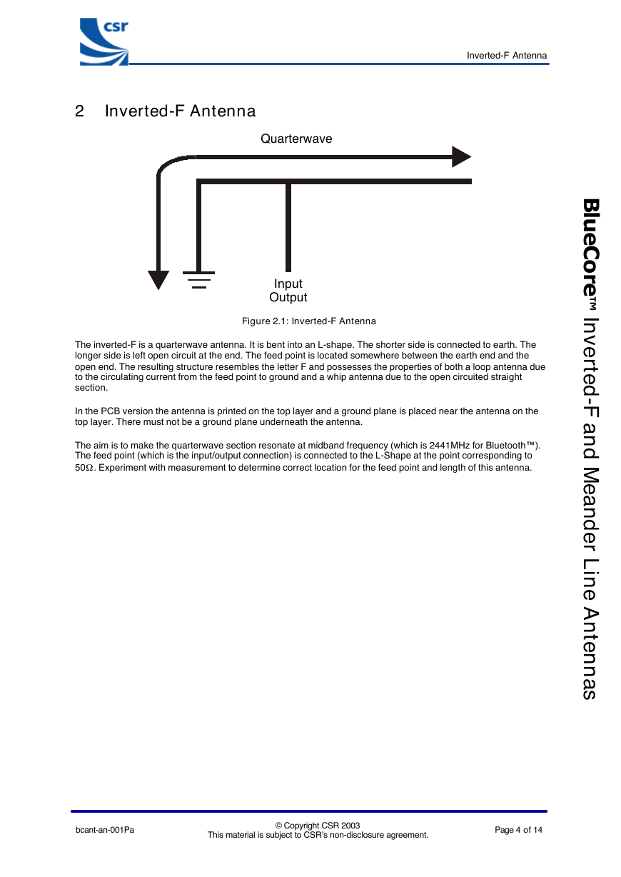
Figure 2.1: Inverted-F Antenna
The inverted-F is a quarterwave antenna. It is bent into an L-shape. The shorter side is connected to earth. The
longer side is left open circuit at the end. The feed point is located somewhere between the earth end and the
open end. The resulting structure resembles the letter F and possesses the properties of both a loop antenna due
to the circulating current from the feed point to ground and a whip antenna due to the open circuited straight
section.
In the PCB version the antenna is printed on the top layer and a ground plane is placed near the antenna on the
top layer. There must not be a ground plane underneath the antenna.
The aim is to make the quarterwave section resonate at midband frequency (which is 2441MHz for Bluetooth™).
The feed point (which is the input/output connection) is connected to the L-Shape at the point corresponding to
50W
. Experiment with measurement to determine correct location for the feed point and length of this antenna.
bcant-an-001Pa
This material is subject to CSR’s non-disclosure agreement.
© Copyright CSR 2003
Page 4 of 14
B
l
u
e
C
o
r
e
™
I
n
v
e
r
t
e
d
-
F
a
n
d
M
e
a
n
d
e
r
L
n
e
A
n
t
e
n
n
a
s
i
�
3 Meander Line Antenna
Meander Line Antenna
S
Ground
Plane
Input
Output
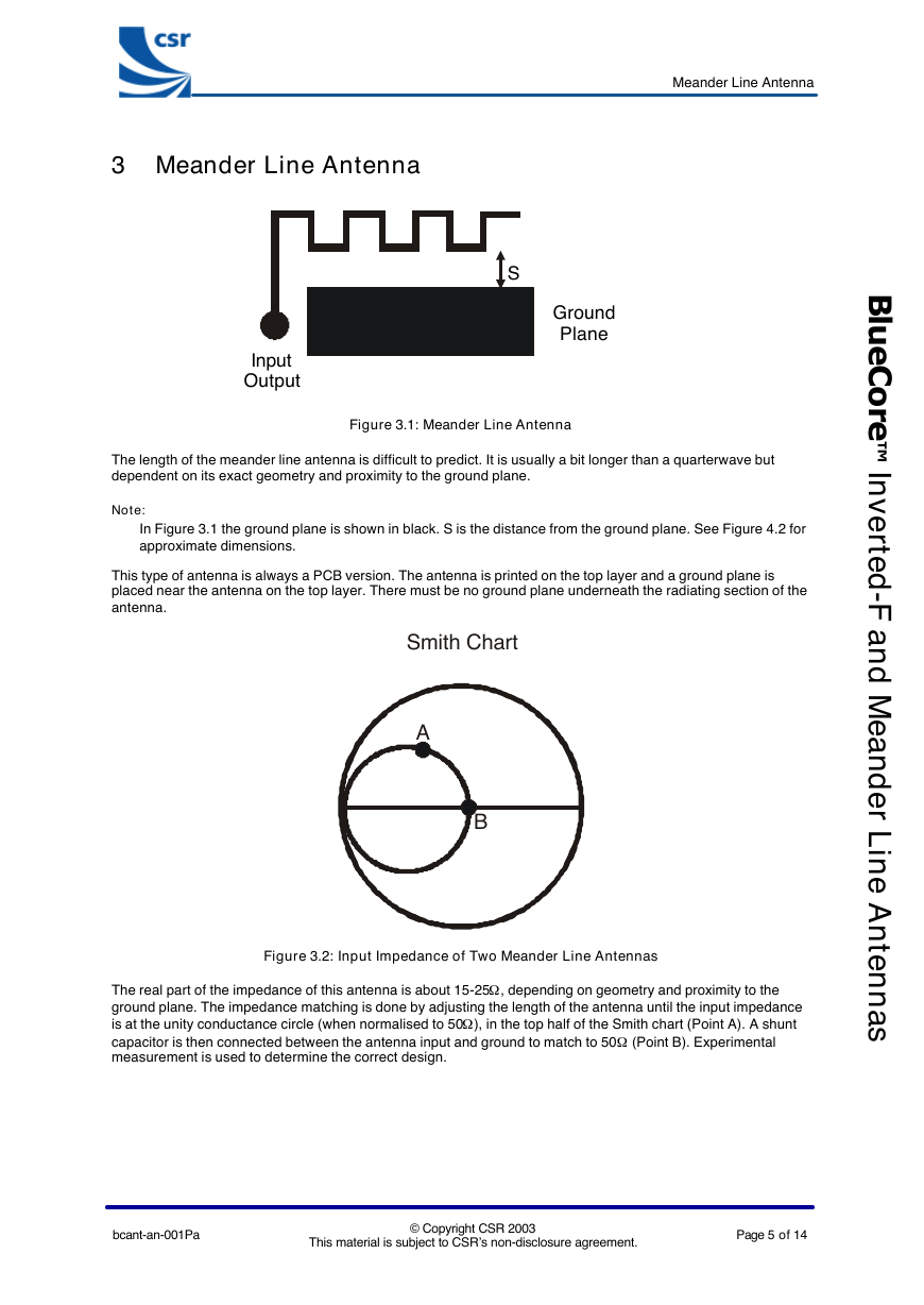
Figure 3.1: Meander Line Antenna
The length of the meander line antenna is difficult to predict. It is usually a bit longer than a quarterwave but
dependent on its exact geometry and proximity to the ground plane.
Note:
In Figure 3.1 the ground plane is shown in black. S is the distance from the ground plane. See Figure 4.2 for
approximate dimensions.
This type of antenna is always a PCB version. The antenna is printed on the top layer and a ground plane is
placed near the antenna on the top layer. There must be no ground plane underneath the radiating section of the
antenna.
Smith Chart
A
B
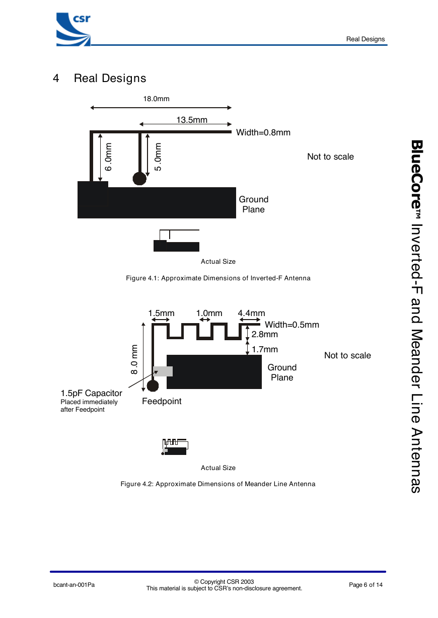
Figure 3.2: Input Impedance of Two Meander Line Antennas
The real part of the impedance of this antenna is about 15-25W
ground plane. The impedance matching is done by adjusting the length of the antenna until the input impedance
is at the unity conductance circle (when normalised to 50W
), in the top half of the Smith chart (Point A). A shunt
capacitor is then connected between the antenna input and ground to match to 50W
measurement is used to determine the correct design.
, depending on geometry and proximity to the
(Point B). Experimental
bcant-an-001Pa
This material is subject to CSR’s non-disclosure agreement.
© Copyright CSR 2003
Page 5 of 14
B
l
u
e
C
o
r
e
™
I
n
v
e
r
t
e
d
-
F
a
n
d
M
e
a
n
d
e
r
L
n
e
A
n
t
e
n
n
a
s
i
�
4 Real Designs
18.0mm
13.5mm
m
m
0
..
6
m
m
0
..
5
Real Designs
Width=0.8mm
Not to scale
Ground
Plane
B
l
u
e
C
o
r
e
™
I
Actual Size
Figure 4.1: Approximate Dimensions of Inverted-F Antenna
1.5mm
1.0mm
4.4mm
m
m
..
0
8
1.5pF Capacitor
Placed immediately
after Feedpoint
Feedpoint
Width=0.5mm
2.8mm
1.7mm
Ground
Plane
Not to scale
Actual Size
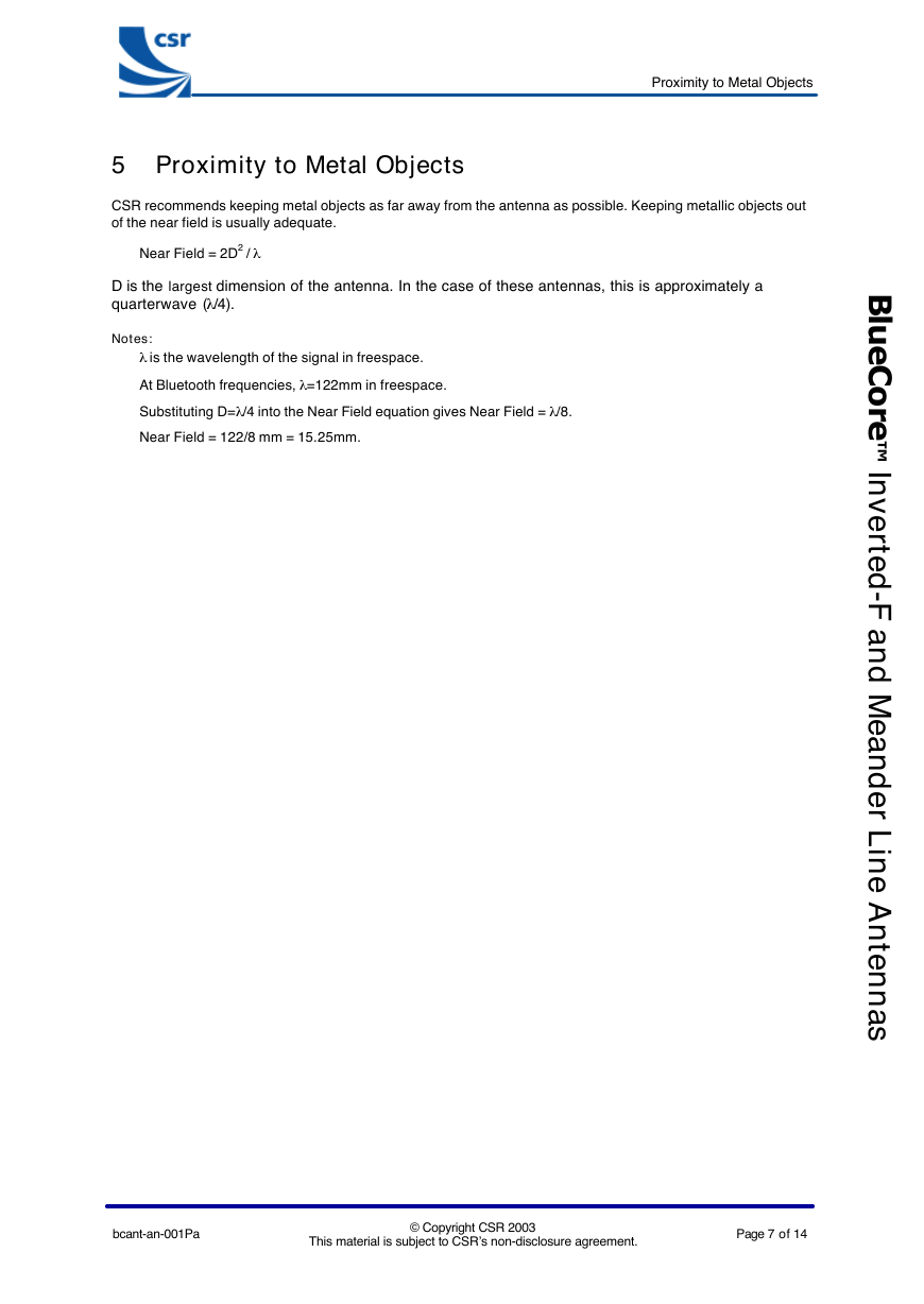
Figure 4.2: Approximate Dimensions of Meander Line Antenna
bcant-an-001Pa
This material is subject to CSR’s non-disclosure agreement.
© Copyright CSR 2003
Page 6 of 14
n
v
e
r
t
e
d
-
F
a
n
d
M
e
a
n
d
e
r
L
n
e
A
n
t
e
n
n
a
s
i
�
Proximity to Metal Objects
5 Proximity to Metal Objects
CSR recommends keeping metal objects as far away from the antenna as possible. Keeping metallic objects out
of the near field is usually adequate.
Near Field = 2D2 / l
D is the largest dimension of the antenna. In the case of these antennas, this is approximately a
quarterwave (l /4).
Notes:
l is the wavelength of the signal in freespace.
At Bluetooth frequencies, l =122mm in freespace.
Substituting D=l /4 into the Near Field equation gives Near Field = l /8.
Near Field = 122/8 mm = 15.25mm.
B
l
u
e
C
o
r
e
™
I
n
v
e
r
t
e
d
-
F
a
n
d
M
e
a
n
d
e
r
L
n
e
A
n
t
e
n
n
a
s
i
bcant-an-001Pa
This material is subject to CSR’s non-disclosure agreement.
© Copyright CSR 2003
Page 7 of 14
�
Proximity to Dielectric Materials
6 Proximity to Dielectric Materials
Dielectric materials (like plastic or FR-4) detune an antenna by lowering its resonant frequency. The effect is not
as serious as placing an antenna next to metal objects and can be corrected by reducing the length of the
antenna. Therefore it is important for the antenna to be tuned when it is in the product. This is done during the
development of the product.
B
l
u
e
C
o
r
e
™
I
n
v
e
r
t
e
d
-
F
a
n
d
M
e
a
n
d
e
r
L
n
e
A
n
t
e
n
n
a
s
i
bcant-an-001Pa
This material is subject to CSR’s non-disclosure agreement.
© Copyright CSR 2003
Page 8 of 14
�


 2023年江西萍乡中考道德与法治真题及答案.doc
 2012年重庆南川中考生物真题及答案.doc
 2013年江西师范大学地理学综合及文艺理论基础考研真题.doc
 2020年四川甘孜小升初语文真题及答案I卷.doc
 2020年注册岩土工程师专业基础考试真题及答案.doc
 2023-2024学年福建省厦门市九年级上学期数学月考试题及答案.doc
 2021-2022学年辽宁省沈阳市大东区九年级上学期语文期末试题及答案.doc
 2022-2023学年北京东城区初三第一学期物理期末试卷及答案.doc
 2018上半年江西教师资格初中地理学科知识与教学能力真题及答案.doc
 2012年河北国家公务员申论考试真题及答案-省级.doc
 2020-2021学年江苏省扬州市江都区邵樊片九年级上学期数学第一次质量检测试题及答案.doc
 2022下半年黑龙江教师资格证中学综合素质真题及答案.doc