logo资料库

S3C2416芯片手册.pdf

第1页 / 共672页
第2页 / 共672页
第3页 / 共672页
第4页 / 共672页
第5页 / 共672页
第6页 / 共672页
第7页 / 共672页
第8页 / 共672页
资料共672页,剩余部分请下载后查看
About this Document
Important Notice
Notification of Revisions
Table of Contents
Lists of Figures
Lists of Tables
01-Overview
1 INTRODUCTION
2 FEATURES
3 BLOCK DIAGRAM
4 PIN ASSIGNMENTS
02-SYSCON
1 OVERVIEW
2 FEATURE
3 BLOCK DIAGRAM
4 FUNCTIONAL DESCRIPTIONS
5 CLOCK MANAGEMENT
6 POWER MANAGEMENT
7 REGISTER DESCRIPTIONS
8 INDIVIDUAL REGISTER DESCRIPTIONS
03-MATRIX & EBI
1 OVERVIEW
2 SPECIAL FUNCTION REGISTERS
04-Bus Priority
1 OVERVIEW
05-SMC
1 OVERVIEW
2 FEATURE
3 BLOCK DIAGRAM
4 SPECIAL REGISTERS
06-DRAMC
1 OVERVIEW
2 BLOCK DIAGRAM
3 MOBILE DRAM INITIALIZATION SEQUENCE
07-Nand Flash
1 OVERVIEW
2 FEATURES
3 BLOCK DIAGRAM
4 BOOT LOADER FUNCTION
5 GPC5/6/7 PIN CONFIGURATION TABLE IN IROM BOOT MODE
6 NAND FLASH MEMORY TIMING
7 NAND FLASH ACCESS
8 DATA REGISTER CONFIGURATION
9 STEPPINGSTONE (8KB IN 64KB SRAM)
10 1BIT / 4BIT / 8BIT ECC (ERROR CORRECTION CODE)
11 MEMORY MAPPING(NAND BOOT AND OTHER BOOT)
12 NAND FLASH MEMORY CONFIGURATION
13 NAND FLASH CONTROLLER SPECIAL REGISTERS
08-DMA controller
1 OVERVIEW
2 DMA REQUEST SOURCES
3 DMA OPERATION
4 DMA SPECIAL REGISTERS
09-Interrupt controller
1 OVERVIEW
2 INTERRUPT CONTROLLER SPECIAL REGISTERS
10-IOport
1 OVERVIEW
2 PORT CONTROL DESCRIPTIONS
Caution
3 I/O PORT CONTROL REGISTER
4 GPIO ALIVE & SLEEP PART
11-Watchdog
1 OVERVIEW
2 WATCHDOG TIMER OPERATION
3 WATCHDOG TIMER SPECIAL REGISTERS
12-PWM Timer
1 OVERVIEW
2 PWM TIMER OPERATION
3 PWM TIMER CONTROL REGISTERS
13-RTC
1 OVERVIEW
NOTES
14-UART
1 OVERVIEW
2 BLOCK DIAGRAM
3 UART SPECIAL REGISTERS
15-USB HOST Controller
1 OVERVIEW
16-USB 2.0 Device
1 OVERVIEW
2 BLOCK DIAGRAM
3 TO ACTIVATE USB PORT1 FOR USB 2.0 FUNCTION
4 SIE (SERIAL INTERFACE ENGINE)
5 UPH (UNIVERSAL PROTOCOL HANDLER)
6 UTMI (USB 2.0 TRANSCEIVER MACROCELL INTERFACE)
7 USB 2.0 FUNCTION CONTROLLER SPECIAL REGISTERS
8 REGISTERS
17-IIC bus interface
1 OVERVIEW
2 IIC-BUS INTERFACE SPECIAL REGISTERS
18-2D
1 INTRODUCTION
2 COLOR FORMAT CONVERSION
3 COMMAND FIFO
4 RENDERING PIPELINE
5 REGISTER DESCRIPTIONS
19-HSSPI
1 OVERVIEW
2 FEATURES
3 SIGNAL DESCRIPTIONS
4 OPERATION
5 SPECIAL FUNCTION REGISTER DESCRIPTIONS
20-HSMMC
1 OVERVIEW
2 FEATURES
3 BLOCK DIAGRAM
4 SEQUENCE
5 SDI SPECIAL REGISTERS
21-LCD controller
1 OVERVIEW
2 FUNCTIONAL DESCRIPTION
3 WINDOW BLENDING
4 VTIME CONTROLLER OPERATION
5 VIRTUAL DISPLAY
6 RGB INTERFACE I/O
7 LCD CPU INTERFACE I/O (i80-SYSTEM I/F)
8 PROGRAMMER’S MODEL
22-TSADC
1 OVERVIEW
2 ADC & TOUCH SCREEN INTERFACE OPERATION
3 ADC AND TOUCH SCREEN INTERFACE SPECIAL REGISTERS
23-IIS Multi Audio Interface
1 OVERVIEW
2 FEATURE
3 SIGNALS
4 BLOCK DIAGRAM
5 FUNCTIONAL DESCRIPTIONS
6 AUDIO SERIAL DATA FORMAT
7 PROGRAMMING GUIDE
8 IIS-BUS INTERFACE SPECIAL REGISTERS
24-AC97 Controller
1 OVERVIEW
2 AC97 CONTROLLER OPERATION
3 OPERATION FLOW CHART
4 AC-LINK DIGITAL INTERFACE PROTOCOL
Slot 0: Tag Phase
Slot 1: Command Address Port
Slot 2: Command Data Port
Slot 3: PCM Playback Left channel
Slot 4: PCM Playback Right channel
Slot 0: Tag Phase
Slot 1: Status Address Port/SLOTREQ bits
Slot 2: Status Data Port
Slot 3: PCM Record Left channel
Slot 4: PCM Right channel audio
Slot 6: Microphone Record Data
5 AC97 POWER-DOWN
6 CODEC RESET
7 AC97 CONTROLLER STATE DIAGRAM
8 AC97 CONTROLLER SPECIAL REGISTERS
25-PCM Audio Interface
1 OVERVIEW
2 PCM AUDIO INTERFACE
3 PCM TIMING
26-ELECTRICAL DATA
1 ABSOLUTE MAXIMUM RATINGS
2 RECOMMENDED OPERATING CONDITIONS
3 D.C. ELECTRICAL CHARACTERISTICS
4 A.C. ELECTRICAL CHARACTERISTICS
27-MECHANICAL DATA
1 PACKAGE DIMENSIONS
USER'S MANUAL S3C2416 16/32-Bit RISC Microprocessor October 2008 REV 1.10 Confidential Proprietary of Samsung Electronics Co., Ltd Copyright © 2008 Samsung Electronics, Inc. All Rights Reserved
Important Notice The information in this publication has been carefully checked and is believed to be entirely accurate at the time of publication. Samsung assumes no responsibility, however, for possible errors or omissions, or for any consequences resulting from the use of the information contained herein. Samsung reserves the right to make changes in its products or product specifications with the intent to improve function or design at any time and without notice and is not required to update this documentation to reflect such changes. This publication does not convey to a purchaser of semiconductor devices described herein any license under the patent rights of Samsung or others. Samsung makes no warranty, representation, or guarantee regarding the suitability of its products for any particular purpose, nor does Samsung assume any liability arising out of the application or use of any product or circuit and specifically disclaims any and all liability, including without limitation any consequential or incidental damages. S3C2416 16/32-Bit RISC Microprocessor User's Manual, Revision 1.10 Publication Number: 21.10-S3-C2416- 082008 Copyright © 2008 Samsung Electronics Co.,Ltd. "Typical" parameters can and do vary in different applications. All operating parameters, including "Typicals" must be validated for each customer application by the customer's technical experts. Samsung products are not designed, intended, or authorized for use as components in systems intended for surgical implant into the body, for other applications intended to support or sustain life, or for any other application in which the failure of the Samsung product could create a situation where personal injury or death may occur. Should the Buyer purchase or use a Samsung product for any such unintended or unauthorized application, the Buyer shall indemnify and hold Samsung and its officers, employees, subsidiaries, affiliates, and distributors harmless against all claims, costs, damages, expenses, and reasonable attorney fees arising out of, either directly or indirectly, any claim of personal injury or death that may be associated with such unintended or unauthorized use, even if such claim alleges that Samsung was negligent regarding the design or manufacture of said product. All rights reserved. No part of this publication may be reproduced, stored in a retrieval system, or transmitted in any form or by any means, electric or mechanical, by photocopying, recording, or otherwise, without the prior written consent of Samsung Electronics. Samsung Electronics' microcontroller business has been awarded full ISO-14001 certification (BSI Certificate No. FM24653). All semiconductor products are designed and manufactured in accordance with the highest quality standards and objectives. Samsung Electronics Co., Ltd. San #24 Nongseo-Dong, Giheung-Gu Yongin-City, Gyeonggi-Do, Korea C.P.O. Box #37, Suwon 446-711 TEL: (82)-(31)-209-4593 FAX: (82)-(31)-209-5324 Home Page: http://www.samsungsemi.com Printed in the Republic of Korea E-Mail: mobilesol.cs@samsung.com
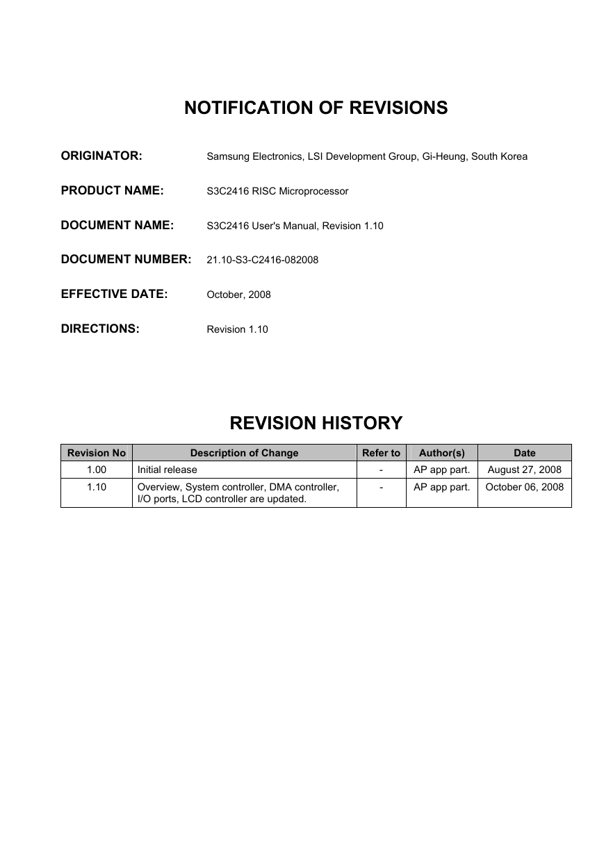
NOTIFICATION OF REVISIONS ORIGINATOR: Samsung Electronics, LSI Development Group, Gi-Heung, South Korea PRODUCT NAME: S3C2416 RISC Microprocessor DOCUMENT NAME: S3C2416 User's Manual, Revision 1.10 DOCUMENT NUMBER: 21.10-S3-C2416-082008 EFFECTIVE DATE: October, 2008 DIRECTIONS: Revision 1.10 REVISION HISTORY Refer to Description of Change Initial release Overview, System controller, DMA controller, I/O ports, LCD controller are updated. - - Revision No 1.00 1.10 Date Author(s) AP app part. August 27, 2008 AP app part. October 06, 2008
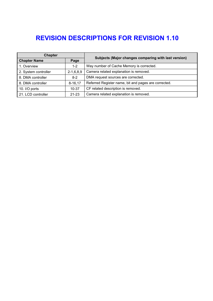
REVISION DESCRIPTIONS FOR REVISION 1.10 Chapter Chapter Name 1. Overview 2. System controller 8. DMA controller 8. DMA controller 10. I/O ports 21. LCD controller Page 1-2 Subjects (Major changes comparing with last version) Way number of Cache Memory is corrected. 2-1,6,8,9 Camera related explanation is removed. 8-2 DMA request sources are corrected. 8-16,17 Referred Register name, bit and pages are corrected. 10-37 21-23 CF related description is removed. Camera related explanation is removed.
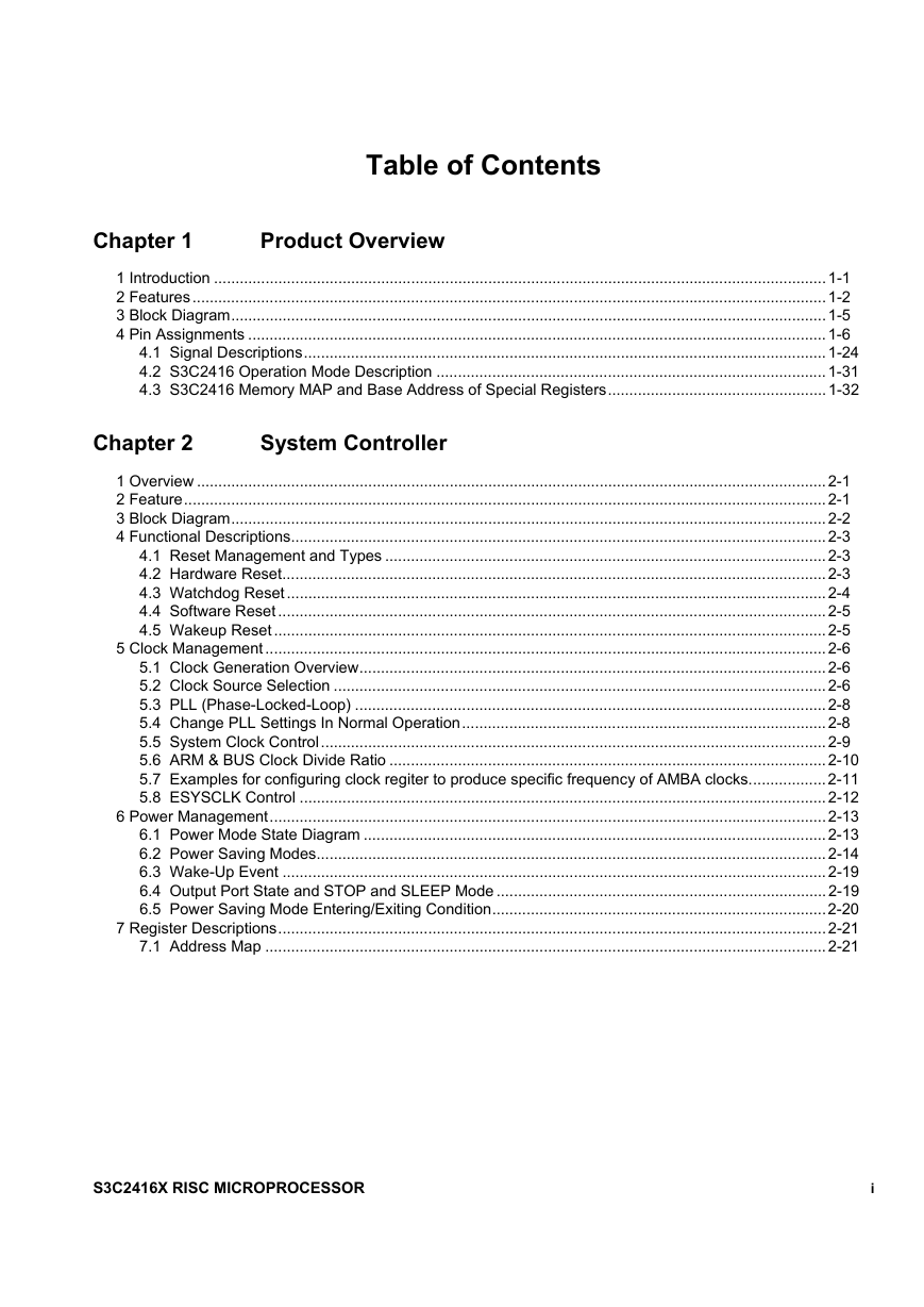
Table of Contents Chapter 1 Product Overview 1 Introduction ...............................................................................................................................................1-1 2 Features....................................................................................................................................................1-2 3 Block Diagram...........................................................................................................................................1-5 4 Pin Assignments .......................................................................................................................................1-6 4.1 Signal Descriptions..........................................................................................................................1-24 4.2 S3C2416 Operation Mode Description ...........................................................................................1-31 4.3 S3C2416 Memory MAP and Base Address of Special Registers...................................................1-32 Chapter 2 System Controller 1 Overview ...................................................................................................................................................2-1 2 Feature......................................................................................................................................................2-1 3 Block Diagram...........................................................................................................................................2-2 4 Functional Descriptions.............................................................................................................................2-3 4.1 Reset Management and Types .......................................................................................................2-3 4.2 Hardware Reset...............................................................................................................................2-3 4.3 Watchdog Reset..............................................................................................................................2-4 4.4 Software Reset ................................................................................................................................2-5 4.5 Wakeup Reset .................................................................................................................................2-5 5 Clock Management ...................................................................................................................................2-6 5.1 Clock Generation Overview.............................................................................................................2-6 5.2 Clock Source Selection ...................................................................................................................2-6 5.3 PLL (Phase-Locked-Loop) ..............................................................................................................2-8 5.4 Change PLL Settings In Normal Operation.....................................................................................2-8 5.5 System Clock Control......................................................................................................................2-9 5.6 ARM & BUS Clock Divide Ratio ......................................................................................................2-10 5.7 Examples for configuring clock regiter to produce specific frequency of AMBA clocks..................2-11 5.8 ESYSCLK Control ...........................................................................................................................2-12 6 Power Management..................................................................................................................................2-13 6.1 Power Mode State Diagram ............................................................................................................2-13 6.2 Power Saving Modes.......................................................................................................................2-14 6.3 Wake-Up Event ...............................................................................................................................2-19 6.4 Output Port State and STOP and SLEEP Mode .............................................................................2-19 6.5 Power Saving Mode Entering/Exiting Condition..............................................................................2-20 7 Register Descriptions................................................................................................................................2-21 7.1 Address Map ...................................................................................................................................2-21 S3C2416X RISC MICROPROCESSOR i
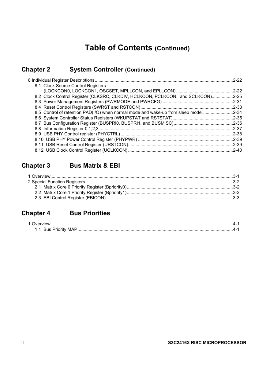
Table of Contents (Continued) Chapter 2 System Controller (Continued) 8 Individual Register Descriptions................................................................................................................2-22 8.1 Clock Source Control Registers (LOCKCON0, LOCKCON1, OSCSET, MPLLCON, and EPLLCON) ..............................................2-22 8.2 Clock Control Register (CLKSRC, CLKDIV, HCLKCON, PCLKCON, and SCLKCON).................2-25 8.3 Power Management Registers (PWRMODE and PWRCFG) .........................................................2-31 8.4 Reset Control Registers (SWRST and RSTCON)...........................................................................2-33 8.5 Control of retention PAD(I/O) when normal mode and wake-up from sleep mode.........................2-34 8.6 System Controller Status Registers (WKUPSTAT and RSTSTAT).................................................2-35 8.7 Bus Configuration Register (BUSPRI0, BUSPRI1, and BUSMISC)................................................2-36 8.8 Information Register 0,1,2,3 ............................................................................................................2-37 8.9 USB PHY Control register (PHYCTRL) ...........................................................................................2-38 8.10 USB PHY Power Control Register (PHYPWR) .............................................................................2-39 8.11 USB Reset Control Register (URSTCON).....................................................................................2-39 8.12 USB Clock Control Register (UCLKCON) .....................................................................................2-40 Chapter 3 Bus Matrix & EBI 1 Overview....................................................................................................................................................3-1 2 Special Function Registers .......................................................................................................................3-2 2.1 Matrix Core 0 Priority Register (Bpriority0)......................................................................................3-2 2.2 Matrix Core 1 Priority Register (Bpriority1)......................................................................................3-2 2.3 EBI Control Register (EBICON).......................................................................................................3-3 Chapter 4 Bus Priorities 1 Overview....................................................................................................................................................4-1 1.1 Bus Priority MAP..............................................................................................................................4-1 ii S3C2416X RISC MICROPROCESSOR
Table of Contents (Continued) Chapter 5 Static Memory Controller (SMC) 1 Overview ...................................................................................................................................................5-1 2 Feature......................................................................................................................................................5-2 3 Block Diagram...........................................................................................................................................5-3 3.1 Asynchronous Read ........................................................................................................................5-4 3.2 Asynchronous Burst Read...............................................................................................................5-6 3.3 Synchronous Read/Synchronous Burst Read.................................................................................5-7 3.4 Asynchronous Write ........................................................................................................................5-8 3.5 Synchronous Write/ Synchronous Burst Write................................................................................5-10 3.6 Bus Turnaround...............................................................................................................................5-11 4 Special Registers ......................................................................................................................................5-14 4.1 Bank Idle Cycle Control Registers 0-5 ............................................................................................5-14 4.2 Bank Read Wait State Control Registers 0-5..................................................................................5-14 4.3 Bank Write Wait State Control Registers 0-5 ..................................................................................5-15 4.4 Bank Output Enable Assertion Delay Control Registers 0-5...........................................................5-15 4.5 Bank Write Enable Assertion Delay Control Registers 0-5 .............................................................5-16 4.6 Bank Control Registers 0-5 .............................................................................................................5-17 4.7 Bank Onenand Type Selection Register .........................................................................................5-19 4.8 SMC Status Register.......................................................................................................................5-19 4.9 SMC Control Register......................................................................................................................5-20 Chapter 6 Mobile DRAM Controller 1 Overview ...................................................................................................................................................6-1 2 Block Diagram...........................................................................................................................................6-2 3 Mobile DRAM Initialization Sequence.......................................................................................................6-3 3.1 Mobile DRAM(SDRAM or mobile DDR) Initialization Sequence.....................................................6-3 3.2 DDR2 Initialization Sequence..........................................................................................................6-3 3.3 Mobile DRAM Configuration Register .............................................................................................6-8 3.4 Mobile DRAM Control Register .......................................................................................................6-9 3.5 Mobile DRAM Timming Control Register ........................................................................................6-10 3.6 Mobile DRAM (Extended ) Mode RegiSter Set Register.................................................................6-11 3.7 Mobile DRAM Refresh Control Register .........................................................................................6-14 3.8 Mobile DRAM Write Buffer Time out Register.................................................................................6-14 S3C2416X RISC MICROPROCESSOR iii
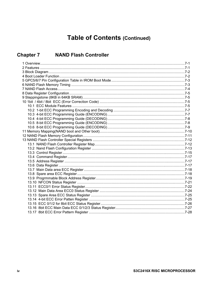
Table of Contents (Continued) Chapter 7 NAND Flash Controller 1 Overview....................................................................................................................................................7-1 2 Features ....................................................................................................................................................7-1 3 Block Diagram ...........................................................................................................................................7-2 4 Boot Loader Function................................................................................................................................7-2 5 GPC5/6/7 Pin Configuration Table in IROM Boot Mode...........................................................................7-3 6 NAND Flash Memory Timing ....................................................................................................................7-3 7 NAND Flash Access..................................................................................................................................7-4 8 Data Register Configuration......................................................................................................................7-5 9 Steppingstone (8KB in 64KB SRAM) ........................................................................................................7-5 10 1bit / 4bit / 8bit ECC (Error Correction Code) .......................................................................................7-5 10.1 ECC Module Features ...................................................................................................................7-5 10.2 1-bit ECC Programming Encoding and Decoding .........................................................................7-7 10.3 4-bit ECC Programming Guide (ENCODING)...............................................................................7-7 10.4 4-bit ECC Programming Guide (DECODING)...............................................................................7-8 10.5 8-bit ECC Programming Guide (ENCODING)...............................................................................7-8 10.6 8-bit ECC Programming Guide (DECODING)...............................................................................7-9 11 Memory Mapping(NAND boot and Other boot).......................................................................................7-10 12 NAND Flash Memory Configuration........................................................................................................7-11 13 NAND Flash Controller Special Registers ..............................................................................................7-12 13.1 NAND Flash Controller Register Map............................................................................................7-12 13.2 Nand Flash Configuration Register ...............................................................................................7-13 13.3 Control Register.............................................................................................................................7-15 13.4 Command Register........................................................................................................................7-17 13.5 Address Register ...........................................................................................................................7-17 13.6 Data Register.................................................................................................................................7-17 13.7 Main Data area ECC Register .......................................................................................................7-18 13.8 Spare area ECC Register ..............................................................................................................7-18 13.9 Progrmmable Block Address Register...........................................................................................7-19 13.10 NFCON Status Register ..............................................................................................................7-21 13.11 ECC0/1 Error Status Register......................................................................................................7-22 13.12 Main Data Area ECC0 Status Register .......................................................................................7-24 13.13 Spare Area ECC Status Register ................................................................................................7-25 13.14 4-bit ECC Error Patten Register ..................................................................................................7-25 13.15 ECC 0/1/2 for 8bit ECC Status Register......................................................................................7-26 13.16 8bit ECC Main Data ECC 0/1/2/3 Status Register.......................................................................7-27 13.17 8bit ECC Error Pattern Register ..................................................................................................7-28 iv S3C2416X RISC MICROPROCESSOR
分享到:
收藏