Generated by Foxit PDF Creator © Foxit Software
http://www.foxitsoftware.com For evaluation only.
四种频率输出的频率计
报告
学号: 04
班级:
10电子(2)班
姓名:
组别: 7
�
Generated by Foxit PDF Creator © Foxit Software
http://www.foxitsoftware.com For evaluation only.
设计要求:
设计一个四种频率输出的频率计,要求具有以下功能:
通过利用按键控制输出不同的频率,再通过一个彩灯显示出来设计效果。
实现分频的操作电路:
1、二进制译码器输出端位 2N 个,并对应于输入代码每种频率。
2、要熟练掌握:case 语句和 if 语句有关知识
表--1
拨码开关
00
01
10
11
设计方案:
输出频率
Clk1
Clk2
Clk3
Clk4
将四种频率输出的频率计分为“分频”、“选频”、“显示”三个模块,采用进程语句、
CASE 语句和 IF 语句来编写这三个模块,每个模块都用一个进程语句来写。
设计原理:
每秒内显示的图片数高于 24 张,看见的就是连续画面,而开发板上面提供的脉冲为
50MHz,所以就要采用分频程序将 50MHz 的频率分频成小于 24Hz 的脉冲。要不然,我们
就看不到彩灯在闪烁,所以,我将这四个频率定为 10Hz、5Hz、1Hz、0.5Hz。而我的程序
思路是先将 50MHz 的频率分成 10Hz、5Hz、1Hz、0.5Hz 的频率,然后需要什么频率就选择
什么频率输出,而分频程序是一直在运行的,只是需要什么频率就选择什么频率输出而已。
硬件要求:
主芯片 EPM240T100C5,一个彩灯,两个拨码开关。
设计步骤:
1. 分析要实现这个功能要怎样编写程序;
2. 将最终要实现的功能分成几个小的功能模块(分频模块、选频模块、显示模块);
3. 将各个小功能模块的程序连接起来,编写出最终要实现的功能的程序;
4. 编译通过后,分配引脚,再编译一次。
5. 下载到硬件;
6. 调试功能,实现功能。
�
Generated by Foxit PDF Creator © Foxit Software
http://www.foxitsoftware.com For evaluation only.
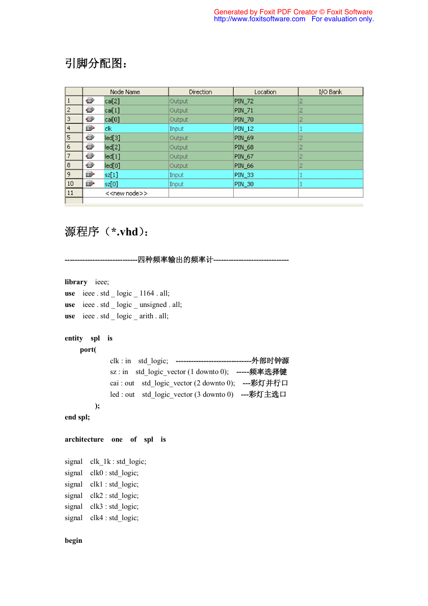
引脚分配图:
源程序(*.vhd):
-----------------------------四种频率输出的频率计------------------------------
library ieee;
use ieee . std _ logic _ 1164 . all;
use ieee . std _ logic _ unsigned . all;
use ieee . std _ logic _ arith . all;
entity spl is
end spl;
architecture one of spl is
signal clk_1k : std_logic;
signal clk0 : std_logic;
signal clk1 : std_logic;
signal clk2 : std_logic;
signal clk3 : std_logic;
signal clk4 : std_logic;
begin
clk : in std_logic; ------------------------------外部时钟源
sz : in std_logic_vector (1 downto 0); -----频率选择键
cai : out std_logic_vector (2 downto 0); ---彩灯并行口
led : out std_logic_vector (3 downto 0) ---彩灯主选口
port(
);
�
Generated by Foxit PDF Creator © Foxit Software
http://www.foxitsoftware.com For evaluation only.
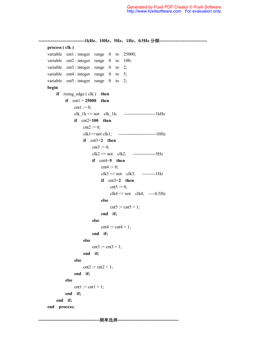
-------------------------------1kHz、10Hz、5Hz、1Hz、0.5Hz 分频--------------------------------
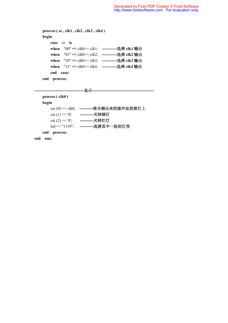
-----------------------------------------频率选择-----------------------------------------
process ( clk )
variable cnt1 : integer range 0 to 25000;
variable cnt2 : integer range 0 to 100;
variable cnt3 : integer range 0 to 2;
variable cnt4 : integer range 0 to 5;
variable cnt5 : integer range 0 to 2;
begin
if rising_edge ( clk ) then
if cnt1 = 25000 then
else
end if;
end if;
end process;
cnt3 := 0;
clk2 <= not clk2; ---------------5Hz
if cnt4=5 then
else
end if;
cnt5 := 0;
clk4 <= not clk4; ----0.5Hz
cnt1 := cnt1 + 1;
cnt3 := cnt3 + 1;
cnt1 := 0;
clk_1k <= not clk_1k; ---------------------1kHz
if cnt2=100 then
else
end if;
cnt2 := 0;
clk1<=not clk1; -------------------------10Hz
if cnt3=2 then
else
end if;
cnt4 := 0;
clk3 <= not clk3; ---------1Hz
if cnt5=2 then
else
end if;
cnt2 := cnt2 + 1;
cnt4 := cnt4 + 1;
cnt5 := cnt5 + 1;
�
Generated by Foxit PDF Creator © Foxit Software
http://www.foxitsoftware.com For evaluation only.
process ( sz , clk1 , clk2 , clk3 , clk4 )
begin
case sz is
when "00" => clk0<= clk1; -----------选择 clk1 输出
when "01" => clk0<= clk2; -----------选择 clk2 输出
when "10" => clk0<= clk3; -----------选择 clk3 输出
when "11" => clk0<= clk4; -----------选择 clk4 输出
end case;
end process;
-------------------------------------显示----------------------------------------------
end one;
process ( clk0 )
begin
end process;
cai (0) <= clk0; ----------将分频出来的脉冲加到黄灯上
cai (1) <= '0'; ----------灭掉绿灯
cai (2) <= '0'; ----------灭掉红灯
led <= "1110"; ----------选择其中一组的灯亮
�


 2023年江西萍乡中考道德与法治真题及答案.doc
 2012年重庆南川中考生物真题及答案.doc
 2013年江西师范大学地理学综合及文艺理论基础考研真题.doc
 2020年四川甘孜小升初语文真题及答案I卷.doc
 2020年注册岩土工程师专业基础考试真题及答案.doc
 2023-2024学年福建省厦门市九年级上学期数学月考试题及答案.doc
 2021-2022学年辽宁省沈阳市大东区九年级上学期语文期末试题及答案.doc
 2022-2023学年北京东城区初三第一学期物理期末试卷及答案.doc
 2018上半年江西教师资格初中地理学科知识与教学能力真题及答案.doc
 2012年河北国家公务员申论考试真题及答案-省级.doc
 2020-2021学年江苏省扬州市江都区邵樊片九年级上学期数学第一次质量检测试题及答案.doc
 2022下半年黑龙江教师资格证中学综合素质真题及答案.doc