WORLDWIDE
ENGINEERING
STANDARDS
GMLAN ENHANCED DIAGNOSTIC TEST MODE
SPECIFICATION
GMW 3110
STATUS:
SPECIFICATION
VERSION:
1.5
DATE: FEBRUARY 4TH 2004
File: GMW3110_V15.doc
Authors:
GMLAN Diagnostic Sub-Group
�
04-Feb-04
GMLAN Enhanced Diagnostic Test Mode Specification GMW 3110
Specification Version 1.5
WORLDWIDE
ENGINEERING
STANDARDS
THIS PAGE INTENTIONALLY LEFT BLANK
GMW3110 - GMLAN Enhanced Diagnostic Test Mode Specification - Version 1.5 - 2004-02-4.doc © February, 2004 General
Motors Corporation All Rights Reserved
Originating Department: North American Engineering Standards, Records And Documentation
Page 2 Of 325
�
04-Feb-04
GMLAN Enhanced Diagnostic Test Mode Specification GMW 3110
Specification Version 1.5
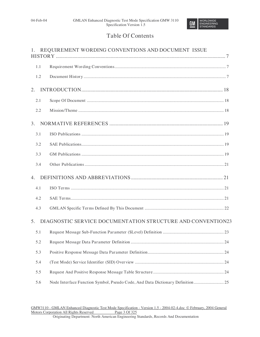
Table Of Contents
WORLDWIDE
ENGINEERING
STANDARDS
1. REQUIREMENT WORDING CONVENTIONS AND DOCUMENT ISSUE
HISTORY ..................................................................................................................................... 7
1.1
1.2
Requirement Wording Conventions........................................................................................................ 7
Document History ..................................................................................................................................... 7
2.
INTRODUCTION............................................................................................................... 18
2.1
Scope Of Document ................................................................................................................................ 18
2.2 Mission/Theme ........................................................................................................................................ 18
3. NORMATIVE REFERENCES ......................................................................................... 19
3.1
3.2
3.3
3.4
ISO Publications ..................................................................................................................................... 19
SAE Publications..................................................................................................................................... 19
GM Publications ..................................................................................................................................... 19
Other Publications .................................................................................................................................. 21
4. DEFINITIONS AND ABBREVIATIONS........................................................................ 21
4.1
4.2
4.3
ISO Terms ............................................................................................................................................... 21
SAE Terms............................................................................................................................................... 21
GMLAN Specific Terms Defined By This Document .......................................................................... 22
5. DIAGNOSTIC SERVICE DOCUMENTATION STRUCTURE AND CONVENTION23
5.1
5.2
5.3
5.4
5.5
5.6
Request Message Sub-Function Parameter ($Level) Definition ......................................................... 23
Request Message Data Parameter Definition....................................................................................... 24
Positive Response Message Data Parameter Definition....................................................................... 24
(Test Mode) Service Identifier (SID) Overview ................................................................................... 24
Request And Positive Response Message Table Structure.................................................................. 24
Node Interface Function Symbol, Pseudo Code, And Data Dictionary Definition............................ 25
GMW3110 - GMLAN Enhanced Diagnostic Test Mode Specification - Version 1.5 - 2004-02-4.doc © February, 2004 General
Motors Corporation All Rights Reserved
Originating Department: North American Engineering Standards, Records And Documentation
Page 3 Of 325
�
04-Feb-04
GMLAN Enhanced Diagnostic Test Mode Specification GMW 3110
Specification Version 1.5
WORLDWIDE
ENGINEERING
STANDARDS
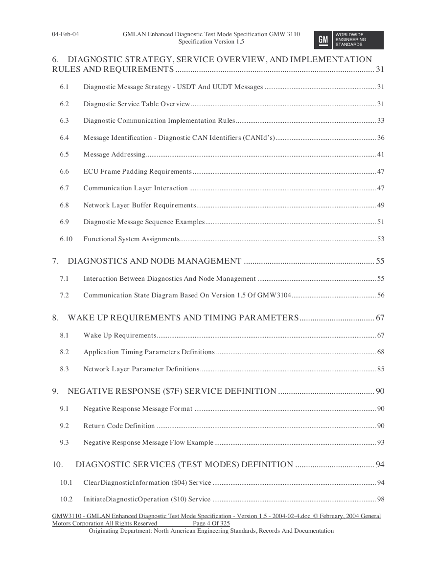
6. DIAGNOSTIC STRATEGY, SERVICE OVERVIEW, AND IMPLEMENTATION
RULES AND REQUIREMENTS ............................................................................................. 31
6.1
6.2
6.3
Diagnostic Message Strategy - USDT And UUDT Messages .............................................................. 31
Diagnostic Service Table Overview....................................................................................................... 31
Diagnostic Communication Implementation Rules.............................................................................. 33
6.4 Message Identification - Diagnostic CAN Identifiers (CANId’s)........................................................ 36
6.5 Message Addressing................................................................................................................................ 41
6.6
6.7
6.8
6.9
ECU Frame Padding Requirements...................................................................................................... 47
Communication Layer Interaction........................................................................................................ 47
Network Layer Buffer Requirements.................................................................................................... 49
Diagnostic Message Sequence Examples............................................................................................... 51
6.10
Functional System Assignments............................................................................................................. 53
7. DIAGNOSTICS AND NODE MANAGEMENT ............................................................. 55
7.1
7.2
Interaction Between Diagnostics And Node Management .................................................................. 55
Communication State Diagram Based On Version 1.5 Of GMW3104............................................... 56
8. WAKE UP REQUIREMENTS AND TIMING PARAMETERS................................... 67
8.1 Wake Up Requirements.......................................................................................................................... 67
8.2
8.3
Application Timing Parameters Definitions ......................................................................................... 68
Network Layer Parameter Definitions.................................................................................................. 85
9. NEGATIVE RESPONSE ($7F) SERVICE DEFINITION ............................................. 90
9.1
9.2
9.3
Negative Response Message Format ..................................................................................................... 90
Return Code Definition .......................................................................................................................... 90
Negative Response Message Flow Example.......................................................................................... 93
10. DIAGNOSTIC SERVICES (TEST MODES) DEFINITION ..................................... 94
10.1 ClearDiagnosticInformation ($04) Service ........................................................................................... 94
10.2
InitiateDiagnosticOperation ($10) Service ........................................................................................... 98
GMW3110 - GMLAN Enhanced Diagnostic Test Mode Specification - Version 1.5 - 2004-02-4.doc © February, 2004 General
Motors Corporation All Rights Reserved
Originating Department: North American Engineering Standards, Records And Documentation
Page 4 Of 325
�
04-Feb-04
GMLAN Enhanced Diagnostic Test Mode Specification GMW 3110
Specification Version 1.5
WORLDWIDE
ENGINEERING
STANDARDS
10.3 ReadFailureRecordData ($12) Service ............................................................................................... 104
10.4 ReadDataByIdentifier ($1A) Service................................................................................................... 114
10.5 ReturnToNormalMode ($20) Service.................................................................................................. 118
10.6 ReadDataByParameterIdentifier ($22 ) Service ................................................................................ 125
10.7 ReadMemoryByAddress ($23) Service ............................................................................................... 136
10.8
SecurityAccess ($27) Service................................................................................................................ 143
10.9 DisableNormalCommunication ($28) Service..................................................................................... 153
10.10
DynamicallyDefineMessage ($2C) Service ..................................................................................... 157
10.11
DefinePIDByAddress ($2D) Service................................................................................................ 164
10.12
RequestDownload ($34) Service...................................................................................................... 171
10.13
TransferData ($36) Service.............................................................................................................. 177
10.14 WriteDataByIdentifier ($3B) Service ............................................................................................. 185
10.15
TesterPresent ($3E) Service............................................................................................................. 189
10.16
ReportProgrammedState ($A2) Service ......................................................................................... 193
10.17
ProgrammingMode ($A5) Service................................................................................................... 199
10.18
ReadDiagnosticInformation ($A9) Service..................................................................................... 208
10.19
ReadDataByPacketIdentifier ($AA) Service.................................................................................. 224
10.20
DeviceControl ($AE) Service........................................................................................................... 247
11. ECU PROGRAMMING REQUIREMENTS AND PROCESS ................................ 256
11.1 ECU Programming General Requirements / Information ................................................................ 256
11.2 Requirements For All ECU’s To Support Programming.................................................................. 259
11.3 Requirements For SPS Programmable ECU’s To Support Programming...................................... 260
11.4 ECU Programming Process ................................................................................................................. 282
11.5 ECU Programming Message Flow Example....................................................................................... 291
12. APPENDICES ............................................................................................................... 297
12.1 Appendix A - Device Control Limits Exceeded Return Code Definition ......................................... 297
GMW3110 - GMLAN Enhanced Diagnostic Test Mode Specification - Version 1.5 - 2004-02-4.doc © February, 2004 General
Motors Corporation All Rights Reserved
Originating Department: North American Engineering Standards, Records And Documentation
Page 5 Of 325
�
04-Feb-04
GMLAN Enhanced Diagnostic Test Mode Specification GMW 3110
Specification Version 1.5
WORLDWIDE
ENGINEERING
STANDARDS
12.2 Appendix B - Corporate Common CPID Definitions ........................................................................ 300
12.3 Appendix C - Corporate Standard Data Identifiers (DID) ............................................................... 302
12.4 Appendix D - Diagnostic Addresses..................................................................................................... 315
12.5 Appendix E - DTC Status Byte & Failure Type Byte Definitions..................................................... 316
GMW3110 - GMLAN Enhanced Diagnostic Test Mode Specification - Version 1.5 - 2004-02-4.doc © February, 2004 General
Motors Corporation All Rights Reserved
Originating Department: North American Engineering Standards, Records And Documentation
Page 6 Of 325
�
04-Feb-04
GMLAN Enhanced Diagnostic Test Mode Specification GMW 3110
Specification Version 1.5
WORLDWIDE
ENGINEERING
STANDARDS
1. Requirement Wording Conventions And Document Issue History
1.1 Requirement Wording Conventions
Within this document the following conventions are applied when describing specific compliance
requirements:
The word “Shall” is used in the following ways:
1. To state a binding requirement on the GMLAN network, or the nodes which comprise the network,
which is verifiable by external manipulation and/or observation of a node or the network.
2. To state a binding requirement upon a nodes requirements document that is verifiable through a review
of the document.
The word “Must” is used to state a binding requirement upon nodes on the network which have a
corresponding node requirements document. These requirements will be verified as part of the
component verification.
The word “Should” denotes a preference or desired conformance.
1.2 Document History
The following table contains the revision history for this specification:
Issue#
Date
Revision History
0.1
0.2
0.2
0.2
0.2
0.2
0.2
0.3
0.3
0.3
0.3
0.3
0.3
0.3
0.3
02July98
05Oct98
05Oct98
05Oct98
Initial Draft
Reformatted tables and styles used within the document for consistency.
Corrected error in CAN Identifiers section to show the correct range of reserved CAN Id’s
for physical diagnostic request messages.
The following modes have been modified from the initial draft: $04, $10, $12, $27, $28,
$3E, $84, $AE.
05Oct98 Modes $10, $20, $28, and $AE were modified along with the global data dictionary table
05Oct98
to reflect a single flag for disabling DTC’s during enhanced diagnostics.
Each Appendix was separated into a separate sub-document and revisions were made to
the diagnostic communication matrix appendix.
Added a chapter to document Flash Programming Process.
05Oct98
20Nov98 Deleted the NetworkConfiguration service $84 and created DIDs to replace the
functionality.
20Nov98 Modified All Appendices to reflect changes from October 1998 Co-Location.
20Nov98
Accepted revisions to all services from October Co-Location and changed all the CANIds
to match the latest reserved ranges. Changed all of the “S” values in the convention (Cvt)
columns of the tables to “M”. Changed all consecutive frames after the initial flow control
frame to have a PCI value of $21 (per ISO 15765-2).
20Nov98 Reordered the initial sections of the document prior to the test services for better
readability.
20Nov98 Made several modifications to the $AA service description, pseudo code, data dictionary,
and allowed negative response codes.
20Nov98 Made several changes to the chapter describing the module programming procedures.
The global pseudo code table was modified to add a column for power up initialization
20Nov98
values. There were also changes to some of the global variables in the table.
There were changes to the negative response code section to not have a negative
response code $11 sent if the request was functionally addressed. Response code $33
was eliminated.
20Nov98
GMW3110 - GMLAN Enhanced Diagnostic Test Mode Specification - Version 1.5 - 2004-02-4.doc © February, 2004 General
Motors Corporation All Rights Reserved
Originating Department: North American Engineering Standards, Records And Documentation
Page 7 Of 325
�
04-Feb-04
GMLAN Enhanced Diagnostic Test Mode Specification GMW 3110
Specification Version 1.5
WORLDWIDE
ENGINEERING
STANDARDS
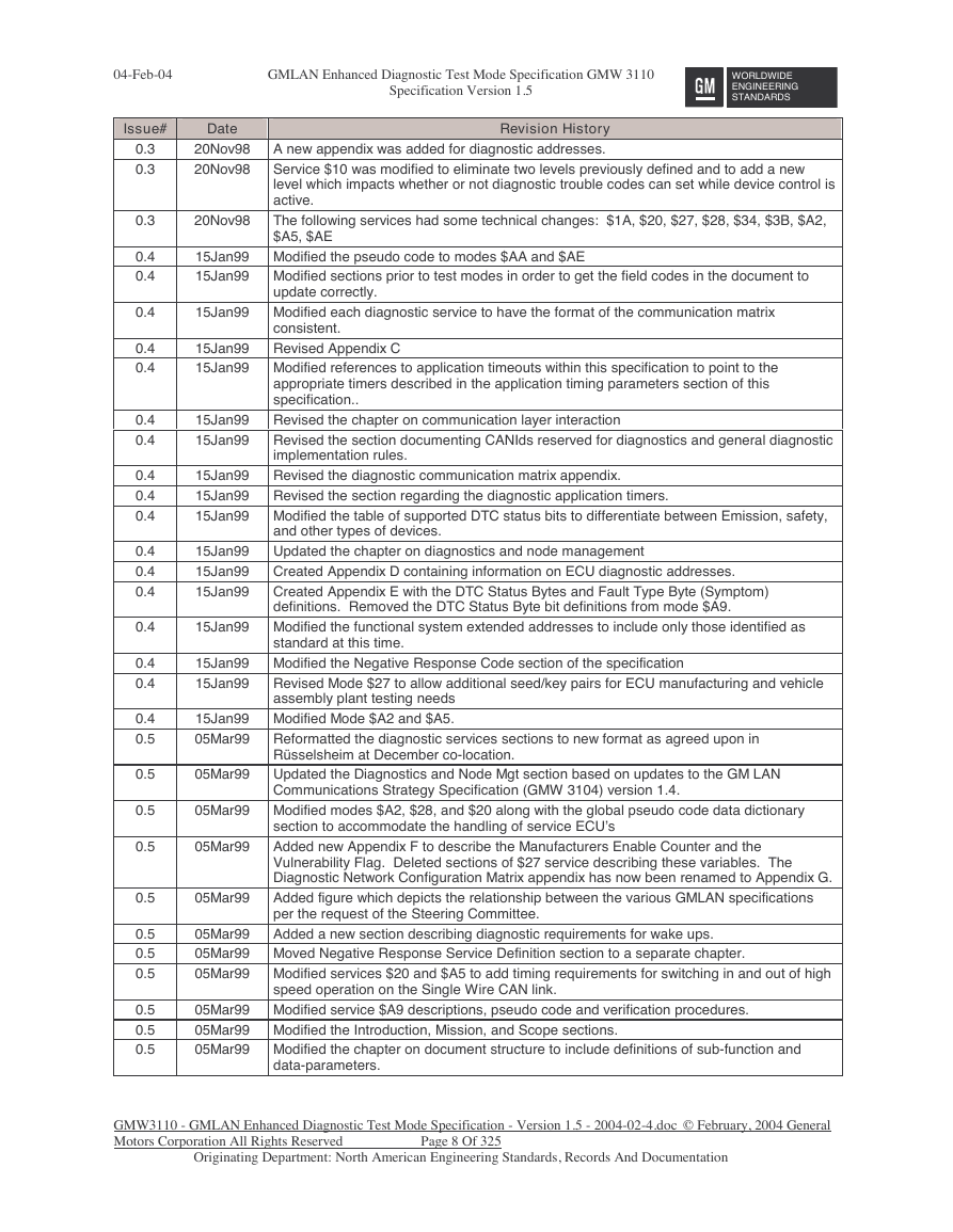
Issue#
Date
0.3
0.3
0.3
0.4
0.4
0.4
0.4
0.4
0.4
0.4
0.4
0.4
0.4
0.4
0.4
0.4
0.4
0.4
0.4
0.4
0.5
0.5
0.5
0.5
0.5
0.5
0.5
0.5
0.5
0.5
0.5
20Nov98
20Nov98
20Nov98
Revision History
A new appendix was added for diagnostic addresses.
Service $10 was modified to eliminate two levels previously defined and to add a new
level which impacts whether or not diagnostic trouble codes can set while device control is
active.
The following services had some technical changes: $1A, $20, $27, $28, $34, $3B, $A2,
$A5, $AE
15Jan99 Modified the pseudo code to modes $AA and $AE
15Jan99 Modified sections prior to test modes in order to get the field codes in the document to
update correctly.
15Jan99 Modified each diagnostic service to have the format of the communication matrix
consistent.
15Jan99 Revised Appendix C
15Jan99 Modified references to application timeouts within this specification to point to the
appropriate timers described in the application timing parameters section of this
specification..
15Jan99 Revised the chapter on communication layer interaction
15Jan99 Revised the section documenting CANIds reserved for diagnostics and general diagnostic
implementation rules.
15Jan99 Revised the diagnostic communication matrix appendix.
15Jan99 Revised the section regarding the diagnostic application timers.
15Jan99 Modified the table of supported DTC status bits to differentiate between Emission, safety,
and other types of devices.
15Jan99 Updated the chapter on diagnostics and node management
15Jan99 Created Appendix D containing information on ECU diagnostic addresses.
15Jan99 Created Appendix E with the DTC Status Bytes and Fault Type Byte (Symptom)
definitions. Removed the DTC Status Byte bit definitions from mode $A9.
15Jan99 Modified the functional system extended addresses to include only those identified as
standard at this time.
15Jan99 Modified the Negative Response Code section of the specification
15Jan99 Revised Mode $27 to allow additional seed/key pairs for ECU manufacturing and vehicle
assembly plant testing needs
15Jan99 Modified Mode $A2 and $A5.
05Mar99 Reformatted the diagnostic services sections to new format as agreed upon in
Rüsselsheim at December co-location.
05Mar99 Updated the Diagnostics and Node Mgt section based on updates to the GM LAN
Communications Strategy Specification (GMW 3104) version 1.4.
05Mar99 Modified modes $A2, $28, and $20 along with the global pseudo code data dictionary
05Mar99
05Mar99
section to accommodate the handling of service ECU’s
Added new Appendix F to describe the Manufacturers Enable Counter and the
Vulnerability Flag. Deleted sections of $27 service describing these variables. The
Diagnostic Network Configuration Matrix appendix has now been renamed to Appendix G.
Added figure which depicts the relationship between the various GMLAN specifications
per the request of the Steering Committee.
Added a new section describing diagnostic requirements for wake ups.
05Mar99
05Mar99 Moved Negative Response Service Definition section to a separate chapter.
05Mar99 Modified services $20 and $A5 to add timing requirements for switching in and out of high
speed operation on the Single Wire CAN link.
05Mar99 Modified service $A9 descriptions, pseudo code and verification procedures.
05Mar99 Modified the Introduction, Mission, and Scope sections.
05Mar99 Modified the chapter on document structure to include definitions of sub-function and
data-parameters.
GMW3110 - GMLAN Enhanced Diagnostic Test Mode Specification - Version 1.5 - 2004-02-4.doc © February, 2004 General
Motors Corporation All Rights Reserved
Originating Department: North American Engineering Standards, Records And Documentation
Page 8 Of 325
�





 2023年江西萍乡中考道德与法治真题及答案.doc
 2012年重庆南川中考生物真题及答案.doc
 2013年江西师范大学地理学综合及文艺理论基础考研真题.doc
 2020年四川甘孜小升初语文真题及答案I卷.doc
 2020年注册岩土工程师专业基础考试真题及答案.doc
 2023-2024学年福建省厦门市九年级上学期数学月考试题及答案.doc
 2021-2022学年辽宁省沈阳市大东区九年级上学期语文期末试题及答案.doc
 2022-2023学年北京东城区初三第一学期物理期末试卷及答案.doc
 2018上半年江西教师资格初中地理学科知识与教学能力真题及答案.doc
 2012年河北国家公务员申论考试真题及答案-省级.doc
 2020-2021学年江苏省扬州市江都区邵樊片九年级上学期数学第一次质量检测试题及答案.doc
 2022下半年黑龙江教师资格证中学综合素质真题及答案.doc