V1.2
PX30
Hardware Design Guide
Version:
:
::
V1.2
Author:
:
::
Auditor:
:
::
Approver:
:
::
Date:
:
::
05.15.2019
1
�
V1.2
Warranty Disclaimer
The products, services or features you have purchased from Fuzhou Rockchip Electronics Co.,
Ltd shall be binding upon terms and conditions of mutual business contract, all or part of
products, services or features may be exclusive of your purchase or range of application.
Unless otherwise agreed on contract, no expressed or implied copyright licenses have been
granted hereunder this document.
Fuzhou Rockchip Electronics Co., Ltd reserves the right to make changes in its products or
product specifications with the intent to improve function or design at any time. Unless
otherwise agreed, this document is provided as user's manual only, no expressed or implied
copyright licenses have been granted hereunder statement, information and suggestion of
this document.
Trademarks
Rockchip and RockchipTM logo and the name of Fuzhou Rockchip Electronics Co., Ltd’ s
products are trademarks of Fuzhou Rockchip Electronics Co., Ltd. and are exclusively owned
by Fuzhou Rockchip Electronics Co., Ltd.
References to other companies and their products use trademarks owned by the respective
companies and are for reference purpose only.
。
Copyright © Fuzhou Rockchip Electronics Co., Ltd. 2015
All rights reserved. No part of this publication may be reproduced, stored in a retrieval system,
or transmitted in any form or by any means, electric or mechanical, by photocopying,
recording, or otherwise, without the prior written consent of Fuzhou Rockchip Electronics Co.,
Ltd.
Fuzhou Rockchip Electronics Co., Ltd
Address: No.18 Building, A District, No.89 Software Boulevard,
FuZhou, FuJian, PRC
Website: www.rock-chips.com
Tel: +86-591-83991906
Fax: +86-591-83951833
Mail: www.rock-chips.com
2
�
V1.2
Preface
Overview
This document mainly introduces the key points of hardware design for PX30, aiming at
helping customers to shorten product design period, improve stability and reduce bugs.
Please follow this guide strictly for the hardware design, and use the relative core board
released by RK. If need to change in special cases, please get confirmation from RK engineer
first.
Chipset model
The chipset model described in this document is PX30
Relevant product versions are shown as below:
Product Name
PX30 MINI EVB
Product Version
Applicable object
This document is mainly suitable for the following engineers:
1. Hardware development & PCB layout engineers
2. Field application engineers
3. Test engineers
3
�
V1.2
Revision history
This revision history recorded description of each version, and any updates of previous
versions are included in the latest one.
Revision Date Version No.
Author
Revision Description
2018-09
V1.0
Hardware Group
Initial Release
2019-01
V1.1
Hardware Group
Initial Release
2019-05
V1.2
Hardware Group
Initial Release
4
�
V1.2
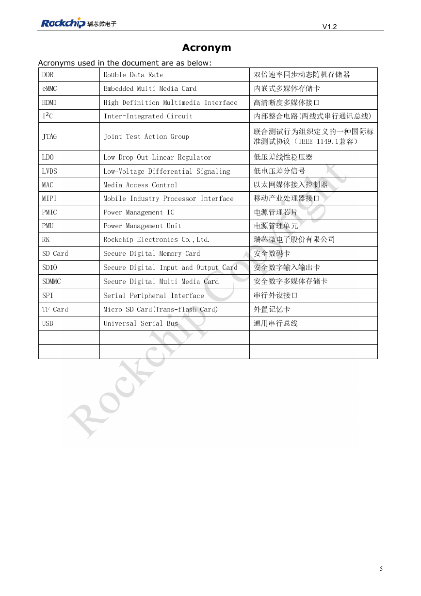
Acronyms used in the document are as below:
Acronym
DDR
Double Data Rate
双倍速率同步动态随机存储器
eMMC
Embedded Multi Media Card
内嵌式多媒体存储卡
HDMI
High Definition Multimedia Interface 高清晰度多媒体接口
2
I
C
Inter-Integrated Circuit
内部整合电路(两线式串行通讯总线)
JTAG
Joint Test Action Group
联合测试行为组织定义的一种国际标
准测试协议(IEEE 1149.1兼容)
LDO
Low Drop Out Linear Regulator
低压差线性稳压器
LVDS
Low-Voltage Differential Signaling
低电压差分信号
MAC
Media Access Control
以太网媒体接入控制器
MIPI
Mobile Industry Processor Interface
移动产业处理器接口
PMIC
Power Management IC
电源管理芯片
PMU
Power Management Unit
电源管理单元
RK
Rockchip Electronics Co.,Ltd.
瑞芯微电子股份有限公司
SD Card
Secure Digital Memory Card
安全数码卡
SDIO
Secure Digital Input and Output Card 安全数字输入输出卡
SDMMC
Secure Digital Multi Media Card
安全数字多媒体存储卡
SPI
Serial Peripheral Interface
串行外设接口
TF Card
Micro SD Card(Trans-flash Card)
外置记忆卡
USB
Universal Serial Bus
通用串行总线
5
�
V1.2
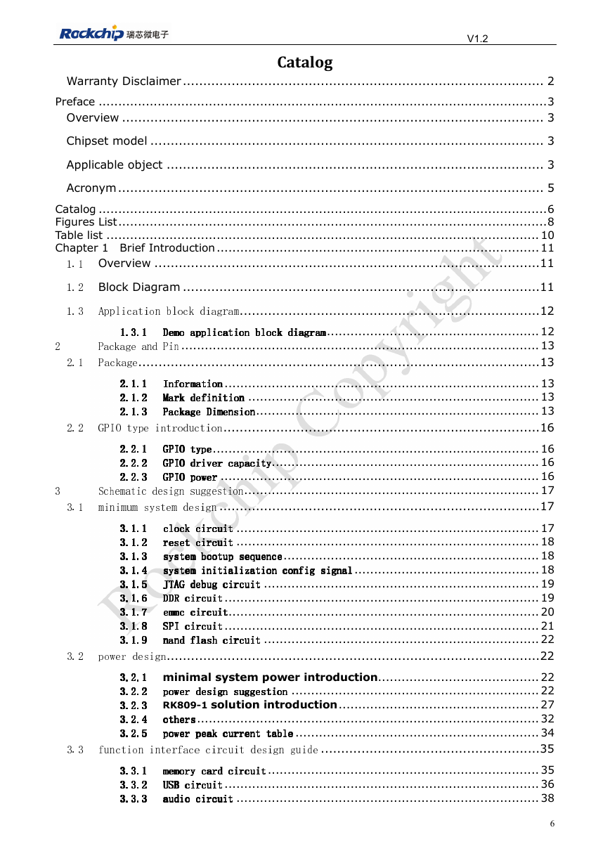
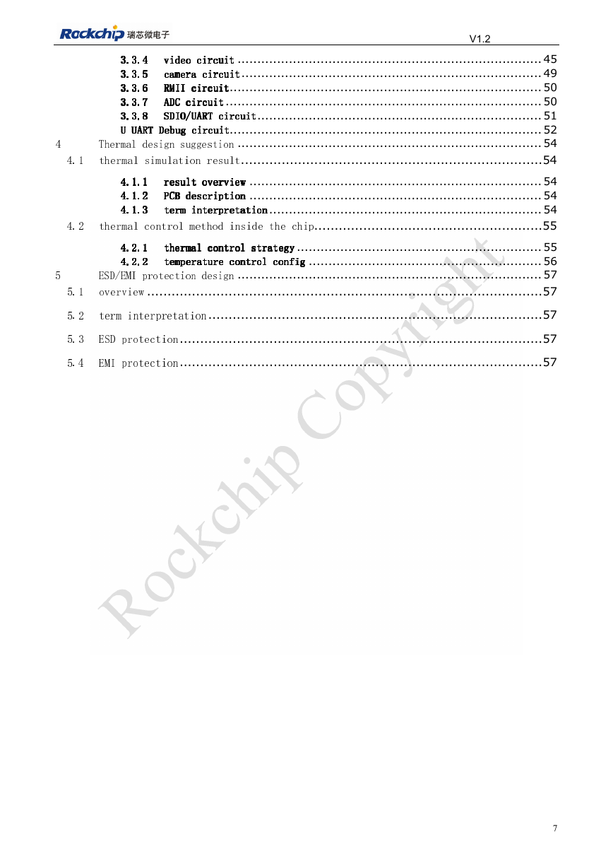
Catalog
Warranty Disclaimer ......................................................................................... 2
Preface .................................................................................................................. 3
Overview ........................................................................................................ 3
Chipset model ................................................................................................. 3
Applicable object ............................................................................................. 3
Acronym ......................................................................................................... 5
Catalog .................................................................................................................. 6
Figures List ............................................................................................................. 8
Table list .............................................................................................................. 10
Chapter 1 Brief Introduction .................................................................................. 11
1.1 Overview ............................................................................................... 11
1.2 Block Diagram ........................................................................................ 11
1.3
Application block diagram .......................................................................... 12
2
1.3.1
1.3.1
1.3.1
1.3.1
Demo application block diagram ...................................................... 12
Package and Pin ........................................................................................... 13
Demo application block diagram
Demo application block diagram
Demo application block diagram
2.1
Package ................................................................................................... 13
2.1.2
2.1.2
2.1.2
2.1.1
2.1.1
2.1.1
Information
Information
Information
2.1.1
2.1.2
Information ................................................................................ 13
Mark definition .......................................................................... 13
Package Dimension ........................................................................ 13
GPIO type introduction .............................................................................. 16
2.1.3
Package Dimension
Package Dimension
Package Dimension
Mark definition
Mark definition
Mark definition
2.1.3
2.1.3
2.1.3
2.2.2
2.2.2
2.2.2
2.2.1
2.2.1
2.2.1
GPIO type
GPIO type
GPIO type
GPIO driver capacity
GPIO driver capacity
GPIO driver capacity
2.2.1
2.2.2
GPIO type ................................................................................... 16
GPIO driver capacity .................................................................... 16
GPIO power ................................................................................. 16
Schematic design suggestion ........................................................................... 17
minimum system design ............................................................................... 17
2.2.3
GPIO power
GPIO power
GPIO power
2.2.3
2.2.3
2.2.3
2.2
3
3.1
3.1.1
3.1.1
3.1.1
3.1.1
.1.2
3.1.2
3
33
.1.2.1.2
3.1.3
3.1.3
3.1.3
3.1.3
3.1.4
3.1.4
3.1.4
3.1.4
3.1.5
3.1.5
3.1.5
3.1.5
3.1.6
3.1.6
3.1.6
3.1.6
3.1.7
3.1.7
3.1.7
3.1.7
3.1.8
3.1.8
3.1.8
3.1.8
3.1.9
3.1.9
3.1.9
3.1.9
reset circuit
reset circuit
reset circuit
clock circuit
clock circuit
clock circuit
system bootup sequence
system bootup sequence
system bootup sequence
system initialization config signal
system initialization config signal
system initialization config signal
clock circuit ............................................................................. 17
reset circuit ............................................................................. 18
system bootup sequence ................................................................. 18
system initialization config signal ............................................... 18
JTAG debug circuit ...................................................................... 19
DDR circuit ................................................................................ 19
emmc circuit ............................................................................... 20
SPI circuit ................................................................................ 21
nand flash circuit ...................................................................... 22
JTAG debug circuit
JTAG debug circuit
JTAG debug circuit
nand flash circuit
nand flash circuit
nand flash circuit
emmc circuit
emmc circuit
emmc circuit
DDR circuit
DDR circuit
DDR circuit
SPI circuit
SPI circuit
SPI circuit
3.2
power design ............................................................................................ 22
3.2.3
3.2.3
3.2.3
3.2.2
3.2.2
3.2.2
3.2.1
3.2.1
3.2.1
power design suggestion
power design suggestion
power design suggestion
3.2.1 minimal system power introduction......................................... 22
power design suggestion ............................................................... 22
3.2.2
3.2.3 RK809-1 solution introduction ................................................... 27
others ....................................................................................... 32
3.2.4
power peak current table .............................................................. 34
function interface circuit design guide ...................................................... 35
3.2.5
power peak current table
power peak current table
power peak current table
others
others
others
3.2.5
3.2.5
3.2.5
3.2.4
3.2.4
3.2.4
3.3.1
3.3.1
3.3.1
3.3.1
3.3.2
3.3.2
3.3.2
3.3.2
3.3.3
3.3.3
3.3.3
3.3.3
memory card circuit
memory card circuit
memory card circuit
memory card circuit ..................................................................... 35
USB circuit ................................................................................ 36
audio circuit ............................................................................. 38
audio circuit
audio circuit
audio circuit
USB circuit
USB circuit
USB circuit
6
3.3
�
V1.2
3.3.6
3.3.6
3.3.6
3.3.5
3.3.5
3.3.5
3.3.4
3.3.4
3.3.4
RMII circuit
video circuit
video circuit
video circuit
camera circuit
camera circuit
camera circuit
3.3.6
3.3.4
3.3.5
video circuit ............................................................................. 45
camera circuit ............................................................................ 49
RMII circuit ............................................................................... 50
ADC circuit ................................................................................ 50
SDIO/UART circuit ........................................................................ 51
U UART Debug circuit............................................................................... 52
Thermal design suggestion ............................................................................. 54
3.3.7
3.3.8
U UART Debug circuit
U UART Debug circuit
U UART Debug circuit
SDIO/UART circuit
SDIO/UART circuit
SDIO/UART circuit
RMII circuit
RMII circuit
ADC circuit
ADC circuit
ADC circuit
3.3.7
3.3.7
3.3.7
3.3.8
3.3.8
3.3.8
4.1
thermal simulation result .......................................................................... 54
4.1.2
4.1.2
4.1.2
4.1.1
4.1.1
4.1.1
result overview
result overview
result overview
4.1.1
4.1.2
result overview .......................................................................... 54
PCB description .......................................................................... 54
retation ..................................................................... 54
thermal control method inside the chip ........................................................ 55
4.1.3
term interpretation
PCB description
PCB description
PCB description
term interp
term interp
term interp
retation
retation
4.1.3
4.1.3
4.1.3
4.2
4.2.1
4.2.1
4.2.1
thermal control strategy
4.2.1
thermal control strategy .............................................................. 55
temperature control config ........................................................... 56
ESD/EMI protection design ............................................................................. 57
4.2.2
temperature control config
temperature control config
temperature control config
thermal control strategy
thermal control strategy
4.2.2
4.2.2
4.2.2
5.1
overview ................................................................................................. 57
5.2
term interpretation .................................................................................. 57
5.3
ESD protection ......................................................................................... 57
5.4
EMI protection ......................................................................................... 57
7
4
5
�
V1.2
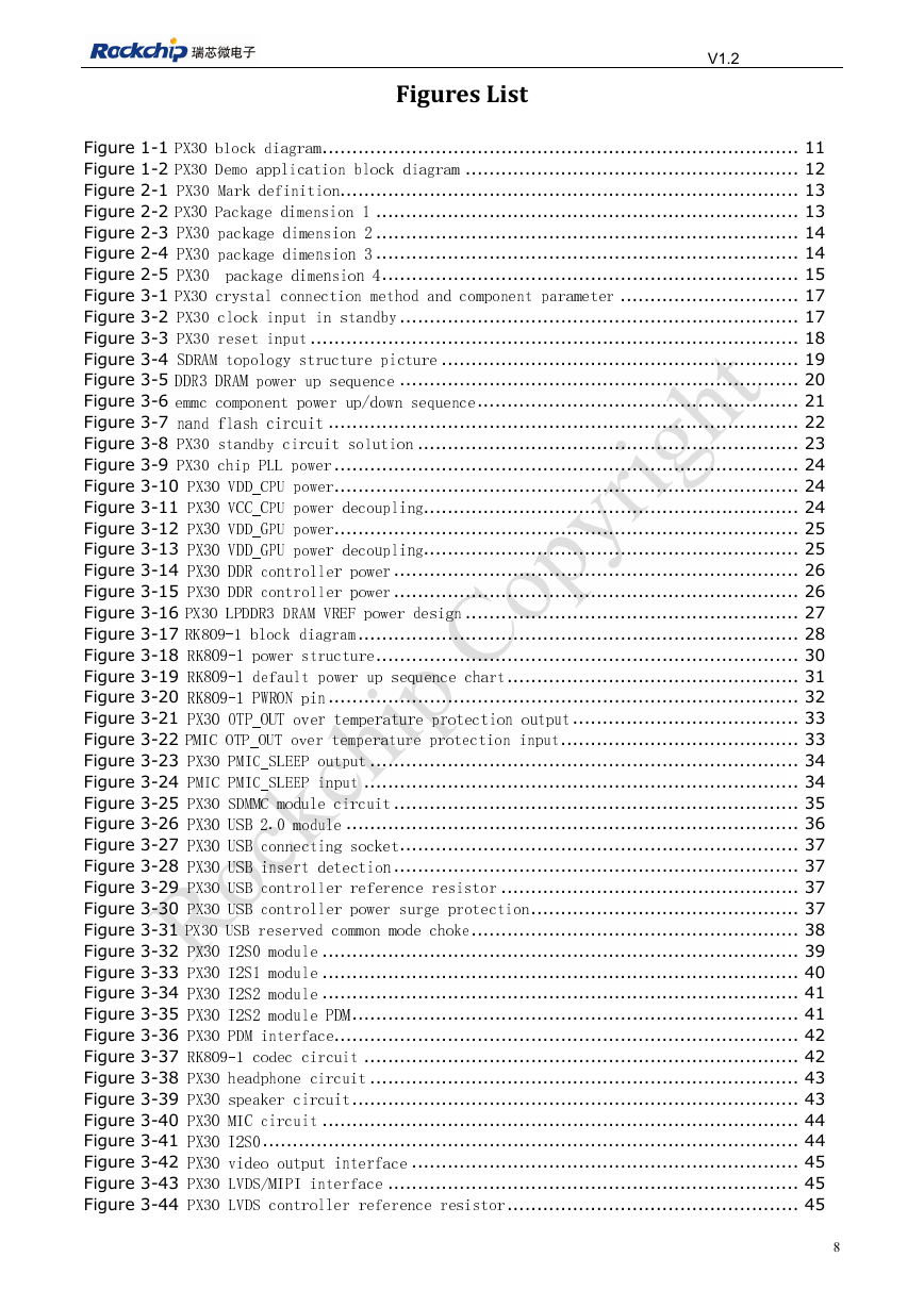
Figures List
Figure 1-1 PX30 block diagram ................................................................................ 11
Figure 1-2 PX30
Demo application block diagram ........................................................ 12
Figure 2-1 PX30 Mark definition ............................................................................. 13
Figure 2-2 PX30 Package dimension 1 ....................................................................... 13
Figure 2-3 PX30 package dimension 2 ....................................................................... 14
Figure 2-4 PX30 package dimension 3 ....................................................................... 14
Figure 2-5 PX30 package dimension 4 ...................................................................... 15
Figure 3-1 PX30 crystal connection method and component parameter .............................. 17
Figure 3-2 PX30 clock input in standby ................................................................... 17
Figure 3-3 PX30 reset input .................................................................................. 18
Figure 3-4 SDRAM topology structure picture ............................................................ 19
Figure 3-5 DDR3 DRAM power up sequence ................................................................... 20
Figure 3-6 emmc component power up/down sequence ...................................................... 21
Figure 3-7 nand flash circuit ............................................................................... 22
Figure 3-8 PX30 standby circuit solution ................................................................ 23
Figure 3-9 PX30 chip PLL power .............................................................................. 24
Figure 3-10 PX30 VDD_CPU power .............................................................................. 24
Figure 3-11 PX30 VCC_CPU power decoupling............................................................... 24
Figure 3-12 PX30 VDD_GPU power .............................................................................. 25
Figure 3-13 PX30 VDD_GPU power decoupling............................................................... 25
Figure 3-14 PX30 DDR controller power .................................................................... 26
Figure 3-15 PX30 DDR controller power .................................................................... 26
Figure 3-16 PX30 LPDDR3 DRAM VREF power design ........................................................ 27
Figure 3-17 RK809-1 block diagram .......................................................................... 28
Figure 3-18 RK809-1 power structure ....................................................................... 30
Figure 3-19 RK809-1 default power up sequence chart ................................................. 31
Figure 3-20 RK809-1 PWRON pin ............................................................................... 32
Figure 3-21 PX30 OTP_OUT over temperature protection output ...................................... 33
Figure 3-22 PMIC OTP_OUT over temperature protection input ........................................ 33
Figure 3-23 PX30 PMIC_SLEEP output ........................................................................ 34
Figure 3-24 PMIC PMIC_SLEEP input ......................................................................... 34
Figure 3-25 PX30 SDMMC module circuit .................................................................... 35
Figure 3-26 PX30 USB 2.0 module ............................................................................ 36
Figure 3-27 PX30 USB connecting socket ................................................................... 37
Figure 3-28 PX30 USB insert detection .................................................................... 37
Figure 3-29 PX30 USB controller reference resistor .................................................. 37
Figure 3-30 PX30 USB controller power surge protection ............................................. 37
Figure 3-31 PX30 USB reserved common mode choke ....................................................... 38
Figure 3-32 PX30 I2S0 module ................................................................................ 39
Figure 3-33 PX30 I2S1 module ................................................................................ 40
Figure 3-34 PX30 I2S2 module ................................................................................ 41
Figure 3-35 PX30 I2S2 module PDM ........................................................................... 41
Figure 3-36 PX30 PDM interface .............................................................................. 42
Figure 3-37 RK809-1 codec circuit ......................................................................... 42
Figure 3-38 PX30 headphone circuit ........................................................................ 43
Figure 3-39 PX30 speaker circuit ........................................................................... 43
Figure 3-40 PX30 MIC circuit ................................................................................ 44
Figure 3-41 PX30 I2S0 .......................................................................................... 44
Figure 3-42 PX30 video output interface ................................................................. 45
Figure 3-43 PX30 LVDS/MIPI interface ..................................................................... 45
Figure 3-44 PX30 LVDS controller reference resistor ................................................. 45
8
�


 2023年江西萍乡中考道德与法治真题及答案.doc
 2012年重庆南川中考生物真题及答案.doc
 2013年江西师范大学地理学综合及文艺理论基础考研真题.doc
 2020年四川甘孜小升初语文真题及答案I卷.doc
 2020年注册岩土工程师专业基础考试真题及答案.doc
 2023-2024学年福建省厦门市九年级上学期数学月考试题及答案.doc
 2021-2022学年辽宁省沈阳市大东区九年级上学期语文期末试题及答案.doc
 2022-2023学年北京东城区初三第一学期物理期末试卷及答案.doc
 2018上半年江西教师资格初中地理学科知识与教学能力真题及答案.doc
 2012年河北国家公务员申论考试真题及答案-省级.doc
 2020-2021学年江苏省扬州市江都区邵樊片九年级上学期数学第一次质量检测试题及答案.doc
 2022下半年黑龙江教师资格证中学综合素质真题及答案.doc