logo资料库

PCI Express Specification 1.0.pdf

第1页 / 共422页
第2页 / 共422页
第3页 / 共422页
第4页 / 共422页
第5页 / 共422页
第6页 / 共422页
第7页 / 共422页
第8页 / 共422页
资料共422页,剩余部分请下载后查看
PCI Express Base Specification, Rev. 1.0
Objective of the Specification
Document Organization
Documentation Conventions
Capitalization
Numbers and Number Bases
Implementation Notes
Terms and Acronyms
Reference Documents
1. Introduction
1.1. A Third Generation I/O Interconnect
1.2. PCI Express Link
1.3. PCI Express Fabric Topology
1.3.1. Root Complex
1.3.2. Endpoints
1.3.2.1. Legacy Endpoint Rules
1.3.2.2. PCI Express Endpoint Rules
1.3.3. Switch
1.3.4. PCI Express-PCI Bridge
1.4. PCI Express Fabric Topology Configuration
1.5. PCI Express Layering Overview
1.5.1. Transaction Layer
1.5.2. Data Link Layer
1.5.3. Physical Layer
1.5.4. Layer Functions and Services
1.5.4.1. Transaction Layer Services
1.5.4.2. Data Link Layer Services
1.5.4.3. Physical Layer Services
1.5.4.4. Inter-Layer Interfaces
1.5.4.4.1. Transaction/Data Link Interface
1.5.4.4.2. Data Link/Physical Interface
1.6. Advanced Peer-to-Peer Communication Overview
2. Transaction Layer Specification
2.1. Transaction Layer Overview
2.1.1. Address Spaces, Transaction Types, and Usage
2.1.1.1. Memory Transactions
2.1.1.2. I/O Transactions
2.1.1.3. Configuration Transactions
2.1.1.4. Message Transactions
2.1.2. Packet Format Overview
2.2. Transaction Layer Protocol - Packet Definition
2.2.1. Common Packet Header Fields
2.2.2. TLPs with Data Payloads - Rules
2.2.3. TLP Digest Rules
2.2.4. Routing and Addressing Rules
2.2.4.1. Address Based Routing Rules
2.2.4.2. ID Based Routing Rules
2.2.5. First/Last DW Byte Enable Rules
2.2.6. Transaction Descriptor
2.2.6.1. Overview
2.2.6.2. Transaction Descriptor – Transaction ID Field
2.2.6.3. Transaction Descriptor – Attributes Field
2.2.6.4. Relaxed Ordering Attribute
2.2.6.5. No Snoop Attribute
2.2.6.6. Transaction Descriptor – Traffic Class Field
2.2.7. Memory, I/O, and Configuration Request Rules
2.2.8. Message Request Rules
2.2.8.1. Baseline Message Group
2.2.8.1.1. INTx Interrupt Signaling - Rules
2.2.8.1.2. Power Management Messages
2.2.8.1.3. Error Signaling Messages
2.2.8.1.4. Locked Transactions Support
2.2.8.1.5. Slot Power Limit Support
2.2.8.1.6. Vendor_Defined Messages
2.2.8.1.7. Hot Plug Signaling Messages
2.2.8.2. Advanced Switching Support Message Group
2.2.9. Completion Rules
2.3. Handling of Received TLPs
2.3.1. Request Handling Rules
2.3.1.1. Data Return for Read Requests
2.3.2. Completion Handling Rules
2.4. Transaction Ordering
2.5. Virtual Channel (VC) Mechanism
2.5.1. Virtual Channel Identification (VC ID)
2.5.2. TC to VC Mapping
2.5.3. VC and TC Rules
2.6. Ordering and Receive Buffer Flow Control
2.6.1. Flow Control Rules
2.6.1.1. FC Information Tracked by Transmitter
2.6.1.2. FC Information Tracked by Receiver
2.7. Data Integrity
2.7.1. ECRC Rules
2.7.2. Error Forwarding
2.7.2.1. Error Forwarding Usage Model
2.7.2.2. Rules For Use of Data Poisoning
2.8. Completion Timeout Mechanism
2.9. Link Status Dependencies
2.9.1. Transaction Layer Behavior in DL_Down Status
2.9.2. Transaction Layer Behavior in DL_Up Status
3. Data Link Layer Specification
3.1. Data Link Layer Overview
3.2. Data Link Control and Management State Machine
3.2.1. Data Link Control and Management State Machine Rules
3.3. Flow Control Initialization Protocol
3.3.1. Flow Control Initialization State Machine Rules
3.4. Data Link Layer Packets (DLLPs)
3.4.1. Data Link Layer Packet Rules
3.5. Data Integrity
3.5.1. Introduction
3.5.2. LCRC, Sequence Number, and Retry Management (TLP Transmitter)
3.5.2.1. LCRC and Sequence Number Rules (TLP
3.5.3. LCRC and Sequence Number (TLP Receiver)
3.5.3.1. LCRC and Sequence Number Rules (TLP Receiver)
4. Physical Layer Specification
4.1. Introduction
4.2. Logical Sub-block
4.2.1. Symbol Encoding
4.2.1.1. Serialization and De-serialization of Data
4.2.1.2. Special Symbols for Framing and Link Management
4.2.1.3. 8b/10b Decode Rules
4.2.2. Framing and Application of Symbols to Lanes
4.2.2.1. Framing and Application of Symbols to Lanes –
4.2.3. Data Scrambling
4.2.4. Link Initialization and Training
4.2.4.1. Training Sequence Ordered-sets
4.2.4.2. Lane Polarity Inversion
4.2.4.3. Fast Training Sequence (FTS)
4.2.4.4. Link Error Recovery
4.2.4.5. Link Reset
4.2.4.5.1. Physical Layer Reset (“Power Good”)
4.2.4.5.2. Training Control Reset (Hot Reset)
4.2.4.6. Link Disable
4.2.4.7. Link Data Rate Negotiation
4.2.4.8. Link Width and Lane Sequence Negotiation
4.2.4.8.1. Required/Optional Port Behavior
4.2.4.8.2. Steps to Negotiate the Width and Lane Ordering of Links
4.2.4.8.3. Port to Port Width Negotiation Example
4.2.4.9. Lane-to-Lane De- skew
4.2.4.10. Lane vs. Link Training
4.2.5. Link Training and Status State Machine (LTSSM)
4.2.5.1. Detect
4.2.5.2. Polling
4.2.5.3. Configuration
4.2.5.4. Recovery
4.2.5.5. L0
4.2.5.6. L0s
4.2.5.7. L1
4.2.5.8. L2
4.2.5.9. External Loopback
4.2.5.10. Disabled
4.2.5.11. Training Control Reset
4.2.6. Link Training and Status State Descriptions
4.2.6.1. Detect
4.2.6.1.1. Detect.Quiet
4.2.6.1.2. Detect.Active
4.2.6.1.3. Detect.Charge
4.2.6.2. Polling
4.2.6.2.1. Polling.Quiet
4.2.6.2.2. Polling.Active
4.2.6.2.3. Polling.Compliance
4.2.6.2.4. Polling.Configuration
4.2.6.2.5. Polling.Speed
4.2.6.3. Configuration
4.2.6.3.1. Config.RcvrCfg
4.2.6.3.2. Config.Idle
4.2.6.4. Recovery
4.2.6.4.1. Recovery.RcvrLock
4.2.6.4.2. Recovery.RcvrCfg
4.2.6.4.3. Recovery.Idle
4.2.6.5. L0
4.2.6.6. L0s
4.2.6.6.1. Receiver L0s
4.2.6.6.1.1. Rx_L0s.Entry
4.2.6.6.1.2. Rx_L0s.Idle
4.2.6.6.1.3. Rx_L0s.FTS
4.2.6.6.2. Transmitter L0s
4.2.6.6.2.1. Tx_L0s.Entry
4.2.6.6.2.2. Tx_L0s.Idle
4.2.6.6.2.3. Tx_L0s.FTS
4.2.6.7. L1
4.2.6.7.1. L1.Entry
4.2.6.7.2. L1.Idle
4.2.6.8. L2
4.2.6.8.1. L2.Idle
4.2.6.8.2. L2.Detect
4.2.6.8.3. L2.TransmitWake
4.2.6.9. Disabled
4.2.6.10. Loopback
4.2.6.10.1. Loopback.Entry
4.2.6.10.2. Loopback.Active
4.2.6.10.3. Loopback.Exit
4.2.6.11. Training Control Reset
4.2.6.11.1. Training Control Reset Active
4.2.7. Clock Tolerance Compensation
4.2.8. Compliance Pattern
4.3. Electrical Sub-Block
4.3.1. Electrical Sub-Block Requirements
4.3.1.1. Clocking Dependencies
4.3.1.1.1. Spread Spectrum Clock (SSC) Sources
4.3.1.2. AC Coupling
4.3.1.3. Interconnect
4.3.1.4. Termination
4.3.1.5. DC Common Mode Voltage
4.3.1.6. ESD
4.3.1.7. Short Circuit Requirements
4.3.1.8. Receiver Detection
4.3.1.9. Disable/ Surprise Removal Detection
4.3.1.10. Electrical Idle
4.3.2. Electrical Signal Specifications
4.3.2.1. Loss
4.3.2.2. Jitter and BER
4.3.2.3. De-emphasis
4.3.2.4. Beacon
4.3.2.4.1. Beacon Example
4.3.3. Differential Transmitter (TX) Output Specifications
4.3.3.1. Transmitter Compliance Eye Diagram
4.3.3.2. Compliance Test and Measurement Load
4.3.4. Differential Receiver (RX) Input Specifications
5. Power Management
5.1. Overview
5.1.1. Statement of Requirements
5.2. Link State Power Management
5.3. PCI-PM Software Compatible Mechanisms
5.3.1. Device Power Management States (D-States) of a Function
5.3.1.1. D0 State
5.3.1.2. D1 State
5.3.1.3. D2 State
5.3.1.4. D3 State
5.3.1.4.1. D3hot State
5.3.1.4.2. D3cold State
5.3.2. PM Software Control of the Link Power Management State
5.3.2.1. Entry into the L1 State
5.3.2.2. Exit from L1 State
5.3.2.3. Entry into the L2/ L3 Ready State
5.3.3. Power Management Event Mechanisms
5.3.3.1. Motivation
5.3.3.2. Link Reactivation
5.3.3.2.1. PME Synchronization
5.3.3.3. PM_PME Messages
5.3.3.3.1. PM_PME “Backpressure” Deadlock Avoidance
5.3.3.4. PME Rules
5.3.3.5. PM_PME Delivery State Machine
5.4. Native PCI Express Power Management Mechanisms
5.4.1. Active-State Power Management
5.4.1.1. L0s Active State Link Power Management State
5.4.1.1.1. Entry to L0s State
5.4.1.1.2. Exit from L0s State
5.4.1.2. L1 Active State Link Power Management State
5.4.1.2.1. Entry to L1 State
5.4.1.2.2. Exit from L1 State
5.4.1.3. Active State Link PM Configuration
5.4.1.3.1. Software Flow for Enabling Active State Link Power Management
5.5. Auxiliary Power Support
5.5.1. Auxiliary Power Enabling
5.6. Power Management System Messages and DLLPs
6. System Architecture
6.1. Interrupt and PME Support
6.1.1. Rationale for PCI Express Interrupt Model
6.1.2. PCI Compatible INTx Emulation
6.1.3. INTx Emulation Software Model
6.1.4. Message Signaled Interrupt (MSI) Support
6.1.5. PME Support
6.1.6. Native PME Software Model
6.1.7. Legacy PME Software Model
6.1.8. Operating System Power Management Notification
6.1.9. PME Routing Between PCI Express and PCI Hierarchies
6.2. Error Signaling and Logging
6.2.1. Scope
6.2.2. Error Classification
6.2.2.1. Correctable Errors
6.2.2.2. Uncorrectable Errors
6.2.2.2.1. Fatal Errors
6.2.2.2.2. Non-Fatal Errors
6.2.3. Error Signaling
6.2.3.1. Completion Status
6.2.3.2. Error Messages
6.2.3.2.1. Uncorrectable Error Severity Programming (Advanced Error Reporting)
6.2.3.2.2. Masking Error Messages
6.2.3.2.3. Error Pollution
6.2.4. Error Logging
6.2.4.1. Root Complex Considerations (Advanced Error
6.2.4.2. Multiple Error Handling (Advanced Error Reporting
6.2.5. Sequence of Device Error Signaling and Logging Operations
6.2.6. Error Listing and Rules
6.2.6.1. PCI Mapping
6.2.7. Virtual PCI Bridge Error Handling
6.2.7.1. Error Forwarding and PCI Mapping for Bridge -
6.3. Virtual Channel Support
6.3.1. Introduction and Scope
6.3.2. TC/VC Mapping and Example Usage
6.3.3. VC Arbitration
6.3.3.1. Traffic Flow and Switch Arbitration Model
6.3.3.2. VC Arbitration
6.3.3.2.1. Strict Priority Arbitration Model
6.3.3.2.2. Round Robin Arbitration Model
6.3.3.3. Port Arbitration
6.3.4. Isochronous Support
6.3.4.1. Rules for Software Configuration
6.3.4.2. Rules for Requesters
6.3.4.3. Rules for Completers
6.3.4.4. Rules for Switch Components
6.4. Device Synchronization
6.5. Locked Transactions
6.5.1. Introduction
6.5.2. Initiation and Propagation of Locked Transactions - Rules
6.5.3. Switches and Lock - Rules
6.5.4. PCI Express/PCI Bridges and Lock - Rules
6.5.5. Root Complex and Lock - Rules
6.5.6. Legacy Endpoints
6.5.7. PCI Express Endpoints
6.6. PCI Express Reset - Rules
6.7. PCI Express Native Hot Plug Support
6.7.1. PCI Express Hot Plug Usage Model
6.7.1.1. Usage Model Rationale
6.7.1.2. Elements of the Standard Usage Model
6.7.1.2.1. Indicators
6.7.1.2.1.1. Attention Indicator
6.7.1.2.1.2. Power Indicator
6.7.1.2.2. Manually-operated Retention Latch (MRL)
6.7.1.2.3. MRL Sensor
6.7.1.2.4. Electromechanical Interlock
6.7.1.2.5. Attention Button
6.7.1.2.6. Software User Interface
6.7.1.2.7. Slot Numbering
6.7.2. Event Behavior
6.7.3. Port Registers Grouped by Device Association
6.7.3.1. Attention Button Registers
6.7.3.2. Attention Indicator Registers
6.7.3.3. Power Indicator Registers
6.7.3.4. Power Controller Registers
6.7.3.5. Presence Detect Registers
6.7.3.6. MRL Sensor Registers
6.7.3.7. Command Completed Registers
6.7.3.8. Port Capabilities and Slot Information Registers
6.7.3.9. Hot Plug Interrupt Control Register
6.7.4. Hot Plug Registers on Devices
6.7.5. Messages
6.7.5.1. Messages for Attention Indicator
6.7.5.2. Messages for Power Indicator
6.7.5.3. Messages for Attention Button
6.7.6. Hot Plug Slot Register Requirements
6.7.7. PCI Express Hot Plug Interrupt/Wake Signal Logic
6.7.8. The Operating System Hot Plug Method
6.8. Power Budgeting Capability
6.8.1. System Power Budgeting Process Recommendations
6.9. Slot Power Limit Control
7. Software Initialization and Configuration
7.1. Configuration Topology
7.2. PCI Express Configuration Mechanisms
7.2.1. PCI 2.3 Compatible Configuration Mechanism
7.2.2. PCI Express Enhanced Configuration Mechanism
7.2.2.1. Host Bridge Requirements
7.2.2.2. PCI Express Device Requirements
7.2.3. Root Complex Register Block
7.3. Configuration Transaction Rules
7.3.1. Device Number
7.3.2. Configuration Transaction Addressing
7.3.3. Configuration Request Routing Rules
7.3.4. PCI Special Cycles
7.4. Configuration Register Types
7.5. PCI-Compatible Configuration Registers
7.5.1. Type 0/1 Common Configuration Space
7.5.1.1. Command Register (Offset 04h)
7.5.1.2. Status Register (Offset 06h)
7.5.1.3. Cache Line Size Register (Offset 0Ch)
7.5.1.4. Master Latency Timer Register (Offset 0Dh)
7.5.1.5. Interrupt Line Register (Offset 3Ch)
7.5.1.6. Interrupt Pin Register (Offset 3Dh)
7.5.1.7. Error Registers
7.5.2. Type 0 Configuration Space Header
7.5.2.1. Min_Gnt/ Max_ Lat Registers (Offset 3Eh/3Fh)
7.5.3. Type 1 Configuration Space Header
7.5.3.1. Secondary Latency Timer (Offset 1Bh)
7.5.3.2. Secondary Status Register (Offset 1Eh)
7.5.3.3. Bridge Control Register (Offset 3Eh)
7.6. PCI Power Management Capability Structure
7.7. MSI Capability Structure
7.8. PCI Express Capability Structure
7.8.1. PCI Express Capability List Register (Offset 00h)
7.8.2. PCI Express Capabilities Register (Offset 02h)
7.8.3. Device Capabilities Register (Offset 04h)
7.8.4. Device Control Register (Offset 08h)
7.8.5. Device Status Register (Offset 0Ah)
7.8.6. Link Capabilities Register (Offset 0Ch)
7.8.7. Link Control Register (Offset 10h)
7.8.8. Link Status Register (Offset 12h)
7.8.9. Slot Capabilities Register (Offset 14h)
7.8.10. Slot Control Register (Offset 18h)
7.8.11. Slot Status Register (Offset 1Ah)
7.8.12. Root Control Register (Offset 1Ch)
7.8.13. Root Status Register (Offset 20h)
7.9. PCI Express Extended Capabilities
7.9.1. Extended Capabilities in Configuration Space
7.9.2. Extended Capabilities in the Root Complex Register Block
7.9.3. PCI Express Enhanced Capability Header
7.10. Advanced Error Reporting Capability
7.10.1. Advanced Error Reporting Enhanced Capability Header (Offset 00h)
7.10.2. Uncorrectable Error Status Register (Offset 04h)
7.10.3. Uncorrectable Error Mask Register (Offset 08h)
7.10.4. Uncorrectable Error Severity Register (Offset 0Ch)
7.10.5. Correctable Error Status Register (Offset 10h)
7.10.6. Correctable Error Mask (Offset 14h)
7.10.7. Advanced Error Capabilities and Control Register (Offset 18h)
7.10.8. Header Log Register (Offset 1Ch)
7.10.9. Root Error Command Register (Offset 2Ch)
7.10.10. Root Error Status Register (Offset 30h)
7.10.11. Error Source Identification Register (Offset 34h)
7.11. Virtual Channel Capability
7.11.1. Virtual Channel Enhanced Capability Header
7.11.2. Port VC Capability Register 1
7.11.3. Port VC Capability Register 2
7.11.4. Port VC Control Register
7.11.5. Port VC Status Register
7.11.6. VC Resource Capability Register
7.11.7. VC Resource Control Register
7.11.8. VC Resource Status Register
7.11.9. VC Arbitration Table
7.11.10. Port Arbitration Table
7.12. Device Serial Number Capability
7.12.1. Device Serial Number Enhanced Capability Header (Offset 00h)
7.12.2. Serial Number Register (Offset 04h)
7.13. Power Budgeting Capability
7.13.1. Power Budgeting Enhanced Capability Header (Offset 00h)
7.13.2. Data Select Register (Offset 04h)
7.13.3. Data Register (Offset 08h)
7.13.4. Power Budget Capability Register (Offset 0Ch)
A. Isochronous Applications
A.1. Introduction
A.2. Isochronous Contract and Contract Parameters
A.2.1. Isochronous Time Period and Isochronous Virtual Timeslot
A.2.2. Isochronous Payload Size
A.2.3 Isochronous Transaction Lateny
A.2.4. Isochronous Transaction Latency
A.2.5. An Example Illustrating Isochronous Parameters
A.3. Isochronous Transaction Rules
A.4. Transaction Ordering
A.5. Isochronous Data Coherency
A.6. Flow Control
A.7. Considerations for Bandwidth Allocation
A.7.1. Isochronous Bandwidth of PCI Express Links
A.7.2. Isochronous Bandwidth of Endpoint Devices
A.7.3. Isochronous Bandwidth of Switches
A.7.4. Isochronous Bandwidth of Root Complex
A.8. Considerations for PCI Express Components
A.8.1. A PCI Express Endpoint Device as a Requester
A.8.2. A PCI Express Endpoint Device as a Completer
A.8.3. Switches
A.8.4. Root Complex
B. Symbol Encoding
C. Physical Layer Appendix
C.1. Data Scrambling
PCI Express™ Base Specification Revision 1.0 July 22, 2002
Revision 1.0 Revision History Initial release. DATE 7/22/02 PCI-SIG disclaims all warranties and liability for the use of this document and the information contained herein and assumes no responsibility for any errors that may appear in this document, nor does PCI-SIG make a commitment to update the information contained herein. Contact the PCI-SIG office to obtain the latest revision of this specification. Questions regarding the PCI Express Base Specification or membership in PCI-SIG may be forwarded to: Membership Services www.pcisig.com E-mail: administration@pcisig.com Phone: 1-800-433-5177 (Domestic Only) Fax: Technical Support techsupp@pcisig.com +503-291-2569 503-297-1090 DISCLAIMER This PCI Express Base Specification is provided "as is" with no warranties whatsoever, including any warranty of merchantability, noninfringement, fitness for any particular purpose, or any warranty otherwise arising out of any proposal, specification, or sample. PCI-SIG disclaims all liability for infringement of proprietary rights, relating to use of information in this specification. No license, express or implied, by estoppel or otherwise, to any intellectual property rights is granted herein. All product names are trademarks, registered trademarks, or servicemarks of their respective owners. Copyright © 2002 PCI-SIG 2
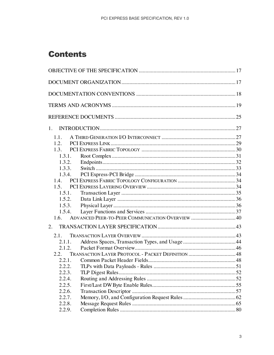
PCI EXPRESS BASE SPECIFICATION, REV 1.0 Contents OBJECTIVE OF THE SPECIFICATION ........................................................................ 17 DOCUMENT ORGANIZATION..................................................................................... 17 DOCUMENTATION CONVENTIONS .......................................................................... 18 TERMS AND ACRONYMS ............................................................................................ 19 REFERENCE DOCUMENTS .......................................................................................... 25 1. 2. 1.1. 1.2. 1.3. 1.4. 1.5. 1.6. 2.1. 2.2. 1.5.1. 1.5.2. 1.5.3. 1.5.4. 1.3.1. 1.3.2. 1.3.3. 1.3.4. INTRODUCTION..................................................................................................... 27 A THIRD GENERATION I/O INTERCONNECT ....................................................... 27 PCI EXPRESS LINK............................................................................................. 29 PCI EXPRESS FABRIC TOPOLOGY ...................................................................... 30 Root Complex ............................................................................................ 31 Endpoints................................................................................................... 32 Switch ........................................................................................................ 33 PCI Express-PCI Bridge ........................................................................... 34 PCI EXPRESS FABRIC TOPOLOGY CONFIGURATION ........................................... 34 PCI EXPRESS LAYERING OVERVIEW.................................................................. 34 Transaction Layer ..................................................................................... 35 Data Link Layer ........................................................................................ 36 Physical Layer........................................................................................... 36 Layer Functions and Services ................................................................... 37 ADVANCED PEER-TO-PEER COMMUNICATION OVERVIEW ................................. 40 TRANSACTION LAYER SPECIFICATION.......................................................... 43 TRANSACTION LAYER OVERVIEW...................................................................... 43 Address Spaces, Transaction Types, and Usage....................................... 44 Packet Format Overview........................................................................... 46 TRANSACTION LAYER PROTOCOL - PACKET DEFINITION................................... 48 Common Packet Header Fields................................................................. 48 TLPs with Data Payloads - Rules ............................................................. 51 TLP Digest Rules....................................................................................... 52 Routing and Addressing Rules .................................................................. 52 First/Last DW Byte Enable Rules.............................................................. 55 Transaction Descriptor ............................................................................. 57 Memory, I/O, and Configuration Request Rules ....................................... 62 Message Request Rules ............................................................................. 65 Completion Rules ...................................................................................... 80 2.2.1. 2.2.2. 2.2.3. 2.2.4. 2.2.5. 2.2.6. 2.2.7. 2.2.8. 2.2.9. 2.1.1. 2.1.2. 3
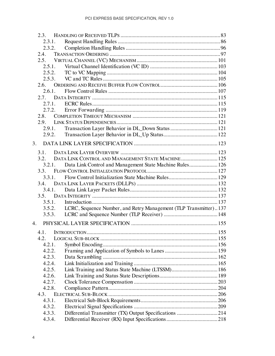
PCI EXPRESS BASE SPECIFICATION, REV 1.0 2.6.1. 2.8. 2.9. 2.9.1. 2.9.2. 2.3. 2.4. 2.5. 2.3.1. 2.3.2. 3.1. 3.2. 3.3. 3.4. 3.5. 2.7.1. 2.7.2. 2.6. 2.7. 2.5.1. 2.5.2. 2.5.3. HANDLING OF RECEIVED TLPS .......................................................................... 83 Request Handling Rules ............................................................................ 86 Completion Handling Rules ...................................................................... 96 TRANSACTION ORDERING .................................................................................. 97 VIRTUAL CHANNEL (VC) MECHANISM............................................................ 101 Virtual Channel Identification (VC ID) .................................................. 103 TC to VC Mapping .................................................................................. 104 VC and TC Rules..................................................................................... 105 ORDERING AND RECEIVE BUFFER FLOW CONTROL.......................................... 106 Flow Control Rules ................................................................................. 107 DATA INTEGRITY ............................................................................................. 115 ECRC Rules............................................................................................. 115 Error Forwarding ................................................................................... 119 COMPLETION TIMEOUT MECHANISM ............................................................... 121 LINK STATUS DEPENDENCIES........................................................................... 121 Transaction Layer Behavior in DL_Down Status................................... 121 Transaction Layer Behavior in DL_Up Status........................................ 122 3. DATA LINK LAYER SPECIFICATION .............................................................. 123 DATA LINK LAYER OVERVIEW ........................................................................ 123 DATA LINK CONTROL AND MANAGEMENT STATE MACHINE........................... 125 Data Link Control and Management State Machine Rules..................... 126 FLOW CONTROL INITIALIZATION PROTOCOL.................................................... 127 Flow Control Initialization State Machine Rules.................................... 129 DATA LINK LAYER PACKETS (DLLPS) ............................................................ 132 Data Link Layer Packet Rules................................................................. 132 DATA INTEGRITY ............................................................................................. 137 Introduction............................................................................................. 137 3.5.1. LCRC, Sequence Number, and Retry Management (TLP Transmitter).. 137 3.5.2. LCRC and Sequence Number (TLP Receiver) ........................................ 148 3.5.3. PHYSICAL LAYER SPECIFICATION ................................................................ 155 INTRODUCTION................................................................................................. 155 LOGICAL SUB-BLOCK....................................................................................... 155 Symbol Encoding..................................................................................... 156 Framing and Application of Symbols to Lanes ....................................... 159 Data Scrambling ..................................................................................... 162 Link Initialization and Training .............................................................. 165 Link Training and Status State Machine (LTSSM).................................. 186 Link Training and Status State Descriptions........................................... 189 Clock Tolerance Compensation .............................................................. 203 Compliance Pattern................................................................................. 204 ELECTRICAL SUB-BLOCK................................................................................. 206 Electrical Sub-Block Requirements......................................................... 206 Electrical Signal Specifications .............................................................. 209 Differential Transmitter (TX) Output Specifications .............................. 214 Differential Receiver (RX) Input Specifications...................................... 218 4.2.1. 4.2.2. 4.2.3. 4.2.4. 4.2.5. 4.2.6. 4.2.7. 4.2.8. 4.3.1. 4.3.2. 4.3.3. 4.3.4. 3.2.1. 3.3.1. 3.4.1. 4. 4.1. 4.2. 4.3. 4
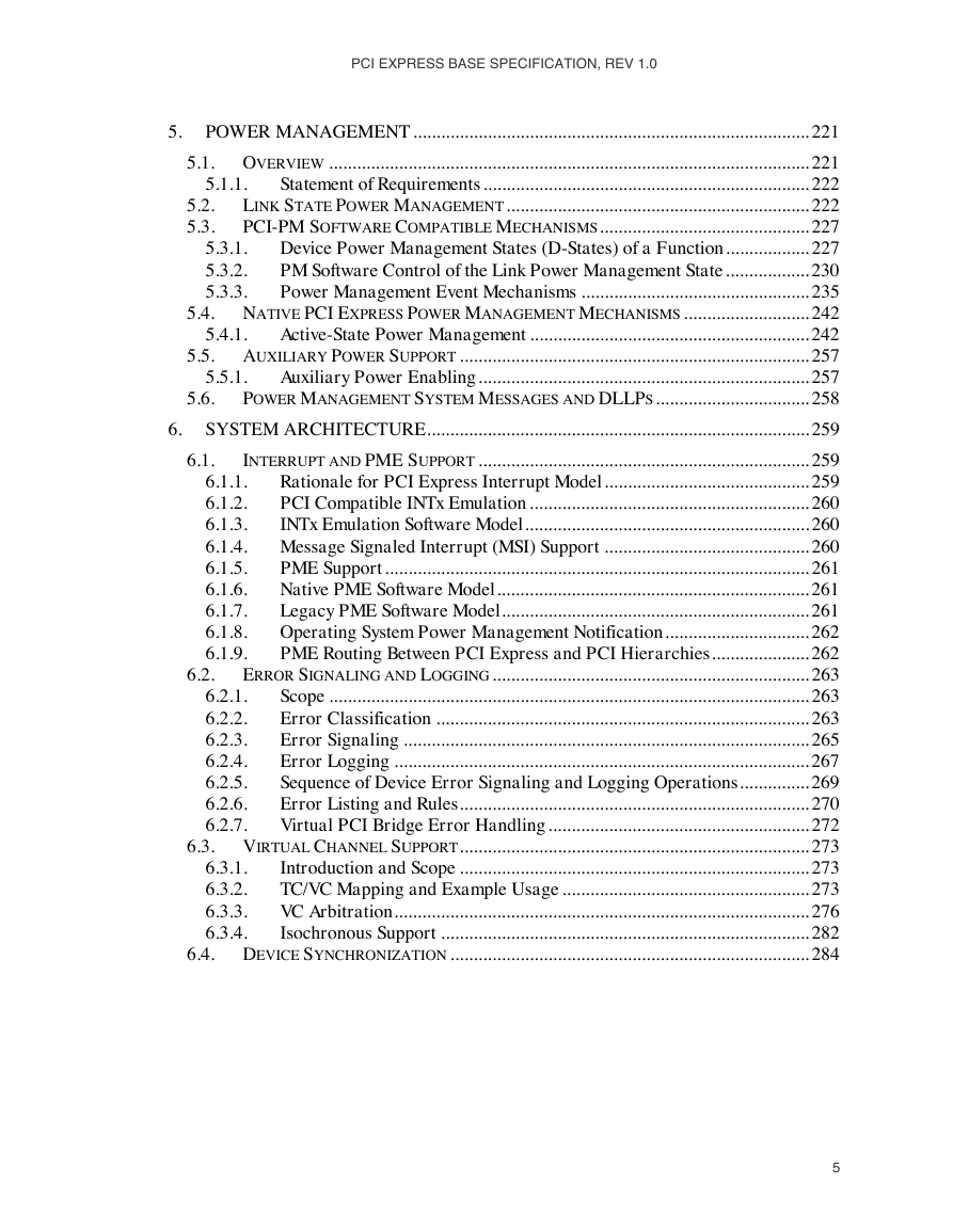
PCI EXPRESS BASE SPECIFICATION, REV 1.0 5.1. 5.2. 5.3. 5. 6. 5.4. 5.5. 5.6. 5.4.1. 5.5.1. 6.1. 5.1.1. 5.3.1. 5.3.2. 5.3.3. POWER MANAGEMENT..................................................................................... 221 OVERVIEW ....................................................................................................... 221 Statement of Requirements ...................................................................... 222 LINK STATE POWER MANAGEMENT................................................................. 222 PCI-PM SOFTWARE COMPATIBLE MECHANISMS............................................. 227 Device Power Management States (D-States) of a Function.................. 227 PM Software Control of the Link Power Management State.................. 230 Power Management Event Mechanisms ................................................. 235 NATIVE PCI EXPRESS POWER MANAGEMENT MECHANISMS ........................... 242 Active-State Power Management ............................................................ 242 AUXILIARY POWER SUPPORT ........................................................................... 257 Auxiliary Power Enabling....................................................................... 257 POWER MANAGEMENT SYSTEM MESSAGES AND DLLPS................................. 258 SYSTEM ARCHITECTURE.................................................................................. 259 INTERRUPT AND PME SUPPORT ....................................................................... 259 Rationale for PCI Express Interrupt Model............................................ 259 PCI Compatible INTx Emulation ............................................................ 260 INTx Emulation Software Model............................................................. 260 Message Signaled Interrupt (MSI) Support ............................................ 260 PME Support ........................................................................................... 261 Native PME Software Model................................................................... 261 Legacy PME Software Model.................................................................. 261 Operating System Power Management Notification............................... 262 PME Routing Between PCI Express and PCI Hierarchies..................... 262 ERROR SIGNALING AND LOGGING.................................................................... 263 Scope ....................................................................................................... 263 Error Classification ................................................................................ 263 Error Signaling ....................................................................................... 265 Error Logging ......................................................................................... 267 Sequence of Device Error Signaling and Logging Operations............... 269 Error Listing and Rules........................................................................... 270 Virtual PCI Bridge Error Handling........................................................ 272 VIRTUAL CHANNEL SUPPORT........................................................................... 273 Introduction and Scope ........................................................................... 273 TC/VC Mapping and Example Usage ..................................................... 273 VC Arbitration......................................................................................... 276 Isochronous Support ............................................................................... 282 DEVICE SYNCHRONIZATION ............................................................................. 284 6.1.1. 6.1.2. 6.1.3. 6.1.4. 6.1.5. 6.1.6. 6.1.7. 6.1.8. 6.1.9. 6.2.1. 6.2.2. 6.2.3. 6.2.4. 6.2.5. 6.2.6. 6.2.7. 6.3.1. 6.3.2. 6.3.3. 6.3.4. 6.2. 6.3. 6.4. 5
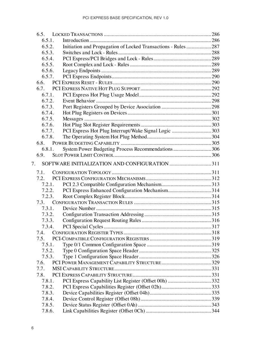
PCI EXPRESS BASE SPECIFICATION, REV 1.0 6.5. 6.8. 6.9. 7.1. 7.2. 7.3. 7.4. 7.5. 6.8.1. 6.6. 6.7. 6.5.1. 6.5.2. 6.5.3. 6.5.4. 6.5.5. 6.5.6. 6.5.7. 6.7.1. 6.7.2. 6.7.3. 6.7.4. 6.7.5. 6.7.6. 6.7.7. 6.7.8. LOCKED TRANSACTIONS .................................................................................. 286 Introduction............................................................................................. 286 Initiation and Propagation of Locked Transactions - Rules ................... 287 Switches and Lock - Rules....................................................................... 288 PCI Express/PCI Bridges and Lock - Rules............................................ 289 Root Complex and Lock - Rules .............................................................. 289 Legacy Endpoints .................................................................................... 289 PCI Express Endpoints............................................................................ 290 PCI EXPRESS RESET - RULES........................................................................... 290 PCI EXPRESS NATIVE HOT PLUG SUPPORT...................................................... 292 PCI Express Hot Plug Usage Model....................................................... 292 Event Behavior ........................................................................................ 298 Port Registers Grouped by Device Association ...................................... 298 Hot Plug Registers on Devices................................................................ 301 Messages ................................................................................................. 302 Hot Plug Slot Register Requirements...................................................... 303 PCI Express Hot Plug Interrupt/Wake Signal Logic .............................. 303 The Operating System Hot Plug Method................................................. 304 POWER BUDGETING CAPABILITY ..................................................................... 305 System Power Budgeting Process Recommendations............................. 306 SLOT POWER LIMIT CONTROL.......................................................................... 306 SOFTWARE INITIALIZATION AND CONFIGURATION................................ 311 CONFIGURATION TOPOLOGY............................................................................ 311 PCI EXPRESS CONFIGURATION MECHANISMS.................................................. 312 PCI 2.3 Compatible Configuration Mechanism...................................... 313 PCI Express Enhanced Configuration Mechanism................................. 314 Root Complex Register Block.................................................................. 314 CONFIGURATION TRANSACTION RULES ........................................................... 315 Device Number........................................................................................ 315 Configuration Transaction Addressing................................................... 315 Configuration Request Routing Rules ..................................................... 316 PCI Special Cycles .................................................................................. 317 CONFIGURATION REGISTER TYPES................................................................... 318 PCI-COMPATIBLE CONFIGURATION REGISTERS............................................... 319 Type 0/1 Common Configuration Space ................................................. 319 Type 0 Configuration Space Header....................................................... 325 Type 1 Configuration Space Header....................................................... 326 7.6. PCI POWER MANAGEMENT CAPABILITY STRUCTURE...................................... 329 7.7. MSI CAPABILITY STRUCTURE.......................................................................... 331 7.8. PCI EXPRESS CAPABILITY STRUCTURE............................................................ 331 PCI Express Capability List Register (Offset 00h) ................................. 332 PCI Express Capabilities Register (Offset 02h)...................................... 333 Device Capabilities Register (Offset 04h)............................................... 335 Device Control Register (Offset 08h)...................................................... 339 Device Status Register (Offset 0Ah)........................................................ 343 Link Capabilities Register (Offset 0Ch).................................................. 344 7.8.1. 7.8.2. 7.8.3. 7.8.4. 7.8.5. 7.8.6. 7.2.1. 7.2.2. 7.2.3. 7.3.1. 7.3.2. 7.3.3. 7.3.4. 7.5.1. 7.5.2. 7.5.3. 7. 6
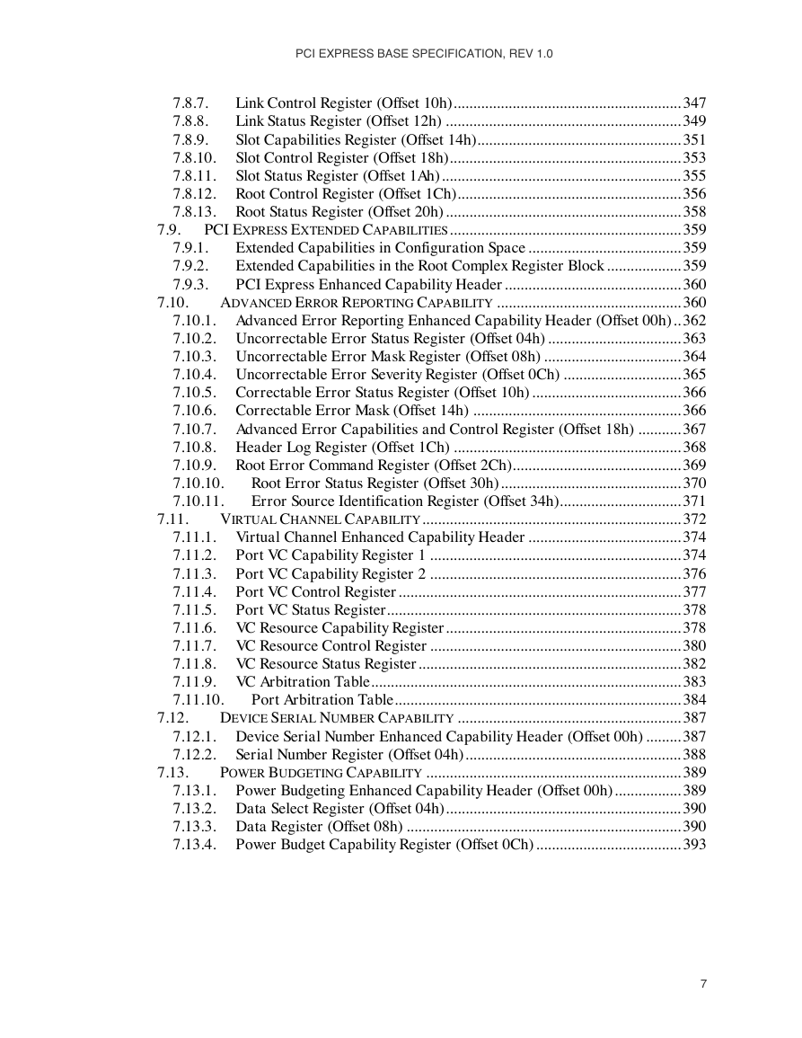
PCI EXPRESS BASE SPECIFICATION, REV 1.0 7.9. 7.9.1. 7.9.2. 7.9.3. 7.10. 7.8.7. 7.8.8. 7.8.9. 7.8.10. 7.8.11. 7.8.12. 7.8.13. Link Control Register (Offset 10h).......................................................... 347 Link Status Register (Offset 12h) ............................................................ 349 Slot Capabilities Register (Offset 14h).................................................... 351 Slot Control Register (Offset 18h)........................................................... 353 Slot Status Register (Offset 1Ah)............................................................. 355 Root Control Register (Offset 1Ch)......................................................... 356 Root Status Register (Offset 20h)............................................................ 358 PCI EXPRESS EXTENDED CAPABILITIES........................................................... 359 Extended Capabilities in Configuration Space ....................................... 359 Extended Capabilities in the Root Complex Register Block ................... 359 PCI Express Enhanced Capability Header............................................. 360 ADVANCED ERROR REPORTING CAPABILITY ............................................... 360 7.10.1. Advanced Error Reporting Enhanced Capability Header (Offset 00h).. 362 7.10.2. Uncorrectable Error Status Register (Offset 04h) .................................. 363 7.10.3. Uncorrectable Error Mask Register (Offset 08h) ................................... 364 7.10.4. Uncorrectable Error Severity Register (Offset 0Ch) .............................. 365 7.10.5. Correctable Error Status Register (Offset 10h) ...................................... 366 7.10.6. Correctable Error Mask (Offset 14h) ..................................................... 366 7.10.7. Advanced Error Capabilities and Control Register (Offset 18h) ........... 367 7.10.8. Header Log Register (Offset 1Ch) .......................................................... 368 Root Error Command Register (Offset 2Ch)........................................... 369 7.10.9. Root Error Status Register (Offset 30h).............................................. 370 7.10.10. 7.10.11. Error Source Identification Register (Offset 34h)............................... 371 VIRTUAL CHANNEL CAPABILITY.................................................................. 372 Virtual Channel Enhanced Capability Header ....................................... 374 Port VC Capability Register 1 ................................................................ 374 Port VC Capability Register 2 ................................................................ 376 Port VC Control Register........................................................................ 377 Port VC Status Register........................................................................... 378 VC Resource Capability Register............................................................ 378 VC Resource Control Register ................................................................ 380 VC Resource Status Register................................................................... 382 VC Arbitration Table............................................................................... 383 Port Arbitration Table......................................................................... 384 DEVICE SERIAL NUMBER CAPABILITY ......................................................... 387 7.12.1. Device Serial Number Enhanced Capability Header (Offset 00h) ......... 387 7.12.2. Serial Number Register (Offset 04h)....................................................... 388 POWER BUDGETING CAPABILITY ................................................................. 389 7.13.1. Power Budgeting Enhanced Capability Header (Offset 00h)................. 389 7.13.2. Data Select Register (Offset 04h)............................................................ 390 7.13.3. Data Register (Offset 08h) ...................................................................... 390 Power Budget Capability Register (Offset 0Ch)..................................... 393 7.13.4. 7.11.1. 7.11.2. 7.11.3. 7.11.4. 7.11.5. 7.11.6. 7.11.7. 7.11.8. 7.11.9. 7.11.10. 7.11. 7.12. 7.13. 7
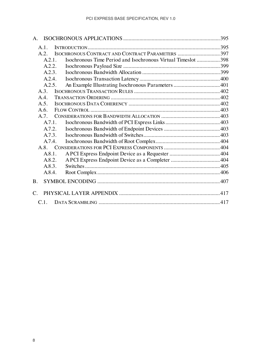
PCI EXPRESS BASE SPECIFICATION, REV 1.0 A. A.7.1. A.7.2. A.7.3. A.7.4. A.8.1. A.8.2. A.8.3. A.8.4. A.1. A.2. A.2.1. A.2.2. A.2.3. A.2.4. A.2.5. ISOCHRONOUS APPLICATIONS ....................................................................... 395 INTRODUCTION................................................................................................. 395 ISOCHRONOUS CONTRACT AND CONTRACT PARAMETERS ............................... 397 Isochronous Time Period and Isochronous Virtual Timeslot ................. 398 Isochronous Payload Size ....................................................................... 399 Isochronous Bandwidth Allocation ......................................................... 399 Isochronous Transaction Latency ........................................................... 400 An Example Illustrating Isochronous Parameters .................................. 401 ISOCHRONOUS TRANSACTION RULES ............................................................... 402 A.3. TRANSACTION ORDERING ................................................................................ 402 A.4. ISOCHRONOUS DATA COHERENCY ................................................................... 402 A.5. FLOW CONTROL ............................................................................................... 403 A.6. A.7. CONSIDERATIONS FOR BANDWIDTH ALLOCATION ........................................... 403 Isochronous Bandwidth of PCI Express Links........................................ 403 Isochronous Bandwidth of Endpoint Devices ......................................... 403 Isochronous Bandwidth of Switches........................................................ 403 Isochronous Bandwidth of Root Complex............................................... 404 A.8. CONSIDERATIONS FOR PCI EXPRESS COMPONENTS ......................................... 404 A PCI Express Endpoint Device as a Requester ..................................... 404 A PCI Express Endpoint Device as a Completer .................................... 404 Switches................................................................................................... 405 Root Complex .......................................................................................... 406 B. SYMBOL ENCODING .......................................................................................... 407 C. PHYSICAL LAYER APPENDIX .......................................................................... 417 C.1. DATA SCRAMBLING ......................................................................................... 417 8
分享到:
收藏