SCA103T Series
Data Sheet
SCA103T
SCA103T 系列是 3D-MEMS技术的单轴倾角传感器,其使用差分测量原理。其高校正精度结合极低的温度依赖性、高
分辨率、低噪声和传感元件坚固耐用的设计等特点,使得SCA103T是高精度水平仪器的理想选择。VTI的倾角传感器
由于具有过阻尼的传感元件,其对高频的振动不敏感,且其能承受的20000g的机械冲击。
差分倾角传感器系列
主 要特征:
• 测量范围: ±15° SCA103T-D04 以及
± 30° SCA103T-D05
•
0.001 分辨率 (10 Hz 带宽,模拟端输出)
• 传感单元受过阻尼控制,频率响应 (-3dB 18Hz)
•
坚固耐用设计高抗振性(20000g)
• 温度与时间下卓越的稳定性
• 使用差分测量原理,减小了共模误差和噪声
• 公制比例模拟电压输出
• 数字SPI倾角与温度数据输出
• 全面的故障自探测功能
o
True self test by deflecting the sensing
elements’ proof mass by electrostatic force.
o Continuous sensing element interconnection
o Continuous memory parity check.
failure check.
• 符合RoHS要求
• 可用无铅回流焊加工
• 水准测量仪
• 建筑物水平测量
12 VDD
• 单电源 +5 V 供电
应用:
• 平台水平与稳定
• 旋转激光水平仪
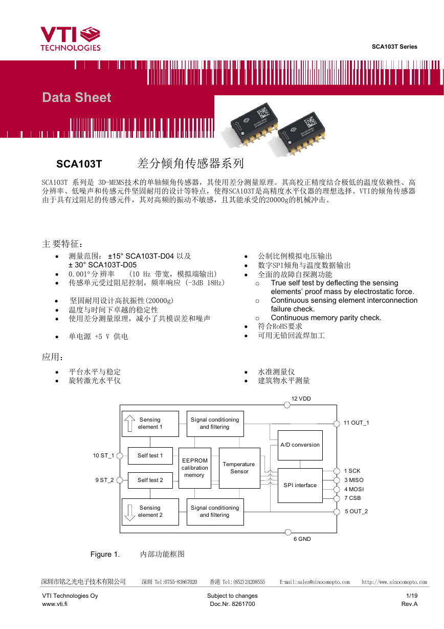
Sensing
element 1
Signal conditioning
and filtering
10 ST_1
Self test 1
9 ST_2
Self test 2
EEPROM
calibration
memory
Temperature
Sensor
Sensing
element 2
Signal conditioning
and filtering
Figure 1.
内部功能框图
11 OUT_1
1 SCK
3 MISO
4 MOSI
7 CSB
5 OUT_2
A/D conversion
SPI interface
6 GND
深圳市铭之光电子技术有限公司 深圳 Tel:0755-83867020 香港 Tel:(852)24208555 E-mail:sales@sinocomopto.com http://www.sinocomopto.com
VTI Technologies Oy
www.vti.fi
Subject to changes
Doc.Nr. 8261700
1/19
Rev.A
�
TABLE OF CONTENTS
SCA103T Series
The SCA103T Differential Inclinometer Series .......................................................................1
特征 .. ..............................................................................................................................................1
应用 .........................................................................................................................................1
Table of Contents .....................................................................................................................2
1 Electrical Specifications.....................................................................................................3
1.1 Absolute Maximum Ratings......................................................................................................3
1.2 Performance Characteristics....................................................................................................3
1.3 Electrical Characteristics..........................................................................................................4
1.4 SPI Interface DC Characteristics..............................................................................................4
1.5 SPI Interface AC Characteristics..............................................................................................4
1.6 SPI Interface Timing Specifications.........................................................................................5
1.7 Electrical Connection ................................................................................................................6
1.8 Typical Performance Characteristics.......................................................................................6
1.8.1 Additional External Compensation ........................................................................................7
2 Functional Description .......................................................................................................9
2.1 Differential Measurement..........................................................................................................9
2.2 Voltage to Angle Conversion....................................................................................................9
2.3 Ratiometric Output ..................................................................................................................10
2.4 SPI Serial Interface ..................................................................................................................10
2.5 Digital Output to Angle Conversion.......................................................................................13
2.6 Self Test and Failure Detection Modes..................................................................................14
2.7 Temperature Measurement.....................................................................................................15
3 Application Information....................................................................................................16
3.1 Recommended Circuit Diagrams and Printed Circuit Board Layouts ................................16
3.2 Recommended Printed Circuit Board Footprint ...................................................................17
4 Mechanical Specifications and Reflow Soldering ..........................................................17
4.1 Mechanical Specifications (Reference only).........................................................................17
4.2 Reflow Soldering......................................................................................................................18
5 Document Change Control...............................................................................................19
6 Contact Information ..........................................................................................................19
深圳市铭之光电子技术有限公司 深圳 Tel:0755-83867020 香港 Tel:(852)24208555 E-mail:sales@sinocomopto.com http://www.sinocomopto.com
VTI Technologies Oy
www.vti.fi
Subject to changes
Doc.Nr. 8261700
2/19
Rev.A
�
1 电气规格:
SCA103T Series
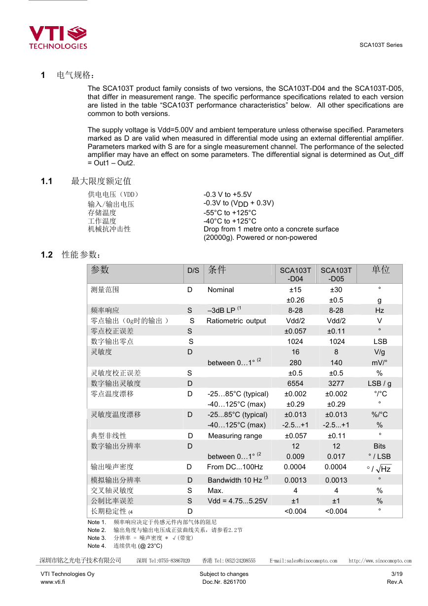
The SCA103T product family consists of two versions, the SCA103T-D04 and the SCA103T-D05,
that differ in measurement range. The specific performance specifications related to each version
are listed in the table “SCA103T performance characteristics” below. All other specifications are
common to both versions.
The supply voltage is Vdd=5.00V and ambient temperature unless otherwise specified. Parameters
marked as D are valid when measured in differential mode using an external differential amplifier.
Parameters marked with S are for a single measurement channel. The performance of the selected
amplifier may have an effect on some parameters. The differential signal is determined as Out_diff
= Out1 – Out2.
1.1 最大限度额定值
供电电压(VDD)
输入/输出电压
存储温度
工作温度
机械抗冲击性
1.2 性能 参数:
参数
-0.3 V to +5.5V
-0.3V to (VDD + 0.3V)
-55°C to +125°C
-40°C to +125°C
Drop from 1 metre onto a concrete surface
(20000g). Powered or non-powered
D/S 条件
SCA103T
SCA103T
Nominal
–3dB LP (1
-D04
±15
±0.26
8-28
Vdd/2
±0.057
-D05
±30
±0.5
8-28
Vdd/2
±0.11
1024 1024
between 0…1° (2
-25…85°C (typical)
-40…125°C (max)
-25...85°C (typical)
-40…125°C (max)
Measuring range
between 0…1° (2
From DC...100Hz
Bandwidth 10 Hz (3
Max.
Vdd = 4.75...5.25V
16
280
±0.5
6554
±0.002
±0.29
±0.013
-2.5...+1
±0.057
8
140
±0.5
3277
±0.002
±0.29
±0.013
-2.5...+1
±0.11
12
0.017
0.0004
0.0013
0.009
0.0004
0.0013
<0.004
<0.004
4
±1
4
±1
12
单位
°
g
Hz
V
°
LSB
V/g
mV/°
%
LSB / g
°/°C
°
%/°C
%
°
Bits
° / LSB
Hz
/°
°
%
%
°
测量范围
D
S
频率响应
零点输出(0g时的输出 ) S Ratiometric output
零点校正误差
数字输出零点
灵敏度
S
S
D
S
灵敏度校正误差
数字输出灵敏度
D
D
零点温度漂移
D
灵敏度温度漂移
典型非线性
数字输出分辨率
D
D
D
D
S
S
D
输出噪声密度
模拟输出分辨率
交叉轴灵敏度
公制比率误差
长期稳定性 (4
Note 1. 频率响应决定于传感元件内部气体的阻尼
Note 2. 输出角度与输出电压成正弦曲线关系,请参看2.2节
Note 3. 分辨率 = 噪声密度 * √(带宽)
Note 4. 连续供电 (@ 23°C)
深圳市铭之光电子技术有限公司 深圳 Tel:0755-83867020 香港 Tel:(852)24208555 E-mail:sales@sinocomopto.com http://www.sinocomopto.com
VTI Technologies Oy
www.vti.fi
Subject to changes
Doc.Nr. 8261700
3/19
Rev.A
�
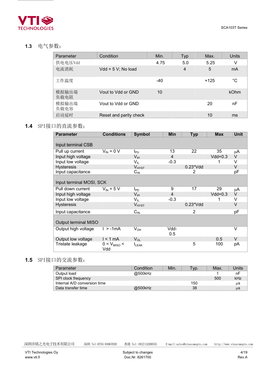
1.3 电气参数:
Parameter
供电电压Vdd
电流消耗
工作温度
模拟输出端
负载电阻
模拟输出端
负载电容
启动延时
1.4 SPI接口的直流参数:
SCA103T Series
Condition
Min.
4.75
Vdd = 5 V; No load
Vout to Vdd or GND
Vout to Vdd or GND
Reset and parity check
-40
10
Typ
5.0
4
Max.
5.25
5
+125
20
10
Units
V
mA
°C
kOhm
nF
ms
Parameter
Conditions
Symbol
Min
Typ
Max
Unit
Input terminal CSB
Pull up current
Input high voltage
Input low voltage
Hysteresis
Input capacitance
VIN = 0 V
Input terminal MOSI, SCK
Pull down current
Input high voltage
Input low voltage
Hysteresis
Input capacitance
VIN = 5 V
Output terminal MISO
Output high voltage
Output low voltage
Tristate leakage
1.5 SPI接口的交流参数:
I > -1mA
I < 1 mA
0 < VMISO <
Vdd
IPU
VIH
VIL
VHYST
CIN
IPD
VIH
VIL
VHYST
CIN
VOH
VOL
ILEAK
Parameter
Output load
SPI clock frequency
Internal A/D conversion time
Data transfer time
Condition
@500kHz
@500kHz
13
4
-0.3
9
4
-0.3
Vdd-
0.5
Min.
22
2
0.23*Vdd
35
µA
Vdd+0.3 V
V
V
pF
1
17
0.23*Vdd
2
5
29
µA
Vdd+0.3 V
V
V
pF
1
0.5
100
V
V
pA
Typ.
150
38
Max.
1
500
Units
nF
kHz
µs
µs
深圳市铭之光电子技术有限公司 深圳 Tel:0755-83867020 香港 Tel:(852)24208555 E-mail:sales@sinocomopto.com http://www.sinocomopto.com
VTI Technologies Oy
www.vti.fi
Subject to changes
Doc.Nr. 8261700
4/19
Rev.A
�
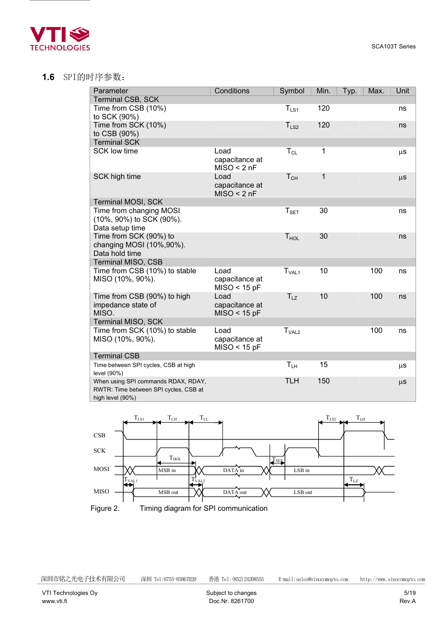
1.6 SPI的时序参数:
Parameter
Terminal CSB, SCK
Time from CSB (10%)
to SCK (90%)
Time from SCK (10%)
to CSB (90%)
Terminal SCK
SCK low time
SCK high time
Terminal MOSI, SCK
Time from changing MOSI
(10%, 90%) to SCK (90%).
Data setup time
Time from SCK (90%) to
changing MOSI (10%,90%).
Data hold time
Terminal MISO, CSB
Time from CSB (10%) to stable
MISO (10%, 90%).
Time from CSB (90%) to high
impedance state of
MISO.
Terminal MISO, SCK
Time from SCK (10%) to stable
MISO (10%, 90%).
SCA103T Series
Conditions
Symbol Min.
Typ. Max. Unit
Load
capacitance at
MISO < 2 nF
Load
capacitance at
MISO < 2 nF
Load
capacitance at
MISO < 15 pF
Load
capacitance at
MISO < 15 pF
Load
capacitance at
MISO < 15 pF
TLS1
TLS2
TCL
TCH
TSET
THOL
TVAL1
TLZ
120
120
1
1
30
30
10
10
TVAL2
TLH
TLH
15
150
ns
ns
µs
µs
ns
ns
100
ns
100
ns
100
ns
µs
µs
Terminal CSB
Time between SPI cycles, CSB at high
level (90%)
When using SPI commands RDAX, RDAY,
RWTR: Time between SPI cycles, CSB at
high level (90%)
CSB
SCK
Figure 2.
MOSI
MISO
TLS1
TCH
TCL
TLS2
TLH
THOL
MSB in
TSET
DATA in
TVAL1
TVAL2
MSB out
DATA out
Timing diagram for SPI communication
LSB in
LSB out
TLZ
深圳市铭之光电子技术有限公司 深圳 Tel:0755-83867020 香港 Tel:(852)24208555 E-mail:sales@sinocomopto.com http://www.sinocomopto.com
VTI Technologies Oy
www.vti.fi
Subject to changes
Doc.Nr. 8261700
5/19
Rev.A
�
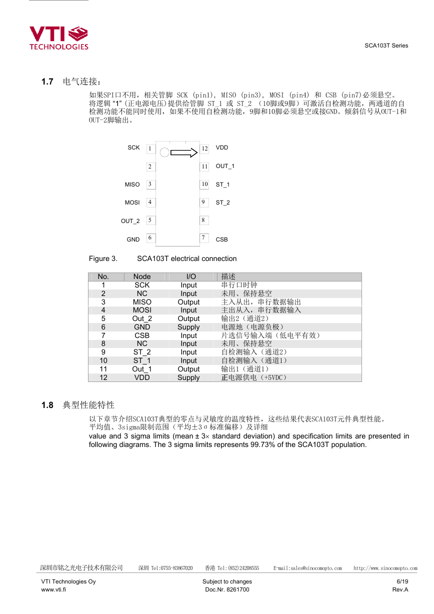
1.7 电气连接:
SCA103T Series
如果SPI口不用,相关管脚 SCK (pin1), MISO (pin3), MOSI (pin4) 和 CSB (pin7)必须悬空。
将逻辑 “1” (正电源电压)提供给管脚 ST_1 或 ST_2 (10脚或9脚)可激活自检测功能,两通道的自
检测功能不能同时使用,如果不使用自检测功能,9脚和10脚必须悬空或接GND。倾斜信号从OUT-1和
OUT-2脚输出。
SCK
SCK
Ext_C_1
MISO
MISO
MOSI
MOSI
OUT_2
OUT_2
VSS
GND
1
2
3
4
5
6
12
VDD
VDD
11
OUT_1
OUT_1
10
ST_1/Test_in
ST_1
9
8
7
ST_2
ST_2
Ext_C_2
CSB
CSB
Figure 3.
SCA103T electrical connection
No.
1
2
3
4
5
6
7
8
9
10
11
12
Node
SCK
NC
MISO
MOSI
Out_2
GND
CSB
NC
ST_2
ST_1
Out_1
VDD
I/O
Input
Input
Output
Input
Output
Supply
Input
Input
Input
Input
Output
Supply
描述
串行口时钟
未用、保持悬空
主入从出,串行数据输出
主出从入,串行数据输入
输出2(通道2)
电源地(电源负极)
片选信号输入端(低电平有效)
未用、保持悬空
自检测输入(通道2)
自检测输入(通道1)
输出1(通道1)
正 正电源供电(+5VDC)
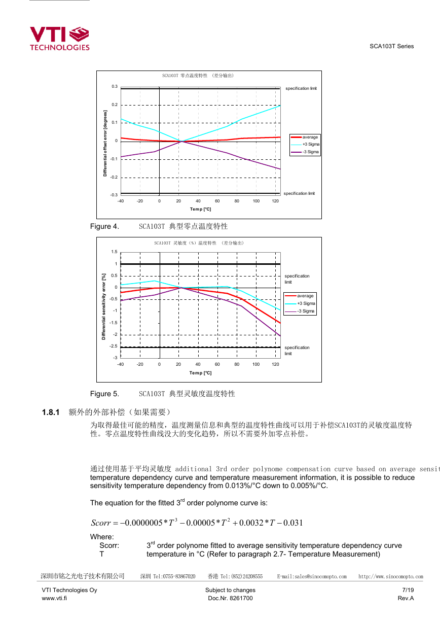
1.8 典型性能特性
以下章节介绍SCA103T典型的零点与灵敏度的温度特性,这些结果代表SCA103T元件典型性能。
平均值、3sigma限制范围(平均±3σ标准偏移)及详细
value and 3 sigma limits (mean ± 3× standard deviation) and specification limits are presented in
following diagrams. The 3 sigma limits represents 99.73% of the SCA103T population.
深圳市铭之光电子技术有限公司 深圳 Tel:0755-83867020 香港 Tel:(852)24208555 E-mail:sales@sinocomopto.com http://www.sinocomopto.com
VTI Technologies Oy
www.vti.fi
Subject to changes
Doc.Nr. 8261700
6/19
Rev.A
�
SCA103T 零点温度特性 (差分输出)
SCA103T Series
0.3
0.2
0.1
0
-0.1
]
s
e
e
r
g
e
d
[
r
o
r
r
e
t
e
s
f
f
o
l
a
i
t
n
e
r
e
f
f
i
D
-0.2
-0.3
-40
-20
0
20
40
60
80
100
120
Temp [°C]
Figure 4.
SCA103T 典型零点温度特性
SCA103T 灵敏度(%)温度特性 (差分输出)
1.5
1
]
%
0.5
[
r
o
r
r
e
y
t
i
v
i
t
i
s
n
e
s
l
a
i
t
n
e
r
e
f
f
i
D
0
-0.5
-1
-1.5
-2
-2.5
-3
-40
-20
0
20
40
60
80
100
120
Temp [°C]
specification limit
average
+3 Sigma
-3 Sigma
specification limit
specification
limit
average
+3 Sigma
-3 Sigma
specification
limit
Figure 5.
SCA103T 典型灵敏度温度特性
1.8.1 额外的外部补偿(如果需要)
为取得最佳可能的精度,温度测量信息和典型的温度特性曲线可以用于补偿SCA103T的灵敏度温度特
性。零点温度特性曲线没大的变化趋势,所以不需要外加零点补偿。
通过使用基于平均灵敏度 additional 3rd order polynome compensation curve based on average sensitivity
temperature dependency curve and temperature measurement information, it is possible to reduce
sensitivity temperature dependency from 0.013%/°C down to 0.005%/°C.
The equation for the fitted 3rd order polynome curve is:
Scorr
Where:
0000005
00005
0032
−=
.0
.0
.0
T
T
+
*
2
*
3
−
*
T
−
031.0
Scorr:
T
3rd order polynome fitted to average sensitivity temperature dependency curve
temperature in °C (Refer to paragraph 2.7- Temperature Measurement)
深圳市铭之光电子技术有限公司 深圳 Tel:0755-83867020 香港 Tel:(852)24208555 E-mail:sales@sinocomopto.com http://www.sinocomopto.com
VTI Technologies Oy
www.vti.fi
Subject to changes
Doc.Nr. 8261700
7/19
Rev.A
�
SCA103T Series
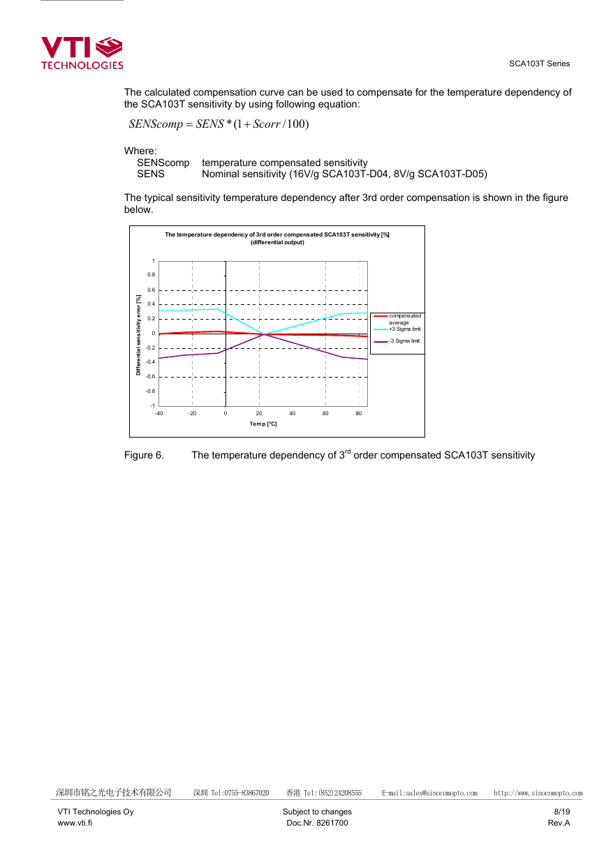
The calculated compensation curve can be used to compensate for the temperature dependency of
the SCA103T sensitivity by using following equation:
SENScomp
Where:
SENS
Scorr
)100
1(*
+
=
/
SENScomp
SENS
temperature compensated sensitivity
Nominal sensitivity (16V/g SCA103T-D04, 8V/g SCA103T-D05)
1
0.8
0.6
0.4
0.2
0
]
%
[
r
o
r
r
e
y
t
i
v
(differential output)
The temperature dependency of 3rd order compensated SCA103T sensitivity [%]
The typical sensitivity temperature dependency after 3rd order compensation is shown in the figure
below.
Figure 6.
The temperature dependency of 3rd order compensated SCA103T sensitivity
compensated
average
+3 Sigma limit
-3 Sigma limit
Temp [°C]
i
t
n
e
r
e
f
f
i
i
t
i
s
n
e
s
-0.8
-0.6
-0.4
-0.2
-40
-20
l
a
80
-1
D
0
20
40
60
深圳市铭之光电子技术有限公司 深圳 Tel:0755-83867020 香港 Tel:(852)24208555 E-mail:sales@sinocomopto.com http://www.sinocomopto.com
VTI Technologies Oy
www.vti.fi
Subject to changes
Doc.Nr. 8261700
8/19
Rev.A
�


 2023年江西萍乡中考道德与法治真题及答案.doc
 2012年重庆南川中考生物真题及答案.doc
 2013年江西师范大学地理学综合及文艺理论基础考研真题.doc
 2020年四川甘孜小升初语文真题及答案I卷.doc
 2020年注册岩土工程师专业基础考试真题及答案.doc
 2023-2024学年福建省厦门市九年级上学期数学月考试题及答案.doc
 2021-2022学年辽宁省沈阳市大东区九年级上学期语文期末试题及答案.doc
 2022-2023学年北京东城区初三第一学期物理期末试卷及答案.doc
 2018上半年江西教师资格初中地理学科知识与教学能力真题及答案.doc
 2012年河北国家公务员申论考试真题及答案-省级.doc
 2020-2021学年江苏省扬州市江都区邵樊片九年级上学期数学第一次质量检测试题及答案.doc
 2022下半年黑龙江教师资格证中学综合素质真题及答案.doc