www.femtoforum.org
Interference
Management
in UMTS
Femtocells
Published by the Femto Forum
December 2008
�
What is the Femto Forum?
The Femto Forum is the only organisation devoted to promoting femtocell technology
worldwide. It is a not-for-profit membership organisation, with membership open to providers
of femtocell technology and to operators with spectrum licences for providing mobile services.
The Forum is international, representing around 100 members from three continents and all
parts of the femtocell industry, including:
l Major operators
l Major infrastructure vendors
l Specialist femtocell vendors
l Vendors of components, subsystems, silicon and software necessary to create femtocells
The Femto Forum has three main aims:
l To promote adoption of femtocells by making available information to the industry and the
general public;
l To promote the rapid creation of appropriate open standards and interoperability for
femtocells;
l To encourage the development of an active ecosystem of femtocell providers to deliver
ongoing innovation of commercially and technically efficient solutions.
The Femto Forum is technology agnostic and independent. It is not a standards-setting body,
but works with standards organisations and regulators worldwide to provide an aggregated
view of the femtocell market.
A full current list of Femto Forum members and further information is available at
www.femtoforum.org
Interference Management in UMTS Femtocells is published by the Femto Forum
© December 2008. All rights reserved.
telephone +44 (0)845 644 5823 • fax +44 (0)845 644 5824 • email info@femtoforum.org • PO Box 23 GL11 5WA UK
www.femtoforum.org
�
Contents
1
2
3
4
5
6
7
8
Executive Summary ............................................................................................................................. 5
Femtocells, Femtocell Access Points and the Femto Forum ............................................................... 7
2.1 What are Femtocell Access Points? ................................................................................................. 7
2.2 What Do Femtocells Offer? ............................................................................................................. 8
2.3 What is the Femto Forum? .............................................................................................................. 9
Introduction ....................................................................................................................................... 10
3.1 Objectives and Methods of this Paper .......................................................................................... 10
Previous Work ................................................................................................................................... 12
Simulation Scenarios and Definitions ................................................................................................ 14
Abbreviations and Defined Terms ..................................................................................................... 18
Scenario A: Macrocell Downlink Interference to the Femtocell UE Receiver ................................... 19
7.1 Description .................................................................................................................................... 19
7.2 Analysis .......................................................................................................................................... 19
7.3 Extended scenario ......................................................................................................................... 24
7.4 Microcell coverage ........................................................................................................................ 26
7.5 Conclusions .................................................................................................................................... 29
Scenario B: Macrocell Uplink Interference to the Femtocell Receiver ............................................. 31
8.1 Description .................................................................................................................................... 31
8.2 Analysis .......................................................................................................................................... 31
8.2.1 HSUPA .................................................................................................................................... 35
8.3 Discussion ...................................................................................................................................... 37
8.4 Conclusions .................................................................................................................................... 38
Customer (MUE) impact ........................................................................................................ 39
8.4.1
8.4.2
Customer (FUE) Impact.......................................................................................................... 39
8.4.3 Mitigation techniques............................................................................................................ 39
9
Scenario C: Femtocell Downlink Interference to the Macrocell UE Receiver ................................... 40
9.1 Description .................................................................................................................................... 40
9.2 Analysis: ......................................................................................................................................... 40
9.3 Extended scenario – Capacity Analysis .......................................................................................... 42
9.4 Conclusions .................................................................................................................................... 46
9.4.1 Network and Customer Impact ............................................................................................. 46
10
Scenario D: Femtocell Uplink Interference to the Macrocell NodeB Receiver ................................. 47
Description................................................................................................................................. 47
Analysis ...................................................................................................................................... 48
10.1
10.2
�
10.2.1
Analysis of Scenario D‐ 12k2 Voice .................................................................................... 48
10.2.2
Analysis of Scenario D–HSUPA .......................................................................................... 56
11
10.3
Conclusions ................................................................................................................................ 57
Scenario E: Femtocell Downlink Interference to nearby Femtocell UE Receiver. ............................. 59
Description................................................................................................................................. 59
Analysis ...................................................................................................................................... 59
Conclusions: ............................................................................................................................... 63
Network and Customer Impact ......................................................................................... 64
11.3.1
11.1
11.2
11.3
12
Scenario F: Femtocell Uplink Interference to Nearby Femtocell Receivers ...................................... 65
Description................................................................................................................................. 65
Analysis ...................................................................................................................................... 65
Assumptions and Method ..................................................................................................... 66
1.1.
12.1
12.2
13
14
14.1
14.2
12.3
13.1
13.2
13.3
Conclusions ................................................................................................................................ 67
Scenario G: Macrocell Downlink Interference to an adjacent channel Femtocell UE Receiver ........ 68
Description................................................................................................................................. 68
Analysis ...................................................................................................................................... 68
Conclusions ................................................................................................................................ 71
Scenario H: Macrocell Uplink Interference to the adjacent channel Femtocell Receiver ................. 72
Description................................................................................................................................. 72
Analysis ...................................................................................................................................... 73
Parameter settings ............................................................................................................ 73
14.2.1
14.2.2
Impact of MUE interference on AMR ................................................................................ 75
14.2.3
Impact of MUE interference on HSUPA ............................................................................. 78
14.3
Conclusions ................................................................................................................................ 80
Femto System Impact ........................................................................................................ 81
14.3.1
14.3.2 Mitigation techniques........................................................................................................ 81
15
Scenario I: Femtocell Downlink Interference to the adjacent channel macrocell UE Receiver ........ 82
Description................................................................................................................................. 82
Analysis ...................................................................................................................................... 83
Parameter settings ............................................................................................................ 83
15.2.1
15.1
15.2
15.2.2
Impact of Femtocell interference on AMR service ............................................................ 85
15.2.3
Impact of Femtocell interference on HSDPA ..................................................................... 87
15.3
Conclusions ................................................................................................................................ 88
Customer (MUE) Impact .................................................................................................... 89
15.3.1
15.3.2 Mitigation techniques........................................................................................................ 89
16
Scenario J: Femtocell Uplink Interference to the adjacent channel Macrocell NodeB Receiver (J) . 90
© 2008 Femto Forum Limited
page 2
�
16.1
16.2
Description................................................................................................................................. 90
Analysis ...................................................................................................................................... 91
Analysis of Scenario J.1 ‐12k2 Voice service ...................................................................... 91
16.2.1
16.2.2
Analysis of Scenario J – HSUPA .......................................................................................... 96
16.3
Conclusions ................................................................................................................................ 98
16.3.1 Maximum Femto UE allowed transmission Power Proposal ............................................ 98
17 Downlink and Uplink Scenarios Modelling Power Control Techniques for Interference Mitigation
102
17.1
setting
System Simulation of the Downlink Scenario, with specific focus on HNB transmit power
102
Description ....................................................................................................................... 102
17.1.1
17.1.2
Analysis ............................................................................................................................ 102
17.1.3
Conclusions ...................................................................................................................... 117
17.2
System Level Simulation of the Uplink Scenario (idealised network configuration) .............. 118
Description ....................................................................................................................... 118
17.2.1
17.2.2
Analysis ............................................................................................................................ 118
17.2.3
Conclusions ...................................................................................................................... 124
17.3
System Level Simulation of the Uplink Scenario (real network configuration) ....................... 124
Description ....................................................................................................................... 124
17.3.1
17.3.2
Analysis ............................................................................................................................ 124
17.3.3
Conclusions ...................................................................................................................... 126
18 Detailed Summary of Findings ......................................................................................................... 128
19 Overall Conclusions ......................................................................................................................... 133
Further Reading ............................................................................................................................... 134
20
Scenario A ................................................................................................................................ 134
Scenario B ................................................................................................................................ 134
Scenario C ................................................................................................................................ 134
Scenario D ................................................................................................................................ 134
Scenario E ................................................................................................................................ 134
Scenario F ................................................................................................................................ 134
Scenario G ................................................................................................................................ 135
Scenario H ................................................................................................................................ 135
Scenario I ................................................................................................................................. 135
Scenario J ............................................................................................................................. 135
Scenarios – Section 17 ......................................................................................................... 135
References ....................................................................................................................................... 136
Simulation Parameters and Path Loss Models ................................................................................ 141
Simulation parameters ............................................................................................................ 141
20.1
20.2
20.3
20.4
20.5
20.6
20.7
20.8
20.9
20.10
20.11
21
22
22.1
© 2008 Femto Forum Limited
page 3
�
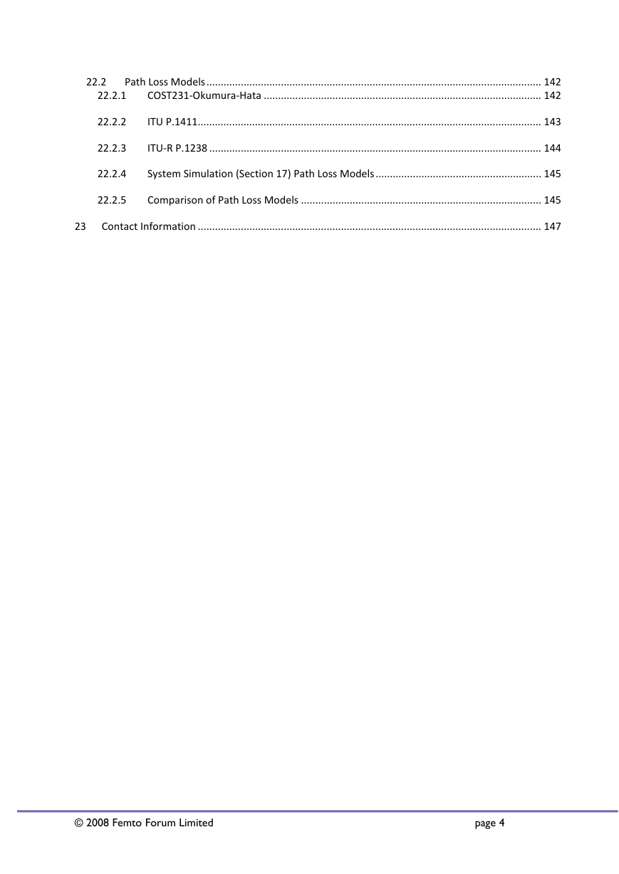
22.2
Path Loss Models ..................................................................................................................... 142
COST231‐Okumura‐Hata ................................................................................................. 142
22.2.1
22.2.2
ITU P.1411........................................................................................................................ 143
22.2.3
ITU‐R P.1238 .................................................................................................................... 144
22.2.4
System Simulation (Section 17) Path Loss Models .......................................................... 145
22.2.5
Comparison of Path Loss Models .................................................................................... 145
Contact Information ........................................................................................................................ 147
23
© 2008 Femto Forum Limited
page 4
�
1 Executive Summary
Femtocells, by virtue of their simultaneous small size, low cost and high performance, are a potentially
industry‐changing disruptive shift in technology for radio access in cellular networks. Their small size means
that the spectrum efficiency they can attain is much greater than that achievable using macrocells alone.
Their low cost means they can be deployed as consumer equipment, reducing the capital load and operating
expenses of the host network. And their high performance means that all this can be gained at no loss of
service to the customer, and in many cases, owing to the improved link budgets, improved service.
However, for these apparent benefits to translate into real advantage for network operator and
consumer alike, we must answer serious questions about the interaction between the femtocell technology
and the host macrocellular radio network into which they are deployed. If femtocells can only achieve their
potential by disrupting the macro network, then they will be relegated to niche deployments, of little overall
relevance to next generation networks. On the other hand, if the interactions between macro and femto
radio layers can be managed to the benefit of all, then their properties (in terms of lowered cost, improved
spectrum efficiency and link budget and general performance) can be fully realised, and femtocells will find
themselves an essential component of all future radio access network designs
So, what are these interactions, and how can they be managed, and what does that all mean for the
technology, to the operator and to the consumer? These are the questions that this paper is helping to
answer. In doing so, it has deliberately maintained a tight focus, according to the priorities of its authors. It
is exclusively concerned with W‐CDMA as an air interface technology. (Other teams within Femto Forum are
looking at other air interfaces.) It is, at this edition, concerned exclusively with operation around 2GHz – this
being seen as the most important frequency range for early, in‐building deployment. (Further editions of
this paper will look at 850/900MHz deployment.) And it is exclusively a theoretical treatment, using link
level and system level simulations to draw its conclusions, though we expect to back these conclusions up in
due course with trial campaign data. In view of the residential application that femtocells are addressing,
this paper is also exclusively concerned with femtocells operating with closed user groups. Perhaps most
importantly, this paper “stands on the shoulders of giants”, drawing on the great mass of study work that
has already been undertaken by 3GPP RAN4 participants in analysing these issues, and referencing them for
further reading.
The interacting components of the femto‐enabled network include femtocells themselves, which can be
interacting in their downlinks with other nearby femtocells and macro cells; macrocells, which interact with
nearby femtocells; users and user equipment (UEs) which by virtue of intentional radio links to femtocells
© 2008 Femto Forum Limited
page 5
�
and macrocells, may be causing unintentional interactions with both.
In approach, this paper has chosen to look at extreme cases, to complement as far as possible the
average, or typical scenarios that RAN4 has already studied in 3GPP. In the main, the analysis has shown up
internal contradictions in those extreme cases – meaning that they will never occur. For instance: analysing
the case when the UE is operating at full power in its uplink towards a femtocell is shown to occur only when
the macro cell is nearby – in which case the macro downlink signal is so strong that the UE will never select
the femtocell over the macrocell. This contradiction shows, for instance, that the high noise rise that a UE
could in principle cause will happily never occur. In other cases, the extreme cases are avoided by uplink
power‐capping or other techniques recommended in the paper.
With these extreme cases disarmed, then of the many potential interactions between UEs, femtocells
and macrocells, the summary conclusion that we have reached, in common with other studies, is that in
order to be successful, femtocell technology must manage three things,
Femtocell downlink power – if femtocells transmit inappropriately loudly, then the cell may be
large, but non‐members of the closed user group will experience a loss of service close to the
femtocell. On the other hand, if the femtocell transmits too softly, then non‐group members
will be unaffected, but the femtocell coverage area will be too small to give benefit to its users.
Femtocell receiver gain – since UEs have a minimum transmit power below which they cannot
operate, and since they can approach the femtocell far more closely than they can a normal
macrocell, we must reduce the femtocell receiver gain, so that nearby UEs do not overload it.
This must be done dynamically, so that distant UEs are not transmitting at high power, and
contributing to macro network noise rise on a permanent basis.
UE uplink power – since UEs transmitting widely at high power can generate unacceptable noise
rise interference in the macro network, we signal a maximum power to the UE (a power cap) to
ensure that it hands off to the macro network in good time, rather than transmit at too high a
power in clinging to the femtocell.
We have also shown that, with these issues addressed, the net effect of deploying femtocells alongside a
macro network is significantly to increase its capacity. In numerical terms, and in terms of the simulated
scenario, the available air interface data capacity is shown to increase by over a hundredfold by the
introduction of femtocells.
© 2008 Femto Forum Limited
page 6
�



 2023年江西萍乡中考道德与法治真题及答案.doc
 2012年重庆南川中考生物真题及答案.doc
 2013年江西师范大学地理学综合及文艺理论基础考研真题.doc
 2020年四川甘孜小升初语文真题及答案I卷.doc
 2020年注册岩土工程师专业基础考试真题及答案.doc
 2023-2024学年福建省厦门市九年级上学期数学月考试题及答案.doc
 2021-2022学年辽宁省沈阳市大东区九年级上学期语文期末试题及答案.doc
 2022-2023学年北京东城区初三第一学期物理期末试卷及答案.doc
 2018上半年江西教师资格初中地理学科知识与教学能力真题及答案.doc
 2012年河北国家公务员申论考试真题及答案-省级.doc
 2020-2021学年江苏省扬州市江都区邵樊片九年级上学期数学第一次质量检测试题及答案.doc
 2022下半年黑龙江教师资格证中学综合素质真题及答案.doc