ST7735S
132RGB x 162dot 262K Color with Frame Memory
Single-Chip TFT Controller/Driver
Datasheet
Version 1.5
2015/ 3
Sitronix Technology Corp. reserves the right to change the contents in this
document without prior notice.
�
ST7735S
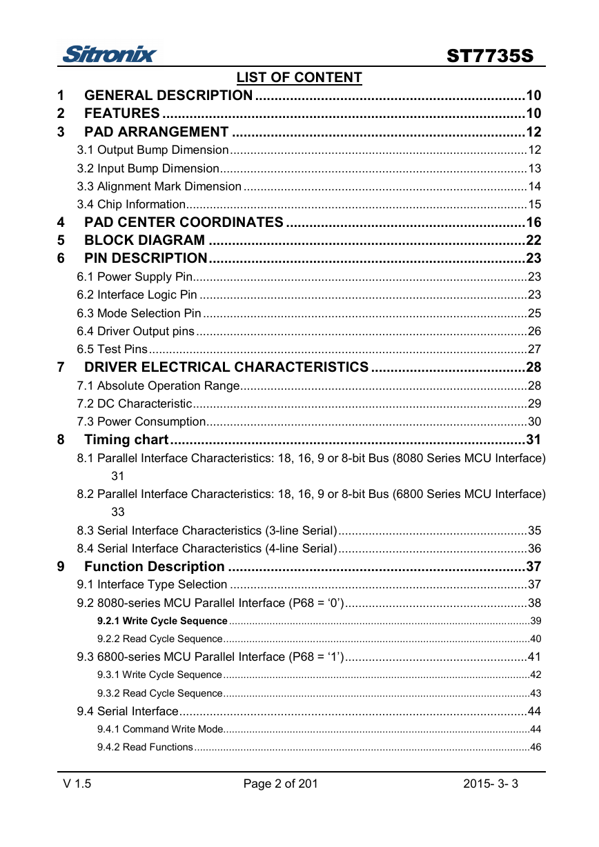
LIST OF CONTENT
1 GENERAL DESCRIPTION ......................................................................10
2 FEATURES ..............................................................................................10
3 PAD ARRANGEMENT ............................................................................12
3.1 Output Bump Dimension........................................................................................12
3.2 Input Bump Dimension...........................................................................................13
3.3 Alignment Mark Dimension ....................................................................................14
3.4 Chip Information.....................................................................................................15
4 PAD CENTER COORDINATES ..............................................................16
5 BLOCK DIAGRAM ..................................................................................22
6 PIN DESCRIPTION..................................................................................23
6.1 Power Supply Pin...................................................................................................23
6.2 Interface Logic Pin .................................................................................................23
6.3 Mode Selection Pin................................................................................................25
6.4 Driver Output pins..................................................................................................26
6.5 Test Pins................................................................................................................27
7 DRIVER ELECTRICAL CHARACTERISTICS ........................................28
7.1 Absolute Operation Range.....................................................................................28
7.2 DC Characteristic...................................................................................................29
7.3 Power Consumption...............................................................................................30
8 Timing chart............................................................................................31
8.1 Parallel Interface Characteristics: 18, 16, 9 or 8-bit Bus (8080 Series MCU Interface)
8.2 Parallel Interface Characteristics: 18, 16, 9 or 8-bit Bus (6800 Series MCU Interface)
8.3 Serial Interface Characteristics (3-line Serial)........................................................35
8.4 Serial Interface Characteristics (4-line Serial)........................................................36
9 Function Description .............................................................................37
9.1 Interface Type Selection ........................................................................................37
9.2 8080-series MCU Parallel Interface (P68 = ‘0’)......................................................38
9.2.1 Write Cycle Sequence........................................................................................................39
9.2.2 Read Cycle Sequence..........................................................................................................40
9.3 6800-series MCU Parallel Interface (P68 = ‘1’)......................................................41
9.3.1 Write Cycle Sequence..........................................................................................................42
9.3.2 Read Cycle Sequence..........................................................................................................43
9.4 Serial Interface.......................................................................................................44
9.4.1 Command Write Mode..........................................................................................................44
9.4.2 Read Functions....................................................................................................................46
31
33
V 1.5 Page 2 of 201 2015- 3- 3
�
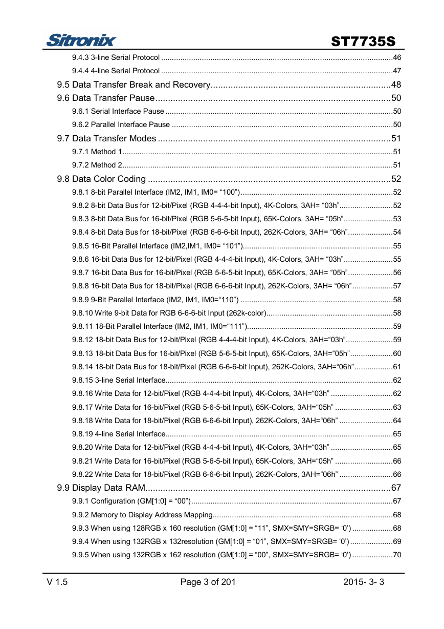
ST7735S
9.4.3 3-line Serial Protocol ............................................................................................................46
9.4.4 4-line Serial Protocol ............................................................................................................47
9.5 Data Transfer Break and Recovery........................................................................48
9.6 Data Transfer Pause..............................................................................................50
9.6.1 Serial Interface Pause ..........................................................................................................50
9.6.2 Parallel Interface Pause .......................................................................................................50
9.7 Data Transfer Modes .............................................................................................51
9.7.1 Method 1..............................................................................................................................51
9.7.2 Method 2..............................................................................................................................51
9.8 Data Color Coding .................................................................................................52
9.8.1 8-bit Parallel Interface (IM2, IM1, IM0= “100”).......................................................................52
9.8.2 8-bit Data Bus for 12-bit/Pixel (RGB 4-4-4-bit Input), 4K-Colors, 3AH= “03h”.........................52
9.8.3 8-bit Data Bus for 16-bit/Pixel (RGB 5-6-5-bit Input), 65K-Colors, 3AH= “05h”.......................53
9.8.4 8-bit Data Bus for 18-bit/Pixel (RGB 6-6-6-bit Input), 262K-Colors, 3AH= “06h”.....................54
9.8.5 16-Bit Parallel Interface (IM2,IM1, IM0= “101”)......................................................................55
9.8.6 16-bit Data Bus for 12-bit/Pixel (RGB 4-4-4-bit Input), 4K-Colors, 3AH= “03h”.......................55
9.8.7 16-bit Data Bus for 16-bit/Pixel (RGB 5-6-5-bit Input), 65K-Colors, 3AH= “05h”.....................56
9.8.8 16-bit Data Bus for 18-bit/Pixel (RGB 6-6-6-bit Input), 262K-Colors, 3AH= “06h”...................57
9.8.9 9-Bit Parallel Interface (IM2, IM1, IM0=“110”) .......................................................................58
9.8.10 Write 9-bit Data for RGB 6-6-6-bit Input (262k-color)...........................................................58
9.8.11 18-Bit Parallel Interface (IM2, IM1, IM0=“111”)....................................................................59
9.8.12 18-bit Data Bus for 12-bit/Pixel (RGB 4-4-4-bit Input), 4K-Colors, 3AH=“03h”......................59
9.8.13 18-bit Data Bus for 16-bit/Pixel (RGB 5-6-5-bit Input), 65K-Colors, 3AH=“05h”....................60
9.8.14 18-bit Data Bus for 18-bit/Pixel (RGB 6-6-6-bit Input), 262K-Colors, 3AH=“06h”..................61
9.8.15 3-line Serial Interface..........................................................................................................62
9.8.16 Write Data for 12-bit/Pixel (RGB 4-4-4-bit Input), 4K-Colors, 3AH=“03h” .............................62
9.8.17 Write Data for 16-bit/Pixel (RGB 5-6-5-bit Input), 65K-Colors, 3AH=“05h” ...........................63
9.8.18 Write Data for 18-bit/Pixel (RGB 6-6-6-bit Input), 262K-Colors, 3AH=“06h” .........................64
9.8.19 4-line Serial Interface..........................................................................................................65
9.8.20 Write Data for 12-bit/Pixel (RGB 4-4-4-bit Input), 4K-Colors, 3AH=“03h” .............................65
9.8.21 Write Data for 16-bit/Pixel (RGB 5-6-5-bit Input), 65K-Colors, 3AH=“05h” ...........................66
9.8.22 Write Data for 18-bit/Pixel (RGB 6-6-6-bit Input), 262K-Colors, 3AH=“06h” .........................66
9.9 Display Data RAM..................................................................................................67
9.9.1 Configuration (GM[1:0] = “00”)..............................................................................................67
9.9.2 Memory to Display Address Mapping....................................................................................68
9.9.3 When using 128RGB x 160 resolution (GM[1:0] = “11”, SMX=SMY=SRGB= ‘0’) ...................68
9.9.4 When using 132RGB x 132resolution (GM[1:0] = “01”, SMX=SMY=SRGB= ‘0’) ....................69
9.9.5 When using 132RGB x 162 resolution (GM[1:0] = “00”, SMX=SMY=SRGB= ‘0’) ...................70
V 1.5 Page 3 of 201 2015- 3- 3
�
ST7735S
9.9.6 Normal Display On or Partial Mode On.................................................................................71
9.9.7 When using 128RGB x 160 resolution (GM[1:0] = “11”) ........................................................71
9.9.8 When using 128RGB x 160 resolution (GM[1:0] = “01”) ........................................................72
9.9.9 When using 132RGB x 162 resolution (GM[1:0] = “00”) ........................................................73
9.10 Address Counter..................................................................................................74
9.11 Memory Data Write/ Read Direction ....................................................................75
9.11.1 When 128RGBx160 (GM= “11”) .........................................................................................75
9.11.2 When 132RGBx132 (GM= “01”) .........................................................................................75
9.11.3 When 132RGBx162 (GM= “00”) .........................................................................................76
9.11.4 Frame Data Write Direction According to the MADCTL Parameters (MV, MX and MY)........77
9.11.5 Scroll Address Circuit .........................................................................................................78
9.11.6 Vertical Scroll Mode ...........................................................................................................78
9.11.7 Vertical Scroll Example.......................................................................................................79
9.11.8 Case 1: TFA + VSA + BFA<162 .........................................................................................79
9.11.9 Case 2: TFA + VSA + BFA=162 (Rolling Scrolling) .............................................................80
9.12 Tearing Effect Output Line ...................................................................................81
9.12.1 Tearing Effect Line Modes..................................................................................................81
9.12.2 Tearing Effect Line Timings ................................................................................................82
9.12.3 Example 1: MPU Write is faster than panel read.................................................................83
9.12.4 Example 2: MPU Write is slower than panel read................................................................84
9.13 Power ON/OFF Sequence ...................................................................................85
9.13.1 Uncontrolled Power Off ......................................................................................................86
9.14 Power Level Definition .........................................................................................87
9.14.1 Power Level .......................................................................................................................87
9.14.2 Power Flow Chart...............................................................................................................88
9.15 Reset Table..........................................................................................................89
9.15.1 Reset Table(Default Value, GM[1:0]=“11”, 128RGB x 160) .................................................89
9.15.2 Reset Table (GM[1:0]= “01”, 132RGB x 132) ......................................................................90
9.15.3 Reset Table (GM[1:0]= “00”, 132RGB x 162) ......................................................................91
9.16 Module Input/Output Pins.....................................................................................92
9.16.1 Output or Bi-directional (I/O) Pins .......................................................................................92
9.17 Reset Timing........................................................................................................93
9.18 Color Depth Conversion Look Up Tables.............................................................94
9.18.1 65536 Color to 262,144 Color.............................................................................................94
9.18.2 4096 Color to 262,144 Color...............................................................................................98
9.19 Sleep Out-Command and Self-Diagnostic Functions of the Display Module......100
9.19.1 Register Loading Detection ..............................................................................................100
9.19.2 Functionality Detection .....................................................................................................101
V 1.5 Page 4 of 201 2015- 3- 3
�
ST7735S
9.19.3 Chip Attachment Detection (Optional)...............................................................................102
9.19.4 Display Glass Break Detection (Optional) .........................................................................103
10 COMMAND ............................................................................................104
10.1 System Function Command List and Description ..............................................104
10.1.1 NOP (00h)........................................................................................................................107
10.1.2 SWRESET (01h): Software Reset ....................................................................................108
10.1.3 RDDID (04h): Read Display ID .........................................................................................109
10.1.4 RDDST (09h): Read Display Status..................................................................................110
10.1.5 RDDPM (0Ah): Read Display Power Mode .......................................................................112
10.1.6 RDDMADCTL (0Bh): Read Display MADCTL ...................................................................113
10.1.7 RDDCOLMOD (0Ch): Read Display Pixel Format.............................................................114
10.1.8 RDDIM (0Dh): Read Display Image Mode ........................................................................115
10.1.9 RDDSM (0Eh): Read Display Signal Mode .......................................................................116
10.1.10 RDDSDR (0Fh): Read Display Self-Diagnostic Result.....................................................118
10.1.11 SLPIN (10h): Sleep In.....................................................................................................119
10.1.12 SLPOUT (11h): Sleep Out..............................................................................................120
10.1.13 PTLON (12h): Partial Display Mode On ..........................................................................121
10.1.14 NORON (13h): Normal Display Mode On........................................................................122
10.1.15 INVOFF (20h): Display Inversion Off...............................................................................123
10.1.16 INVON (21h): Display Inversion On ................................................................................124
10.1.17 GAMSET (26h): Gamma Set ..........................................................................................125
10.1.18 DISPOFF (28h): Display Off ...........................................................................................126
10.1.19 DISPON (29h): Display On .............................................................................................127
10.1.20 CASET (2Ah): Column Address Set................................................................................128
10.1.21 RASET (2Bh): Row Address Set.....................................................................................130
10.1.22 RAMWR (2Ch): Memory Write........................................................................................132
10.1.23 RGBSET (2Dh): Color Setting for 4K, 65K and 262K ......................................................133
10.1.24 RAMRD (2Eh): Memory Read ........................................................................................134
10.1.25 PTLAR (30h): Partial Area ..............................................................................................135
10.1.26 SCRLAR (33h): Scroll Area Set ......................................................................................137
10.1.27 TEOFF (34h): Tearing Effect Line OFF...........................................................................139
10.1.28 TEON (35h): Tearing Effect Line ON ..............................................................................140
10.1.29 MADCTL (36h): Memory Data Access Control ................................................................142
10.1.30 VSCSAD: Vertical Scroll Start Address of RAM (37h) .....................................................145
10.1.31 IDMOFF (38h): Idle Mode Off .........................................................................................147
10.1.32 IDMON (39h): Idle Mode On...........................................................................................148
10.1.33 COLMOD (3Ah): Interface Pixel Format..........................................................................150
10.1.34 RDID1 (DAh): Read ID1 Value........................................................................................151
V 1.5 Page 5 of 201 2015- 3- 3
�
ST7735S
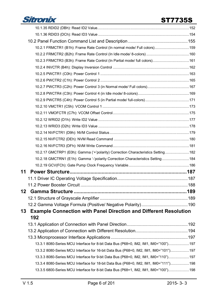
10.1.35 RDID2 (DBh): Read ID2 Value........................................................................................152
10.1.36 RDID3 (DCh): Read ID3 Value .......................................................................................154
10.2 Panel Function Command List and Description .................................................155
10.2.1 FRMCTR1 (B1h): Frame Rate Control (In normal mode/ Full colors).................................159
10.2.2 FRMCTR2 (B2h): Frame Rate Control (In Idle mode/ 8-colors) .........................................160
10.2.3 FRMCTR3 (B3h): Frame Rate Control (In Partial mode/ full colors)...................................161
10.2.4 INVCTR (B4h): Display Inversion Control .........................................................................162
10.2.5 PWCTR1 (C0h): Power Control 1 .....................................................................................163
10.2.6 PWCTR2 (C1h): Power Control 2 .....................................................................................165
10.2.7 PWCTR3 (C2h): Power Control 3 (in Normal mode/ Full colors)........................................167
10.2.8 PWCTR4 (C3h): Power Control 4 (in Idle mode/ 8-colors).................................................169
10.2.9 PWCTR5 (C4h): Power Control 5 (in Partial mode/ full-colors)..........................................171
10.2.10 VMCTR1 (C5h): VCOM Control 1 ...................................................................................173
10.2.11 VMOFCTR (C7h): VCOM Offset Control.........................................................................175
10.2.12 WRID2 (D1h): Write ID2 Value .......................................................................................177
10.2.13 WRID3 (D2h): Write ID3 Value .......................................................................................178
10.2.14 NVFCTR1 (D9h): NVM Control Status ............................................................................179
10.2.15 NVFCTR2 (DEh): NVM Read Command ........................................................................180
10.2.16 NVFCTR3 (DFh): NVM Write Command.........................................................................181
10.2.17 GMCTRP1 (E0h): Gamma (‘+’polarity) Correction Characteristics Setting.......................182
10.2.18 GMCTRN1 (E1h): Gamma ‘-’polarity Correction Characteristics Setting..........................184
10.2.19 GCV(FCh): Gate Pump Clock Frequency Variable..........................................................186
11 Power Sturcture....................................................................................187
11.1 Driver IC Operating Voltage Specification..........................................................187
11.2 Power Booster Circuit ........................................................................................188
12 Gamma Structure .................................................................................189
12.1 Structure of Grayscale Amplifier ........................................................................189
12.2 Gamma Voltage Formula (Positive/ Negative Polarity)......................................190
13 Example Connection with Panel Direction and Different Resolution
192
13.1 Application of Connection with Panel Direction..................................................192
13.2 Application of Connection with Different Resolution...........................................194
13.3 Microprocessor Interface Applications ...............................................................197
13.3.1 8080-Series MCU Interface for 8-bit Data Bus (P68=0, IM2, IM1, IM0=”100”)....................197
13.3.2 8080-Series MCU Interface for 16-bit Data Bus (P68=0, IM2, IM1, IM0=”101”)..................197
13.3.3 8080-Series MCU Interface for 9-bit Data Bus (P68=0, IM2, IM1, IM0=”110”)....................197
13.3.4 8080-Series MCU Interface for 18-bit Data Bus (P68=0, IM2, IM1, IM0=”111”)..................198
13.3.5 6800-Series MCU Interface for 8-bit Data Bus (P68=1, IM2, IM1, IM0=”100”)....................198
V 1.5 Page 6 of 201 2015- 3- 3
�
ST7735S
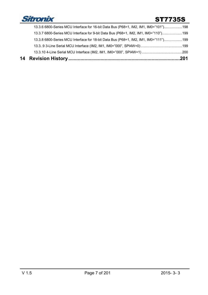
13.3.6 6800-Series MCU Interface for 16-bit Data Bus (P68=1, IM2, IM1, IM0=”101”)..................198
13.3.7 6800-Series MCU Interface for 9-bit Data Bus (P68=1, IM2, IM1, IM0=”110”)....................199
13.3.8 6800-Series MCU Interface for 18-bit Data Bus (P68=1, IM2, IM1, IM0=”111”)..................199
13.3..9 3-Line Serial MCU Interface (IM2, IM1, IM0=”000”, SPI4W=0) .........................................199
13.3.10 4-Line Serial MCU Interface (IM2, IM1, IM0=”000”, SPI4W=1) ........................................200
14 Revision History...................................................................................201
V 1.5 Page 7 of 201 2015- 3- 3
�
ST7735S
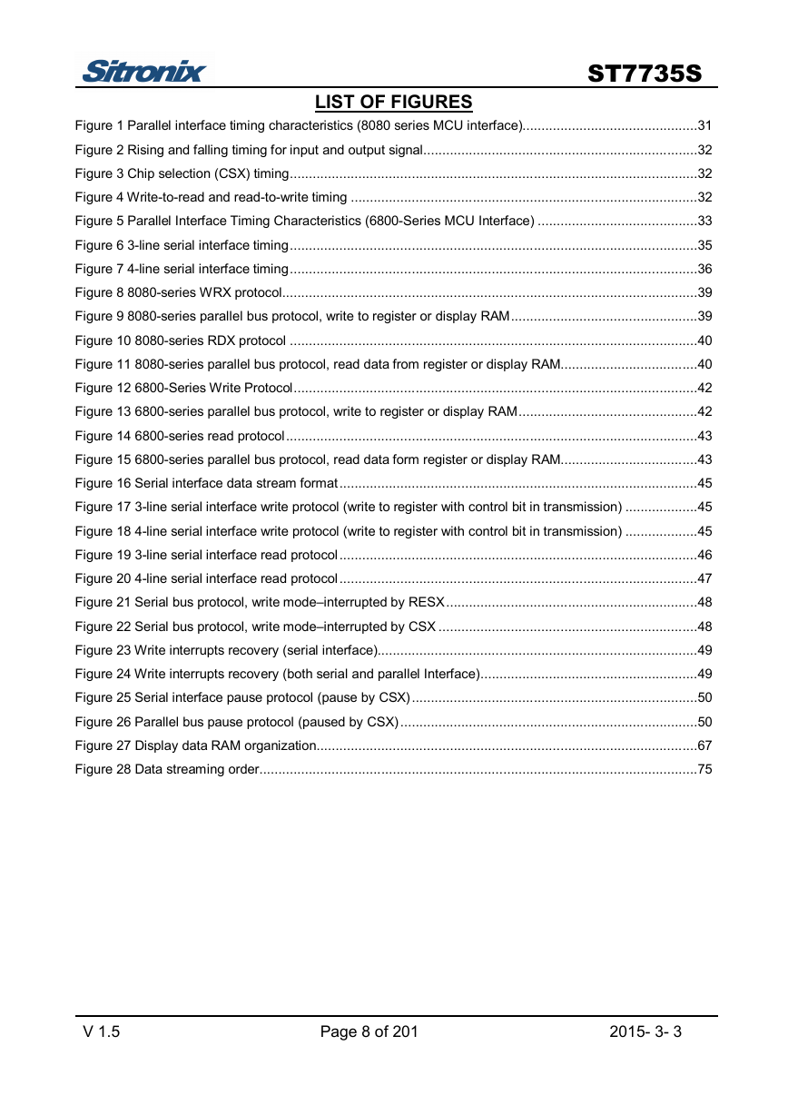
LIST OF FIGURES
Figure 1 Parallel interface timing characteristics (8080 series MCU interface)..............................................31
Figure 2 Rising and falling timing for input and output signal........................................................................32
Figure 3 Chip selection (CSX) timing...........................................................................................................32
Figure 4 Write-to-read and read-to-write timing ...........................................................................................32
Figure 5 Parallel Interface Timing Characteristics (6800-Series MCU Interface) ..........................................33
Figure 6 3-line serial interface timing...........................................................................................................35
Figure 7 4-line serial interface timing...........................................................................................................36
Figure 8 8080-series WRX protocol.............................................................................................................39
Figure 9 8080-series parallel bus protocol, write to register or display RAM.................................................39
Figure 10 8080-series RDX protocol ...........................................................................................................40
Figure 11 8080-series parallel bus protocol, read data from register or display RAM....................................40
Figure 12 6800-Series Write Protocol..........................................................................................................42
Figure 13 6800-series parallel bus protocol, write to register or display RAM...............................................42
Figure 14 6800-series read protocol............................................................................................................43
Figure 15 6800-series parallel bus protocol, read data form register or display RAM....................................43
Figure 16 Serial interface data stream format..............................................................................................45
Figure 17 3-line serial interface write protocol (write to register with control bit in transmission) ...................45
Figure 18 4-line serial interface write protocol (write to register with control bit in transmission) ...................45
Figure 19 3-line serial interface read protocol..............................................................................................46
Figure 20 4-line serial interface read protocol..............................................................................................47
Figure 21 Serial bus protocol, write mode–interrupted by RESX..................................................................48
Figure 22 Serial bus protocol, write mode–interrupted by CSX ....................................................................48
Figure 23 Write interrupts recovery (serial interface)....................................................................................49
Figure 24 Write interrupts recovery (both serial and parallel Interface).........................................................49
Figure 25 Serial interface pause protocol (pause by CSX)...........................................................................50
Figure 26 Parallel bus pause protocol (paused by CSX) ..............................................................................50
Figure 27 Display data RAM organization....................................................................................................67
Figure 28 Data streaming order...................................................................................................................75
V 1.5 Page 8 of 201 2015- 3- 3
�




 2023年江西萍乡中考道德与法治真题及答案.doc
 2012年重庆南川中考生物真题及答案.doc
 2013年江西师范大学地理学综合及文艺理论基础考研真题.doc
 2020年四川甘孜小升初语文真题及答案I卷.doc
 2020年注册岩土工程师专业基础考试真题及答案.doc
 2023-2024学年福建省厦门市九年级上学期数学月考试题及答案.doc
 2021-2022学年辽宁省沈阳市大东区九年级上学期语文期末试题及答案.doc
 2022-2023学年北京东城区初三第一学期物理期末试卷及答案.doc
 2018上半年江西教师资格初中地理学科知识与教学能力真题及答案.doc
 2012年河北国家公务员申论考试真题及答案-省级.doc
 2020-2021学年江苏省扬州市江都区邵樊片九年级上学期数学第一次质量检测试题及答案.doc
 2022下半年黑龙江教师资格证中学综合素质真题及答案.doc