�4 +��BECKH=J�H
��,-�
�4��9!�5-672 �-
1�56)��)61�� /71,-
��,-�
��,-�
+�,-
6D=�� O�K B�H ?D��IE�C JDA �-�5�.6 �4 +��BECKH=J�H�
6� �FJE�E�A JDA KIA �B JDA �4 +��BECKH=J�H� F�A=IA HA=@ �LAH JDEI 1�IJ=��=JE�� /KE@A
=�@ JDA ?�HHAIF��@E�C )+ IAHL� 1�IJ=��=JE�� /KE@A >AB�HA KIE�C JDA I�BJM=HA� )BJAH
HA=@E�C JDA 1�IJ=��=JE�� /KE@A� =�M=OI F�=?A JDEI 1�IJ=��=JE�� /KE@A E� = I=BA F�=?A�
1* ��)� �!���& �. ��'� � �--
2HE�JA@ E� �=F=�
6DEI 1�IJ=��=JE�� /KE@A KIAI HA?O?�A@ F=FAH�
5FA?EBE?=JE��I IK>�A?J J� ?D=�CA MEJD�KJ ��JE?A�
0-), �..1+- � 6��;� *�,/ �)47��7+01 6��;� ����&!��
.
�
Safety Instructions
(Always read these instructions before using the equipment.)
Do not attempt to install, operate, maintain or inspect the servo amplifier and servo motor until you have read
through this Installation Guide, and appended documents carefully and can use the equipment correctly. Do
not use the servo amplifier and servo motor until you have a full knowledge of the equipment, safety
information and instructions.
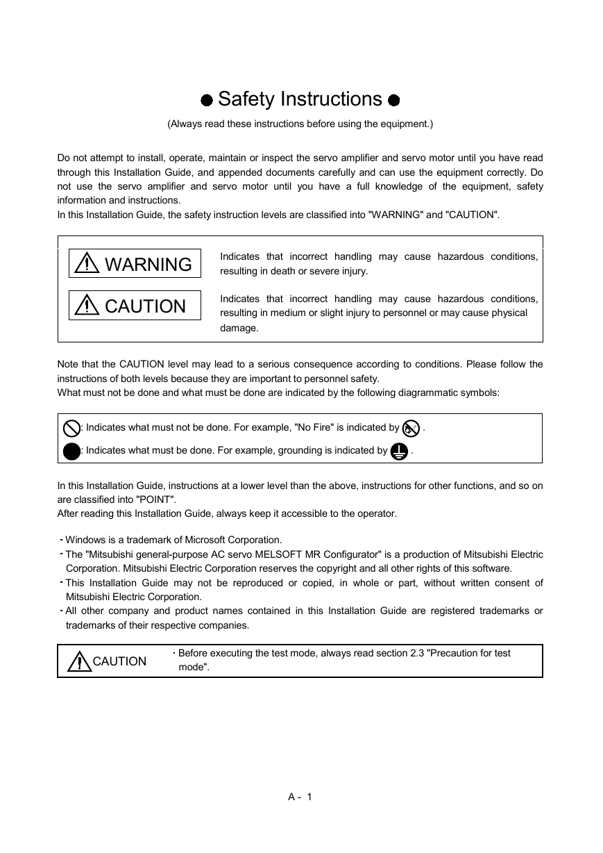
In this Installation Guide, the safety instruction levels are classified into "WARNING" and "CAUTION".
WARNING Indicates that incorrect handling may cause hazardous conditions,
resulting in death or severe injury.
CAUTION
Indicates that incorrect handling may cause hazardous conditions,
resulting in medium or slight injury to personnel or may cause physical
damage.
Note that the CAUTION level may lead to a serious consequence according to conditions. Please follow the
instructions of both levels because they are important to personnel safety.
What must not be done and what must be done are indicated by the following diagrammatic symbols:
: Indicates what must not be done. For example, "No Fire" is indicated by
: Indicates what must be done. For example, grounding is indicated by
.
.
In this Installation Guide, instructions at a lower level than the above, instructions for other functions, and so on
are classified into "POINT".
After reading this Installation Guide, always keep it accessible to the operator.
Windows is a trademark of Microsoft Corporation.
The "Mitsubishi general-purpose AC servo MELSOFT MR Configurator" is a production of Mitsubishi Electric
Corporation. Mitsubishi Electric Corporation reserves the copyright and all other rights of this software.
This Installation Guide may not be reproduced or copied, in whole or part, without written consent of
Mitsubishi Electric Corporation.
All other company and product names contained in this Installation Guide are registered trademarks or
trademarks of their respective companies.
CAUTION
Before executing the test mode, always read section 2.3 "Precaution for test
mode".
A - 1
�
MEMO
A - 2
�
CONTENTS
1. INTRODUCTION
1 - 1 to 1 -12
1.1 Specifications ........................................................................................................................................... 1 - 1
1.2 System configuration ............................................................................................................................... 1 - 3
1.2.1 Components ...................................................................................................................................... 1 - 3
1.2.2 Configuration ..................................................................................................................................... 1 - 4
1.3 Basic terms............................................................................................................................................... 1 - 6
1.4 Installation procedure............................................................................................................................... 1 - 7
1.5 New hardware detection wizard .............................................................................................................1 -10
2. HOW TO USE THE SOFTWARE
2 - 1 to 2 -10
2.1 Operation.................................................................................................................................................. 2 - 1
2.1.1 Start-up .............................................................................................................................................. 2 - 1
2.1.2 Project................................................................................................................................................ 2 - 1
2.2 Commands and display windows............................................................................................................ 2 - 3
2.3 Precautions for test mode........................................................................................................................ 2 - 6
2.4 Simple language for program operation.................................................................................................. 2 - 8
2.4.1 Language........................................................................................................................................... 2 - 8
2.4.2 Program example.............................................................................................................................. 2 - 9
2.4.3 Instruction .......................................................................................................................................... 2 - 9
3. TROUBLESHOOTING
3 - 1 to 3 - 4
1
�
MEMO
2
�
1. INTRODUCTION
1. INTRODUCTION
1.1 Specifications
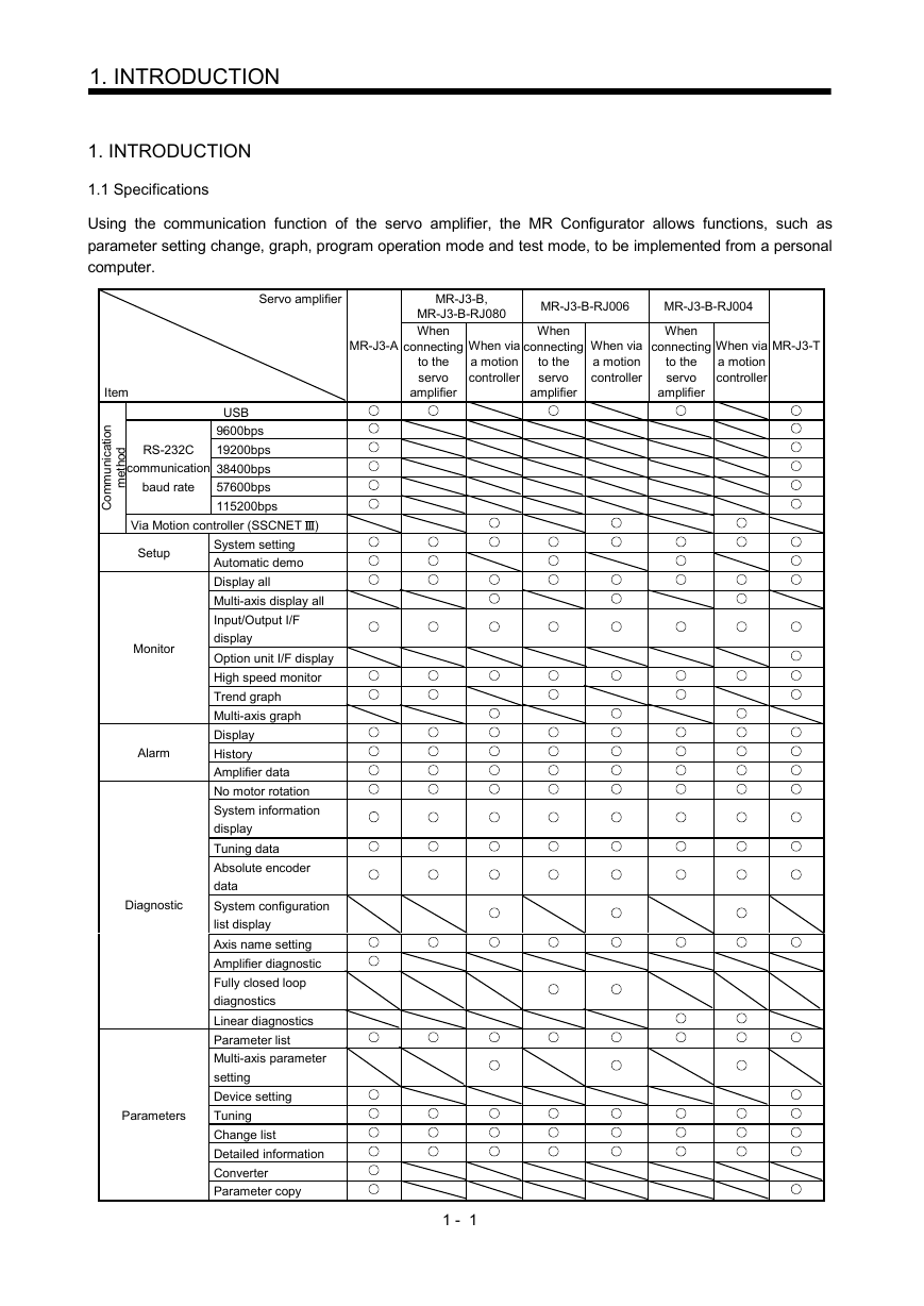
Using the communication function of the servo amplifier, the MR Configurator allows functions, such as
parameter setting change, graph, program operation mode and test mode, to be implemented from a personal
computer.
MR-J3-B,
MR-J3-B-RJ080
When
MR-J3-B-RJ006
When
connecting
to the
servo
amplifier
When via
a motion
controller
connecting
to the
servo
amplifier
When via
a motion
controller
MR-J3-B-RJ004
When
connecting
to the
servo
amplifier
When via
a motion
controller
MR-J3-T
Servo amplifier
MR-J3-A
Item
i
n
o
i
t
a
c
n
u
m
m
o
C
d
o
h
t
e
m
RS-232C
communication
baud rate
USB
9600bps
19200bps
38400bps
57600bps
115200bps
Via Motion controller (SSCNET
)
Setup
Monitor
Alarm
Diagnostic
Parameters
System setting
Automatic demo
Display all
Multi-axis display all
Input/Output I/F
display
Option unit I/F display
High speed monitor
Trend graph
Multi-axis graph
Display
History
Amplifier data
No motor rotation
System information
display
Tuning data
Absolute encoder
data
System configuration
list display
Axis name setting
Amplifier diagnostic
Fully closed loop
diagnostics
Linear diagnostics
Parameter list
Multi-axis parameter
setting
Device setting
Tuning
Change list
Detailed information
Converter
Parameter copy
1 - 1
�
MR-J3-B,
MR-J3-B-RJ080
When
MR-J3-B-RJ006
When
connecting
to the
servo
amplifier
When via
a motion
controller
connecting
to the
servo
amplifier
When via
a motion
controller
MR-J3-B-RJ004
When
connecting
to the
servo
amplifier
When via
a motion
controller
MR-J3-T
1. INTRODUCTION
Servo amplifier
MR-J3-A
Item
Test
Advanced-function
Point data
Help
Jog
Positioning
Operation w/o motor
Forced output
Program operation
mode
Single-step Feed
Machine analyzer
Gain search
Machine simulation
Robust disturbance
compensating
Advanced Gain search
Point table
MR Configuration Help
Product information
1 - 2
�
1. INTRODUCTION
1.2 System configuration
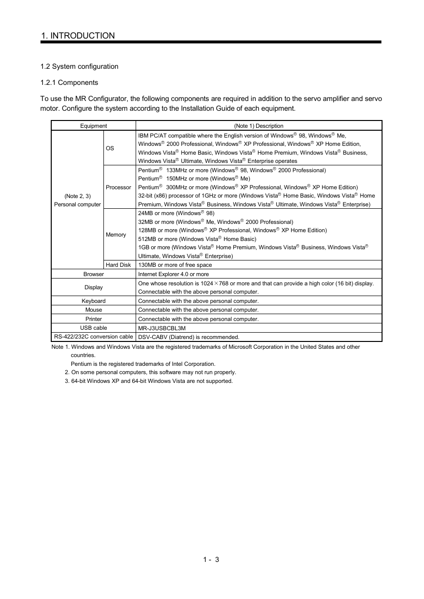
1.2.1 Components
To use the MR Configurator, the following components are required in addition to the servo amplifier and servo
motor. Configure the system according to the Installation Guide of each equipment.
Equipment
OS
Processor
(Note 2, 3)
Personal computer
Memory
Hard Disk
Browser
Display
Keyboard
Mouse
Printer
USB cable
(Note 1) Description
IBM PC/AT compatible where the English version of Windows R 98, Windows R Me,
Windows R 2000 Professional, Windows R XP Professional, Windows R XP Home Edition,
Windows Vista R Home Basic, Windows Vista R Home Premium, Windows Vista R Business,
Windows Vista R Ultimate, Windows Vista R Enterprise operates
Pentium R 133MHz or more (Windows R 98, Windows R 2000 Professional)
Pentium R 150MHz or more (Windows R Me)
Pentium R 300MHz or more (Windows R XP Professional, Windows R XP Home Edition)
32-bit (x86) processor of 1GHz or more (Windows Vista R Home Basic, Windows Vista R Home
Premium, Windows Vista R Business, Windows Vista R Ultimate, Windows Vista R Enterprise)
24MB or more (Windows R 98)
32MB or more (Windows R Me, Windows R 2000 Professional)
128MB or more (Windows R XP Professional, Windows R XP Home Edition)
512MB or more (Windows Vista R Home Basic)
1GB or more (Windows Vista R Home Premium, Windows Vista R Business, Windows Vista R
Ultimate, Windows Vista R Enterprise)
130MB or more of free space
Internet Explorer 4.0 or more
One whose resolution is 1024 768 or more and that can provide a high color (16 bit) display.
Connectable with the above personal computer.
Connectable with the above personal computer.
Connectable with the above personal computer.
Connectable with the above personal computer.
MR-J3USBCBL3M
RS-422/232C conversion cable DSV-CABV (Diatrend) is recommended.
Note 1. Windows and Windows Vista are the registered trademarks of Microsoft Corporation in the United States and other
countries.
Pentium is the registered trademarks of Intel Corporation.
2. On some personal computers, this software may not run properly.
3. 64-bit Windows XP and 64-bit Windows Vista are not supported.
1 - 3
�





 2023年江西萍乡中考道德与法治真题及答案.doc
 2012年重庆南川中考生物真题及答案.doc
 2013年江西师范大学地理学综合及文艺理论基础考研真题.doc
 2020年四川甘孜小升初语文真题及答案I卷.doc
 2020年注册岩土工程师专业基础考试真题及答案.doc
 2023-2024学年福建省厦门市九年级上学期数学月考试题及答案.doc
 2021-2022学年辽宁省沈阳市大东区九年级上学期语文期末试题及答案.doc
 2022-2023学年北京东城区初三第一学期物理期末试卷及答案.doc
 2018上半年江西教师资格初中地理学科知识与教学能力真题及答案.doc
 2012年河北国家公务员申论考试真题及答案-省级.doc
 2020-2021学年江苏省扬州市江都区邵樊片九年级上学期数学第一次质量检测试题及答案.doc
 2022下半年黑龙江教师资格证中学综合素质真题及答案.doc