Phased Array System Toolbox
Design and simulate phased array signal processing systems
Phased Array System Toolbox™ provides algorithms and tools for the design, simulation, and analysis of phased
array signal processing systems. These capabilities are provided as MATLAB® functions and MATLAB System
objects™. The system toolbox includes algorithms for waveform generation, beamforming, direction of arrival
estimation, target detection, and space-time adaptive processing.
The system toolbox lets you build monostatic, bistatic, and multistatic architectures for a variety of array
geometries. You can model these architectures on stationary or moving platforms. Array analysis and
visualization apps help you evaluate spatial, spectral, and temporal performance. The system toolbox lets you
model an end-to-end phased array system or use individual algorithms to process acquired data.
Key Features
▪ Monostatic and multistatic radar system modeling, including point targets, free-space propagation, surface
clutter, and barrage jammer
▪ Modeling of sensor arrays and subarrays with arbitrary geometries
▪ Polarization and platform motion specification for arrays and targets
▪ Synthesis and analysis of continuous and pulsed waveforms
▪ Broadband and narrowband digital beamforming, including MVDR/Capon, LCMV, time delay, Frost, and
subband phase shift
▪ Direction of arrival algorithms, including monopulse, beamscan, MVDR, root MUSIC, and ESPRIT
▪ Algorithms for TVG, pulse compression, coherent and noncoherent integration, CFAR processing, plotting
ROC curves, and estimating range and Doppler
▪ Space-time adaptive processing (STAP), including sample matrix inversion (SMI), and angle-Doppler
response visualization
The system toolbox includes examples that provide a starting point for implementing user-defined phased array
systems.
Phased Array Design and Analysis
Phased Array System Toolbox enables you to model and analyze the behavior of common array geometries and
user-defined array geometries. Common array geometries include:
▪ Uniform linear array (ULA)
▪ Uniform rectangular array (URA)
▪ Conformal array
You can define your own array geometry by specifying the number of elements, the element spacing, and each
element’s position and orientation in 3D space. The individual element response and radiation pattern can be
isotropic, cosine shaded, or specified by your own 3D pattern. Your response and radiation pattern can be either
described by an ideal analytic function or defined from measured data. You can apply shading (tapering) across
the entire array.
You can also define multiple element patterns in an array to model an inhomogeneous array.
1
�
With the system toolbox, you can model common antenna and microphone elements. In a custom antenna or
microphone, you can specify wideband, frequency-dependent patterns. You can also specify polarization in
polarization-capable antenna elements, such as Dipole or custom antennas.
The system toolbox provides tools to visualize and analyze the radiation pattern of individual elements or of the
whole array in aggregate. The visualization can be inspected in rectangular, spherical, and u/v space. With the
tools, you can measure or visualize:
▪ Array geometry
▪ Array gain
▪ Array response
▪ Delay between elements
▪ Steering vector
▪ Element response
Three-dimensional beam pattern for a 10 x 10 uniform rectangular array.
Waveform Design and Analysis
Phased Array System Toolbox supports waveform design and analysis for many common waveforms, including:
▪ Constant frequency (PCW)
▪ Linear frequency modulation (LFM)
2
�
▪ Stepped FM
▪ Frequency modulation constant waveform (FMCW)
▪ Phased coded waveforms
The system toolbox provides a number of configurable parameters for each waveform, such as pulse repetition
frequency (PRF), sample rate, pulse duration, and bandwidth. You can also design waveforms with staggered PRFs
to address blind-speed problems in moving target indicator (MTI) systems. Waveform envelopes can be either
rectangular or Gaussian weighted.
The system toolbox also provides apps and functions to visualize your waveform design, such as the ambiguity
function (AF). The AF provides insight into the waveform characteristic in terms of range resolution, Doppler
resolution, and the coupling between range and Doppler. It also provides the ideal matched-filter response.
Ambiguity function for a stepped FM waveform.
Transmitter and Receiver Modeling
Phased Array System Toolbox supports a generalized framework for modeling the physical transmission of a
waveform, its propagation through the environment, and its ultimate reception. This framework allows for
monostatic and bistatic system models. In addition, you can model array elements as part of a platform whose
dynamics (initial position and velocity) are user-defined. You can deploy transmitter elements and receiver
elements either on a common platform for monostatic modeling or on separate platforms for bistatic modeling.
You can also model stationary system geometries by specifying a zero-velocity vector.
Transmitter Modeling
The system toolbox provides tools to model transmitter behavior by specifying parameters such as:
▪ Gain
▪ Peak power
▪ Loss factor
▪ Platform motion
3
�
Receiver Modeling
You can also model the reception of a signal at the receiver array to accommodate a variety of situations. You can
control the receiver array’s behavior using the following attributes:
▪ Narrowband or broadband model
▪ Far-field or near-field model
▪ Array shading
▪ Platform motion
After a signal has been received across the array elements, you can configure the receiver front-end model
parameters such as:
▪ Gain
▪ Loss factor
▪ Noise bandwidth
▪ Noise figure
▪ Reference temperature
You can also configure receiver models for either coherent or noncoherent processing.
Target and Environment Modeling
Target Modeling
You can model targets as point reflectors, which are principally defined by the radar cross section (RCS) or the
RCS matrix if polarization is considered. Phased Array System Toolbox target models support the following target
types:
▪ Nonfluctuating RCS models (Swerling 0 or 5)
▪ Fluctuating RCS models (Swerling 1–4)
With the system toolbox you can model more complex, distributed targets by creating a collection of distributed
point reflectors. You can also model target motion by specifying the appropriate dynamics, such as initial position
and velocity.
Environment Modeling
The system toolbox includes free-space environment models that simulate one-way or two-way propagation
delays. It models both time delay and phase shift incurred during propagation. One-way propagation is useful for
modeling bistatic systems. Two-way propagation enables you to model monostatic systems. You can model
user-specified complex models with MATLAB algorithms. Alternatively, you can integrate third-party and
proprietary environment models with the system toolbox’s environment model.
The system toolbox also provides a barrage-jammer model to generate a wideband interference signal with
user-specified radiated power. You can use multiple jammers to model complex electromagnetic environments.
The system toolbox offers a constant gamma clutter model you can use to generate surface clutter from land or
sea. The surface is divided into small patches during the simulation, and the responses from patches are assembled
at the end to form the clutter echo. You can accelerate the clutter simulation using GPUs (requires Parallel
Computing Toolbox™).
4
�
Spatial Signal Processing
Digital Beamforming
Beamforming is a fundamental spatial signal processing operation of a phased array system. Phased Array System
Toolbox supports 1D and 2D beamforming techniques, as well as conventional and adaptive beamforming
techniques.
The system toolbox provides the Capon algorithm, a common adaptive beamformer for suppressing interference,
and the linearly constrained minimum variance (LCMV) beamformer, for avoiding situations where self-nulling
can occur. For broadband signals, the system toolbox offers adaptive algorithms such as the Frost and time delay
LCMV beamformers. You can also use subband processing as an alternative to time delays for broadband signals.
The system toolbox supports the following digital beamforming techniques:
▪ Narrowband
Narrowband, including conventional (phase shift), MVDR (Capon), and LCMV
▪ Broadband
Broadband, including Frost, time delay, time delay LCMV, and subband phase shift
Direction of Arrival Estimation
Estimating the direction of arrival (DOA) of incident signals is a fundamental spatial signal processing operation.
For various array geometries, the system toolbox provides several processing techniques for estimating DOA.
For uniform linear arrays, it provides:
▪ Sum and difference monopulse
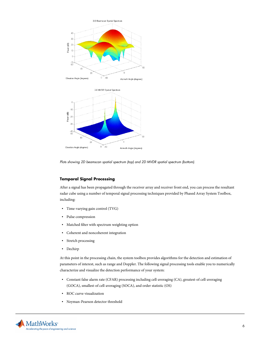
▪ Beamscan
▪ MVDR (Capon)
▪ High-resolution techniques, including ESPRIT, beamspace ESPRIT, root MUSIC, root WSF
For uniform rectangular arrays, it provides:
▪ Sum and difference monopulse
▪ Beamscan
▪ MVDR (Capon)
For conformal arrays, it provides:
▪ Beamscan
▪ MVDR (Capon)
When using high-resolution DOA techniques, you can use either the Akaike information criterion (AIC) or the
minimum description length (MDL) criterion to estimate the number of signals.
5
�
Plots showing 2D beamscan spatial spectrum (top) and 2D MVDR spatial spectrum (bottom).
Temporal Signal Processing
After a signal has been propagated through the receiver array and receiver front end, you can process the resultant
radar cube using a number of temporal signal processing techniques provided by Phased Array System Toolbox,
including:
▪ Time-varying gain control (TVG)
▪ Pulse compression
▪ Matched filter with spectrum weighting option
▪ Coherent and noncoherent integration
▪ Stretch processing
▪ Dechirp
At this point in the processing chain, the system toolbox provides algorithms for the detection and estimation of
parameters of interest, such as range and Doppler. The following signal processing tools enable you to numerically
characterize and visualize the detection performance of your system:
▪ Constant false alarm rate (CFAR) processing including cell-averaging (CA), greatest-of cell-averaging
(GOCA), smallest-of cell-averaging (SOCA), and order statistic (OS)
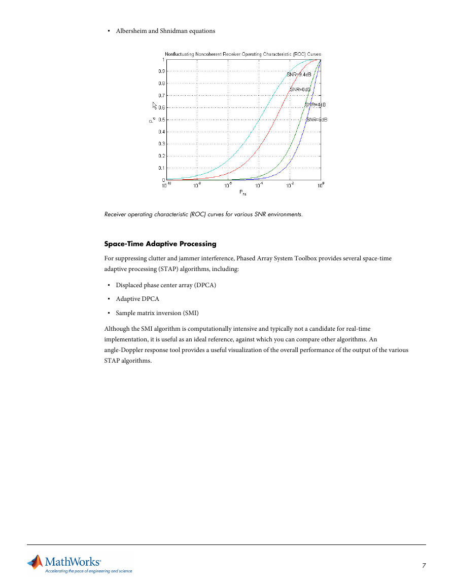
▪ ROC curve visualization
▪ Neyman-Pearson detector threshold
6
�
▪ Albersheim and Shnidman equations
Receiver operating characteristic (ROC) curves for various SNR environments.
Space-Time Adaptive Processing
For suppressing clutter and jammer interference, Phased Array System Toolbox provides several space-time
adaptive processing (STAP) algorithms, including:
▪ Displaced phase center array (DPCA)
▪ Adaptive DPCA
▪ Sample matrix inversion (SMI)
Although the SMI algorithm is computationally intensive and typically not a candidate for real-time
implementation, it is useful as an ideal reference, against which you can compare other algorithms. An
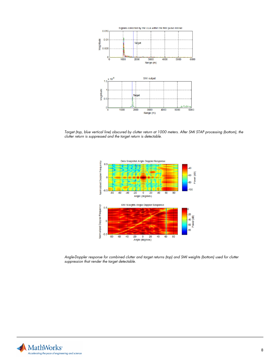
angle-Doppler response tool provides a useful visualization of the overall performance of the output of the various
STAP algorithms.
7
�
Target (top, blue vertical line) obscured by clutter return at 1000 meters. After SMI STAP processing (bottom), the
clutter return is suppressed and the target return is detectable.
Angle-Doppler response for combined clutter and target returns (top) and SMI weights (bottom) used for clutter
suppression that render the target detectable.
8
�



 2023年江西萍乡中考道德与法治真题及答案.doc
 2012年重庆南川中考生物真题及答案.doc
 2013年江西师范大学地理学综合及文艺理论基础考研真题.doc
 2020年四川甘孜小升初语文真题及答案I卷.doc
 2020年注册岩土工程师专业基础考试真题及答案.doc
 2023-2024学年福建省厦门市九年级上学期数学月考试题及答案.doc
 2021-2022学年辽宁省沈阳市大东区九年级上学期语文期末试题及答案.doc
 2022-2023学年北京东城区初三第一学期物理期末试卷及答案.doc
 2018上半年江西教师资格初中地理学科知识与教学能力真题及答案.doc
 2012年河北国家公务员申论考试真题及答案-省级.doc
 2020-2021学年江苏省扬州市江都区邵樊片九年级上学期数学第一次质量检测试题及答案.doc
 2022下半年黑龙江教师资格证中学综合素质真题及答案.doc