Network Working Group
Request for Comments: 4137
Category: Informational
J. Vollbrecht
Meetinghouse Data Communications
P. Eronen
Nokia
N. Petroni
University of Maryland
Y. Ohba
TARI
August 2005
State Machines for Extensible Authentication Protocol (EAP)
Peer and Authenticator
Status of This Memo
This memo provides information for the Internet community. It does not specify an Internet standard of any
kind. Distribution of this memo is unlimited.
Copyright Notice
Copyright (C) The Internet Society (2005).
Abstract
This document describes a set of state machines for Extensible Authentication Protocol (EAP) peer, EAP
stand-alone authenticator (non-pass-through), EAP backend authenticator (for use on Authentication,
Authorization, and Accounting (AAA) servers), and EAP full authenticator (for both local and pass-through).
This set of state machines shows how EAP can be implemented to support deployment in either a
peer/authenticator or peer/authenticator/AAA Server environment. The peer and stand-alone authenticator
machines are illustrative of how the EAP protocol defined in RFC 3748 may be implemented. The backend
and full/pass-through authenticators illustrate how EAP/AAA protocol support defined in RFC 3579 may be
implemented. Where there are differences, RFC 3748 and RFC 3579 are authoritative.
The state machines are based on the EAP "Switch" model. This model includes events and actions for the
interaction between the EAP Switch and EAP methods. A brief description of the EAP "Switch" model is
given in the Introduction section.
The state machine and associated model are informative only. Implementations may achieve the same results
using different methods.
Vollbrecht, et al.
Informational
[Page 1]
�
RFC 4137
EAP State Machines
August 2005
Table of Contents
1. Introduction: The EAP Switch Model...........................................................................................................3
2. Specification of Requirements.......................................................................................................................4
3. Notational Conventions Used in State Diagrams ......................................................................................... 4
3.1. Notational Specifics ............................................................................................................................. 4
3.2. State Machine Symbols ........................................................................................................................ 6
3.3. Document Authority ............................................................................................................................. 7
4. Peer State Machine ...................................................................................................................................... 8
4.1. Interface between Peer State Machine and Lower Layer ..................................................................... 9
4.2. Interface between Peer State Machine and Methods .......................................................................... 11
4.3. Peer State Machine Local Variables ................................................................................................... 12
4.4. Peer State Machine Procedures .......................................................................................................... 13
4.5. Peer State Machine States .................................................................................................................. 14
5. Stand-Alone Authenticator State Machine ................................................................................................ 16
5.1. Interface between Stand-Alone Authenticator State Machine and Lower Layer ............................... 17
5.2. Interface between Stand-Alone Authenticator State Machine and Methods ...................................... 19
5.3. Stand-Alone Authenticator State Machine Local Variables ............................................................... 20
5.4. EAP Stand-Alone Authenticator Procedures ..................................................................................... 21
5.5. EAP Stand-Alone Authenticator States .............................................................................................. 23
6. EAP Backend Authenticator ...................................................................................................................... 25
6.1. Interface between Backend Authenticator State Machine and Lower Layer ..................................... 27
6.2. Interface between Backend Authenticator State Machine .................................................................. 28
6.3. Backend Authenticator State Machine Local Variables ..................................................................... 28
6.4. EAP Backend Authenticator Procedures ............................................................................................ 29
6.5. EAP Backend Authenticator States .................................................................................................... 29
7. EAP Full Authenticator ............................................................................................................................. 30
7.1. Interface between Full Authenticator State Machine and Lower Layers ........................................... 31
7.2. Interface between Full Authenticator State Machine and Methods .....................................................33
7.3. Full Authenticator State Machine Local Variables ............................................................................. 33
7.4. EAP Full Authenticator Procedures ................................................................................................... 34
7.5. EAP Full Authenticator States ........................................................................................................... 34
8. Implementation Considerations ................................................................................................................. 36
8.1 Robustness ............................................................................................................................................ 36
8.2 Method/Method and Method/Lower-Layer Interfaces ......................................................................... 36
8.3 Peer State Machine Interoperability with Deployed Implementatios.....................................................36
9. Security Considerations ............................................................................................................................. 37
10. Acknowledgements .................................................................................................................................. 38
11. References ................................................................................................................................................ 38
11.1. Normative References ....................................................................................................................... 38
11.2. Informative References ...................................................................................................................... 38
Appendix. ASCII Versions of State Diagrams ............................................................................................... 39
A.1. EAP Peer State Machine (Figure 3) .................................................................................................. 39
A.2. EAP Stand-Alone Authenticator State Machine (Figure 4) .............................................................. 42
A.3. EAP Backend Authenticator State Machine (Figure 5)...................................................................... 45
A.4. EAP Full Authenticator State Machine (Figures 6 and 7).................................................................. 48
Vollbrecht, et al.
Informational
[Page 2]
�
RFC 4137
EAP State Machines
August 2005
1. Introduction: The EAP Switch Model
This document offers a proposed state machine for RFCs [RFC3748] and [RFC3579]. There are state
machines for the peer, the stand-alone authenticator, a backend authenticator, and a full/pass-through
authenticator. Accompanying each state machine diagram is a description of the variables, the functions, and
the states in the diagram. Whenever possible, the same notation has been used in each of the state machines.
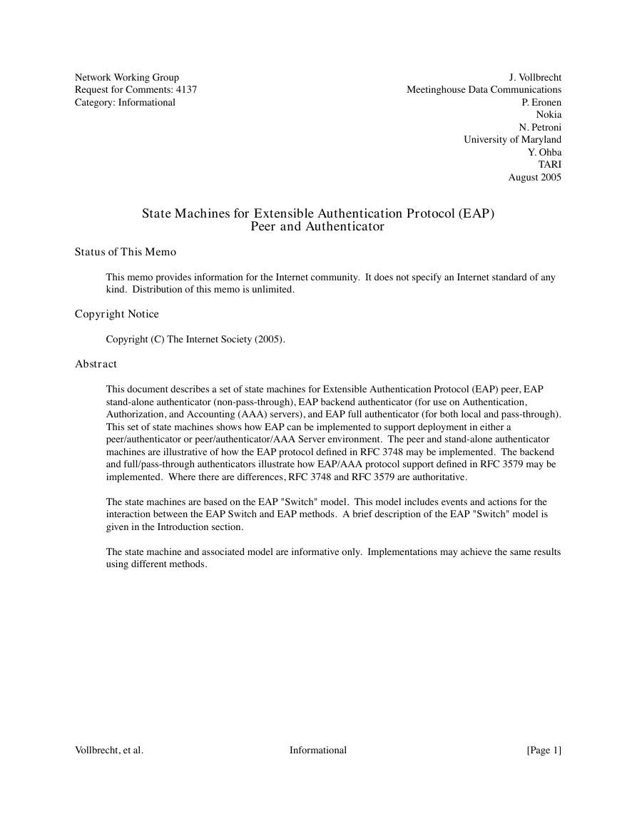
An EAP authentication consists of one or more EAP methods in sequence followed by an EAP Success or
EAP Failure sent from the authenticator to the peer. The EAP switches control negotiation of EAP methods
and sequences of methods.
Peer
Method
Peer
Authenticator
Auth
Method
\
\
Peer
EAP
Switch
<-----|---------->
|
|
|
|
|
|
/
/
Auth
EAP
Switch
Figure 1: EAP Switch Model
At both the peer and authenticator, one or more EAP methods exist. The EAP switches select which
methods each is willing to use, and negotiate between themselves to pick a method or sequence of methods.
Note that the methods may also have state machines. The details of these are outside the scope of this paper.
Peer | Authenticator
/
|
|
Peer |
EAP -|-----> EAP
Auth
/
Switch |
|
|
|
Switch
\
Local
Method
| Backend
|
|
|
|
|
|
\ pass-through |
|
/
/
Backend
--> EAP
Server
Figure 2: EAP Pass-Through Model
The Full/Pass-Through state machine allows an NAS or edge device to pass EAP Response messages to a
backend server where the authentication method resides. This paper includes a state machine for the EAP
authenticator that supports both local and pass-through methods as well as a state machine for the backend
authenticator existing at the AAA server. A simple stand-alone authenticator is also provided to show a
basic, non-pass-through authenticator’s behavior.
Vollbrecht, et al.
Informational
[Page 3]
�
RFC 4137
EAP State Machines
August 2005
This document describes a set of state machines that can manage EAP authentication from the peer to an
EAP method on the authenticator or from the peer through the authenticator pass-through method to the EAP
method on the backend EAP server.
Some environments where EAP is used, such as PPP, may support peer-to-peer operation. That is, both
parties act as peers and authenticators at the same time, in two simultaneous and independent EAP
conversations. In this case, the implementation at each node has to perform demultiplexing of incoming
EAP packets. EAP packets with code set to Response are delivered to the authenticator state machine, and
EAP packets with code set to Request, Success, or Failure are delivered to the peer state machine.
The state diagrams presented in this document have been coordinated with the diagrams in [1X-2004]. The
format of the diagrams is adapted from the format therein. The interface between the state machines defined
here and the IEEE 802.1X-2004 state machines is also explained in Appendix F of [1X-2004].
2. Specification of Requirements
In this document, several words are used to signify the requirements of the specification. These words are
often capitalized. The key words "MUST", "MUST NOT", "REQUIRED", "SHALL", "SHALL NOT",
"SHOULD", "SHOULD NOT", "RECOMMENDED", "MAY", and "OPTIONAL" are to be interpreted as
described in [RFC2119].
3. Notational Conventions Used in State Diagrams
3.1. Notational Specifics
The following state diagrams have been completed based on the conventions specified in [1X-2004], section
8.2.1. The complete text is reproduced here:
State diagrams are used to represent the operation of the protocol by a number of cooperating state
machines, each comprising a group of connected, mutually exclusive states. Only one state of each
machine can be active at any giv en time.
Each state is represented in the state diagram as a rectangular box, divided into two parts by a
horizontal line. The upper part contains the state identifier, written in uppercase letters. The lower
part contains any procedures that are executed upon entry to the state.
All permissible transitions between states are represented by arrows, the arrowhead denoting the
direction of the possible transition. Labels attached to arrows denote the condition(s) that must be
met in order for the transition to take place. All conditions are expressions that evaluate to TRUE or
FALSE; if a condition evaluates to TRUE, then the condition is met. The label UCT denotes an
unconditional transition (i.e., UCT always evaluates to TRUE). A transition that is global in nature
(i.e., a transition that occurs from any of the possible states if the condition attached to the arrow is
met) is denoted by an open arrow; i.e., no specific state is identified as the origin of the transition.
When the condition associated with a global transition is met, it supersedes all other exit conditions
including UCT. The special global condition BEGIN supersedes all other global conditions, and once
asserted it remains asserted until all state blocks have executed to the point that variable assignments
and other consequences of their execution remain unchanged.
Vollbrecht, et al.
Informational
[Page 4]
�
RFC 4137
EAP State Machines
August 2005
On entry to a state, the procedures defined for the state (if any) are executed exactly once, in the order
that they appear on the page. Each action is deemed to be atomic; i.e., execution of a procedure
completes before the next sequential procedure starts to execute. No procedures execute outside a
state block. The procedures in only one state block execute at a time, even if the conditions for
execution of state blocks in different state machines are satisfied, and all procedures in an executing
state block complete execution before the transition to and execution of any other state block occurs.
That is, the execution of any state block appears to be atomic with respect to the execution of any
other state block, and the transition condition to that state from the previous state is TRUE when
execution commences. The order of execution of state blocks in different state machines is undefined
except as constrained by their transition conditions. A variable that is set to a particular value in a
state block retains this value until a subsequent state block executes a procedure that modifies the
value.
On completion of all the procedures within a state, all exit conditions for the state (including all
conditions associated with global transitions) are evaluated continuously until one of the conditions is
met. The label ELSE denotes a transition that occurs if none of the other conditions for transitions
from the state are met (i.e., ELSE evaluates to TRUE if all other possible exit conditions from the
state evaluate to FALSE). Where two or more exit conditions with the same level of precedence
become TRUE simultaneously, the choice as to which exit condition causes the state transition to take
place is arbitrary.
Where it is necessary to split a state machine description across more than one diagram, a transition
between two states that appear on different diagrams is represented by an exit arrow drawn with
dashed lines, plus a reference to the diagram that contains the destination state. Similarly, dashed
arrows and a dashed state box are used on the destination diagram to show the transition to the
destination state. In a state machine that has been split in this way, any global transitions that can
cause entry to states defined in one of the diagrams are deemed potential exit conditions for all the
states of the state machine, regardless of which diagram the state boxes appear in.
Should a conflict exist between the interpretation of a state diagram and either the corresponding
global transition tables or the textual description associated with the state machine, the state diagram
takes precedence. The interpretation of the special symbols and operators used in the state diagrams
is as defined in Section 3.2; these symbols and operators are derived from the notation of the C++
programming language, ISO/IEC 14882. If a boolean variable is described in this clause as being set,
it has or is assigned the value TRUE; if it is described as being reset or clear, it has the value FALSE.
In addition to the above notation, there are a couple of clarifications specific to this document. First, all
boolean variables are initialized to FALSE before the state machine execution begins. Second, the following
notational shorthand is specific to this document:
= | | ...
Execution of a statement of this form will result in having a value of exactly one of the
expressions. The logic for which of those expressions gets executed is outside of the state machine
and could be environmental, configurable, or based on another state machine, such as that of the
method.
Vollbrecht, et al.
Informational
[Page 5]
�
RFC 4137
EAP State Machines
August 2005
3.2. State Machine Symbols
( )
;
=
!
&&
||
Used to force the precedence of operators in Boolean expressions and to delimit the argument(s) of
actions within state boxes.
Used as a terminating delimiter for actions within state boxes. If a state box contains multiple
actions, the order of execution follows the normal English language conventions for reading text.
Assignment action. The value of the expression to the right of the operator is assigned to the variable
to the left of the operator. If this operator is used to define multiple assignments (e.g., a = b = X), the
action causes the value of the expression following the right-most assignment operator to be assigned
to all the variables that appear to the left of the right-most assignment operator.
Logical NOT operator.
Logical AND operator.
Logical OR operator.
if...then...
Conditional action. If the Boolean expression following the "if" evaluates to TRUE, then the action
following the "then" is executed.
{ statement 1, ... statement N }
Compound statement. Braces are used to group statements that are executed together as if they were
a single statement.
!=
Inequality. Evaluates to TRUE if the expression to the left of the operator is not equal in value to the
expression to the right.
Vollbrecht, et al.
Informational
[Page 6]
�
RFC 4137
EAP State Machines
August 2005
==
>
<=
++
+
&
Equality. Evaluates to TRUE if the expression to the left of the operator is equal in value to the
expression to the right.
Greater than. Evaluates to TRUE if the value of the expression to the left of the operator is greater
than the value of the expression to the right.
Less than or equal to. Evaluates to TRUE if the value of the expression to the left of the operator is
either less than or equal to the value of the expression to the right.
Increment the preceding integer operator by 1.
Arithmetic addition operator.
Bitwise AND operator.
3.3. Document Authority
Should a conflict exist between the interpretation of a state diagram and either the corresponding global
transition tables or the textual description associated with the state machine, the state diagram takes
precedence. When a discrepancy occurs between any part of this document (text or diagram) and any of the
related documents ([RFC3748], [RFC3579], etc.), the latter (the other document) is considered authoritative
and takes precedence.
Vollbrecht, et al.
Informational
[Page 7]
�
RFC 4137
EAP State Machines
August 2005
4. Peer State Machine
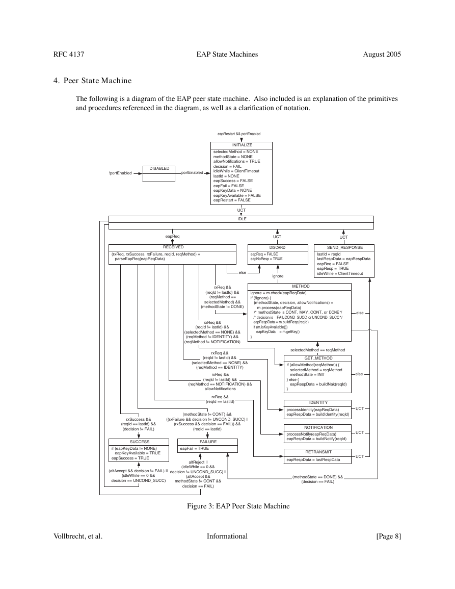
The following is a diagram of the EAP peer state machine. Also included is an explanation of the primitives
and procedures referenced in the diagram, as well as a clarification of notation.
!portEnabled
DISABLED
portEnabled
eapRestart && portEnabled
INITIALIZE
selectedMethod = NONE
methodState = NONE
allowNotifications = TRUE
decision = FAIL
idleWhile = ClientTimeout
lastId = NONE
eapSuccess = FALSE
eapFail = FALSE
eapKeyData = NONE
eapKeyAvailable = FALSE
eapRestart = FALSE
UCT
IDLE
eapReq
RECEIVED
(rxReq, rxSuccess, rxFailure, reqId, reqMethod) =
parseEapReq(eapReqData)
UCT
DISCARD
eapReq = FALSE
eapNoResp = TRUE
else
ignore
UCT
SEND_RESPONSE
lastId = reqId
lastRespData = eapRespData
eapReq = FALSE
eapResp = TRUE
idleWhile = ClientTimeout
rxReq &&
(reqId != lastId) &&
(reqMethod ==
selectedMethod) &&
(methodState != DONE)
rxReq &&
(reqId != lastId) &&
(selectedMethod == NONE) &&
(reqMethod != IDENTITY) &&
(reqMethod != NOTIFICATION)
METHOD
METHOD
ignore = m.check(eapReqData)
intCheck = m.integrityCheck(eapReqData)
if (!ignore) {
if (intCheck) {
(methodState, decision, allowNotifications) =
m.process(eapReqData)
m.process(eapReqData)
methodState = CONT | MAY_CONT | DONE
/* methodState is CONT, MAY_CONT, or DONE */
decision = FAIL | COND_SUCC | UNCOND_SUCC
/* decision is FAIL, COND_SUCC, or UNCOND_SUCC */
allowNotifications = TRUE | FALSE
eapRespData = m.buildResp(reqId)
eapRespData = m.buildResp(reqId)
if (m.isKeyAvailable())
eapKeyData = NONE | m.getKey()
eapKeyData
}
}
= m.getKey()
else
else
rxReq &&
(reqId != lastId) &&
(selectedMethod == NONE) &&
(reqMethod == IDENTITY)
rxReq &&
(reqId != lastId) &&
(reqMethod == NOTIFICATION) &&
allowNotifications
rxReq &&
(reqId == lastId)
rxSuccess &&
(reqId == lastId) &&
(decision != FAIL)
(methodState != CONT) &&
((rxFailure && decision != UNCOND_SUCC) ||
(rxSuccess && decision == FAIL)) &&
(reqId == lastId)
SUCCESS
if (eapKeyData != NONE)
eapKeyAvailable = TRUE
eapSuccess = TRUE
(altAccept && decision != FAIL) ||
(idleWhile == 0 &&
decision == UNCOND_SUCC)
FAILURE
eapFail = TRUE
altReject ||
(idleWhile == 0 &&
decision != UNCOND_SUCC) ||
(altAccept &&
methodState != CONT &&
decision == FAIL)
selectedMethod == reqMethod
GET_METHOD
if (allowMethod(reqMethod)) {
selectedMethod = reqMethod
methodState = INIT
} else {
eapRespData = buildNak(reqId)
}
IDENTITY
processIdentity(eapReqData)
eapRespData = buildIdentity(reqId)
UCT
NOTIFICATION
processNotify(eapReqData)
eapRespData = buildNotify(reqId)
RETRANSMIT
eapRespData = lastRespData
UCT
UCT
(methodState == DONE) &&
(decision == FAIL)
Figure 3: EAP Peer State Machine
Vollbrecht, et al.
Informational
[Page 8]
�


 2023年江西萍乡中考道德与法治真题及答案.doc
 2012年重庆南川中考生物真题及答案.doc
 2013年江西师范大学地理学综合及文艺理论基础考研真题.doc
 2020年四川甘孜小升初语文真题及答案I卷.doc
 2020年注册岩土工程师专业基础考试真题及答案.doc
 2023-2024学年福建省厦门市九年级上学期数学月考试题及答案.doc
 2021-2022学年辽宁省沈阳市大东区九年级上学期语文期末试题及答案.doc
 2022-2023学年北京东城区初三第一学期物理期末试卷及答案.doc
 2018上半年江西教师资格初中地理学科知识与教学能力真题及答案.doc
 2012年河北国家公务员申论考试真题及答案-省级.doc
 2020-2021学年江苏省扬州市江都区邵樊片九年级上学期数学第一次质量检测试题及答案.doc
 2022下半年黑龙江教师资格证中学综合素质真题及答案.doc