OEM7® Commands and Logs Reference Manual
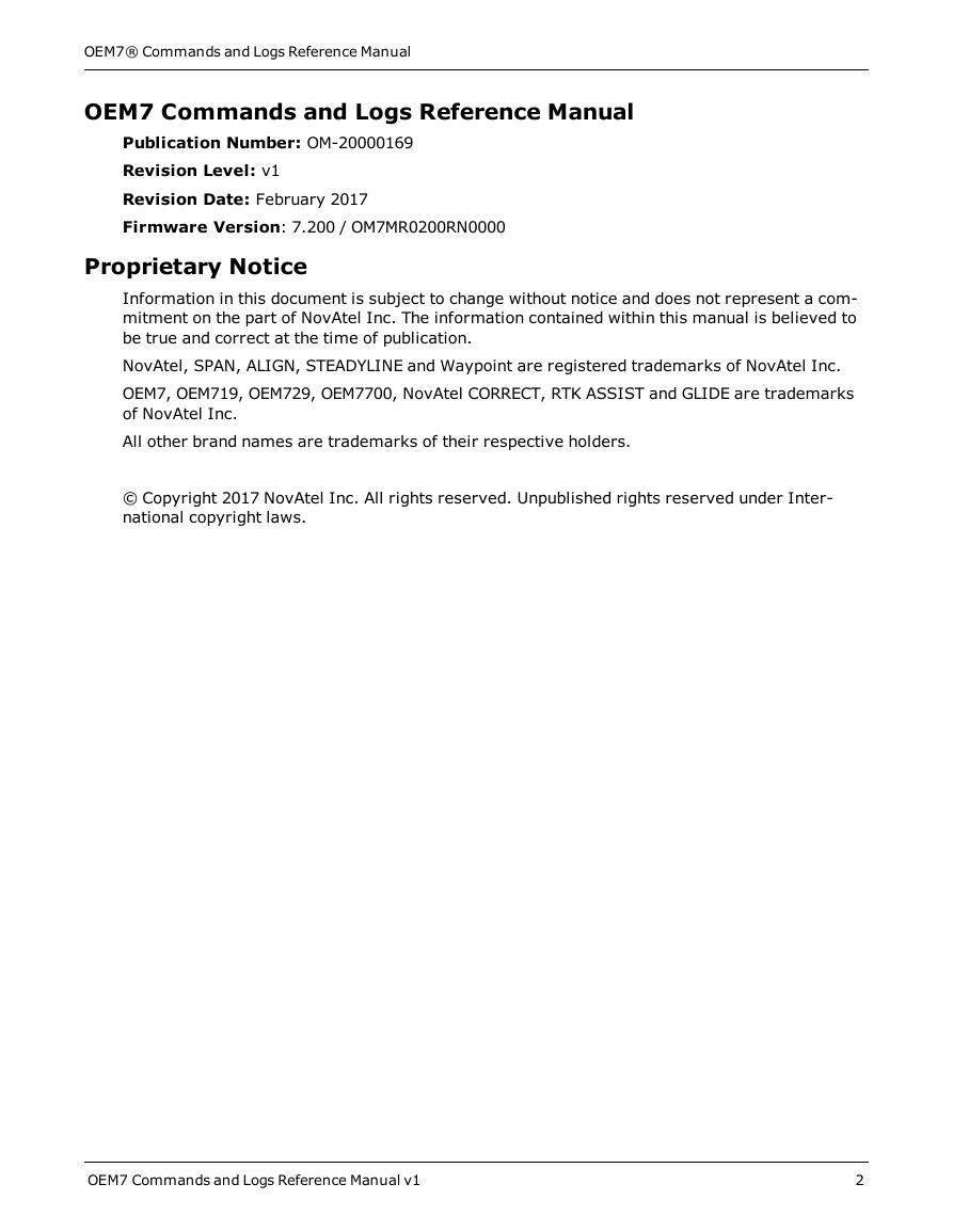
OEM7 Commands and Logs Reference Manual
Proprietary Notice
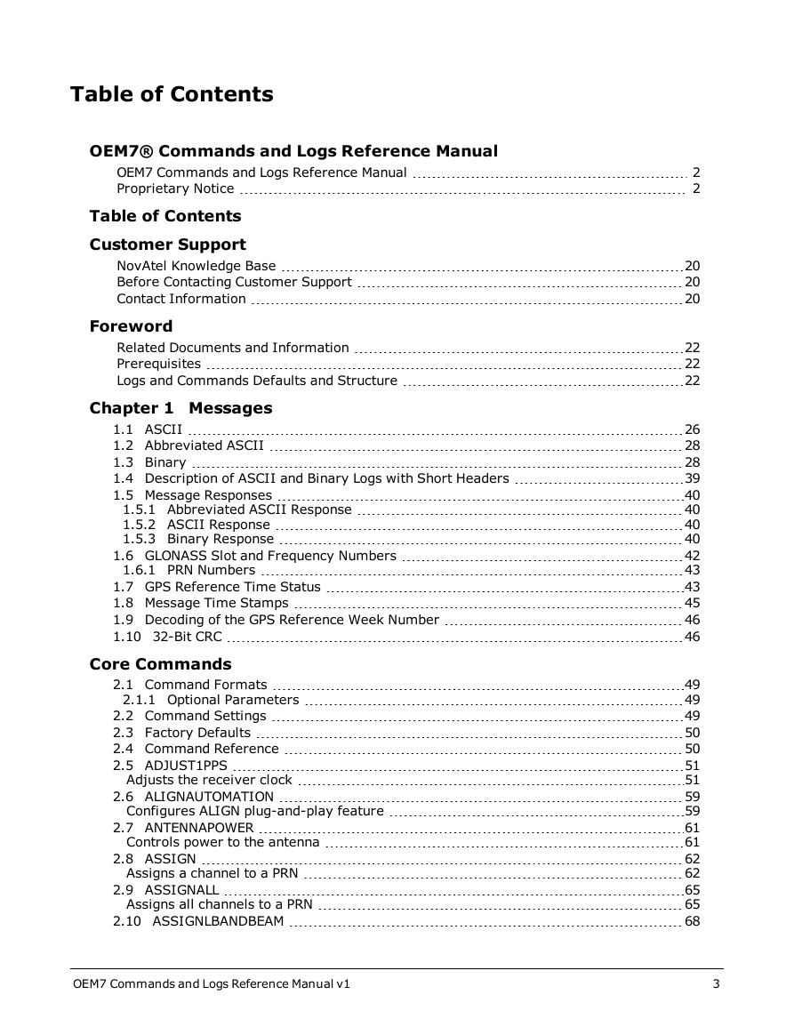
Table of Contents
Customer Support
NovAtel Knowledge Base
Before Contacting Customer Support
Contact Information
Foreword
Related Documents and Information
Prerequisites
Logs and Commands Defaults and Structure
Chapter 1 Messages
1.1 ASCII
1.2 Abbreviated ASCII
1.3 Binary
1.4 Description of ASCII and Binary Logs with Short Headers
1.5 Message Responses
1.5.1 Abbreviated ASCII Response
1.5.2 ASCII Response
1.5.3 Binary Response
1.6 GLONASS Slot and Frequency Numbers
1.6.1 PRN Numbers
1.7 GPS Reference Time Status
1.8 Message Time Stamps
1.9 Decoding of the GPS Reference Week Number
1.10 32-Bit CRC
Core Commands
2.1 Command Formats
2.1.1 Optional Parameters
2.2 Command Settings
2.3 Factory Defaults
2.4 Command Reference
2.5 ADJUST1PPS
Adjusts the receiver clock
2.6 ALIGNAUTOMATION
Configures ALIGN plug-and-play feature
2.7 ANTENNAPOWER
Controls power to the antenna
2.8 ASSIGN
Assigns a channel to a PRN
2.9 ASSIGNALL
Assigns all channels to a PRN
2.10 ASSIGNLBANDBEAM
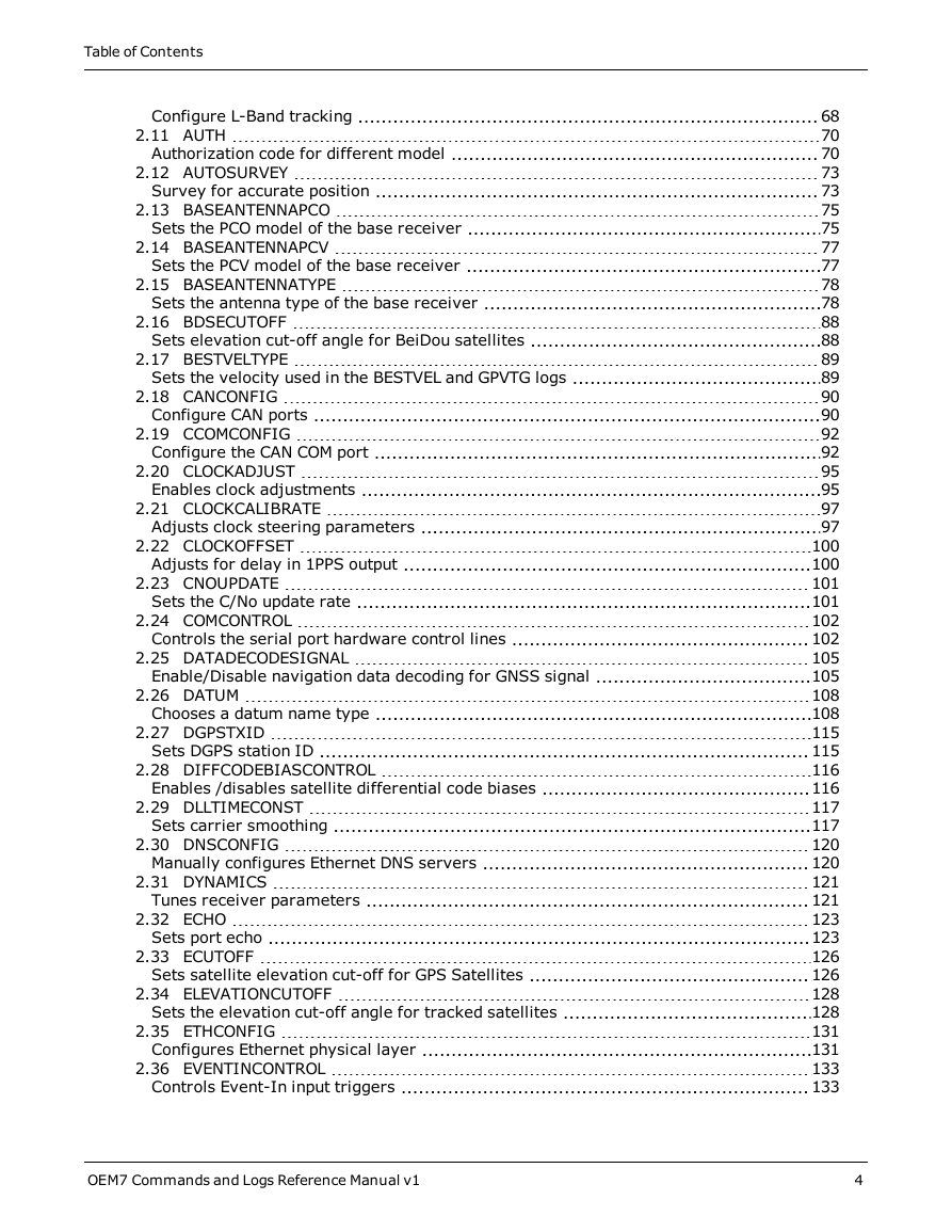
Configure L-Band tracking
2.11 AUTH
Authorization code for different model
2.12 AUTOSURVEY
Survey for accurate position
2.13 BASEANTENNAPCO
Sets the PCO model of the base receiver
2.14 BASEANTENNAPCV
Sets the PCV model of the base receiver
2.15 BASEANTENNATYPE
Sets the antenna type of the base receiver
2.16 BDSECUTOFF
Sets elevation cut-off angle for BeiDou satellites
2.17 BESTVELTYPE
Sets the velocity used in the BESTVEL and GPVTG logs
2.18 CANCONFIG
Configure CAN ports
2.19 CCOMCONFIG
Configure the CAN COM port
2.20 CLOCKADJUST
Enables clock adjustments
2.21 CLOCKCALIBRATE
Adjusts clock steering parameters
2.22 CLOCKOFFSET
Adjusts for delay in 1PPS output
2.23 CNOUPDATE
Sets the C/No update rate
2.24 COMCONTROL
Controls the serial port hardware control lines
2.25 DATADECODESIGNAL
Enable/Disable navigation data decoding for GNSS signal
2.26 DATUM
Chooses a datum name type
2.27 DGPSTXID
Sets DGPS station ID
2.28 DIFFCODEBIASCONTROL
Enables /disables satellite differential code biases
2.29 DLLTIMECONST
Sets carrier smoothing
2.30 DNSCONFIG
Manually configures Ethernet DNS servers
2.31 DYNAMICS
Tunes receiver parameters
2.32 ECHO
Sets port echo
2.33 ECUTOFF
Sets satellite elevation cut-off for GPS Satellites
2.34 ELEVATIONCUTOFF
Sets the elevation cut-off angle for tracked satellites
2.35 ETHCONFIG
Configures Ethernet physical layer
2.36 EVENTINCONTROL
Controls Event-In input triggers
2.37 EVENTOUTCONTROL
Control Event-Out properties
2.38 EXTERNALCLOCK
Sets external clock parameters
2.39 FIX
Constrains to fixed height or position
2.40 FIXPOSDATUM
Sets position in a specified datum
2.41 FORCEGLOL2CODE
Forces receiver to track GLONASS satellite L2 P or L2 C/A code
2.42 FORCEGPSL2CODE
Forces receiver to track GPS satellite L2 P or L2C code
2.43 FREQUENCYOUT
Sets output pulse train available on VARF
2.44 FRESET
Clears selected data from NVM and reset
2.45 GALECUTOFF
Sets elevation cut-off angle for Galileo satellites
2.46 GENERATEALIGNCORRECTIONS
Configure ALIGN Master
2.47 GENERATEDIFFCORRECTIONS
Sends a preconfigured set of differential corrections
2.48 GENERATERTKCORRECTIONS
Sends a preconfigured set of RTK corrections
2.49 GGAQUALITY
Customizes the GPGGA GPS quality indicator
2.50 GLIDEINITIALIZATIONPERIOD
Configures the GLIDE initialization period
2.51 GLOECUTOFF
Sets GLONASS satellite elevation cut-off
2.52 HDTOUTTHRESHOLD
Controls GPHDT log output
2.53 HEADINGOFFSET
Adds heading and pitch offset values
2.54 ICOMCONFIG
Configures IP virtual COM port
2.55 INTERFACEMODE
Sets receive or transmit modes for ports
2.55.1 SPAN Systems
2.56 IONOCONDITION
Sets ionospheric condition
2.57 IPCONFIG
Configures network IP settings
2.58 IPSERVICE
Configure availability of networks ports/services
2.59 ITBANDPASSCONFIG
Enable and configure bandpass filter on receiver
2.60 ITFRONTENDMODE
Configure the front end mode settings
2.61 ITINTERFERENCEDETECT
Enable and configure interference detection on receiver
2.62 ITPROGFILTCONFIG
Enable and configure filtering on the receiver
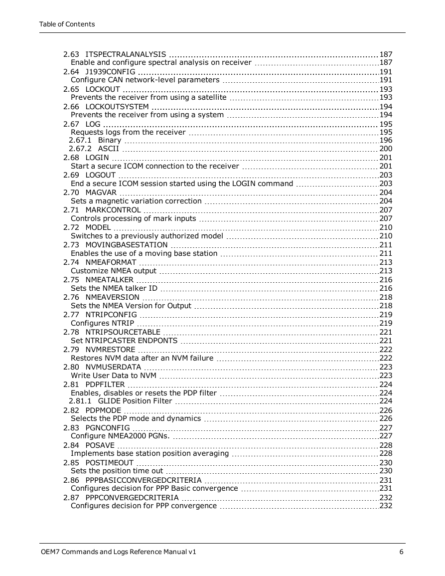
2.63 ITSPECTRALANALYSIS
Enable and configure spectral analysis on receiver
2.64 J1939CONFIG
Configure CAN network-level parameters
2.65 LOCKOUT
Prevents the receiver from using a satellite
2.66 LOCKOUTSYSTEM
Prevents the receiver from using a system
2.67 LOG
Requests logs from the receiver
2.67.1 Binary
2.67.2 ASCII
2.68 LOGIN
Start a secure ICOM connection to the receiver
2.69 LOGOUT
End a secure ICOM session started using the LOGIN command
2.70 MAGVAR
Sets a magnetic variation correction
2.71 MARKCONTROL
Controls processing of mark inputs
2.72 MODEL
Switches to a previously authorized model
2.73 MOVINGBASESTATION
Enables the use of a moving base station
2.74 NMEAFORMAT
Customize NMEA output
2.75 NMEATALKER
Sets the NMEA talker ID
2.76 NMEAVERSION
Sets the NMEA Version for Output
2.77 NTRIPCONFIG
Configures NTRIP
2.78 NTRIPSOURCETABLE
Set NTRIPCASTER ENDPONTS
2.79 NVMRESTORE
Restores NVM data after an NVM failure
2.80 NVMUSERDATA
Write User Data to NVM
2.81 PDPFILTER
Enables, disables or resets the PDP filter
2.81.1 GLIDE Position Filter
2.82 PDPMODE
Selects the PDP mode and dynamics
2.83 PGNCONFIG
Configure NMEA2000 PGNs.
2.84 POSAVE
Implements base station position averaging
2.85 POSTIMEOUT
Sets the position time out
2.86 PPPBASICCONVERGEDCRITERIA
Configures decision for PPP Basic convergence
2.87 PPPCONVERGEDCRITERIA
Configures decision for PPP convergence
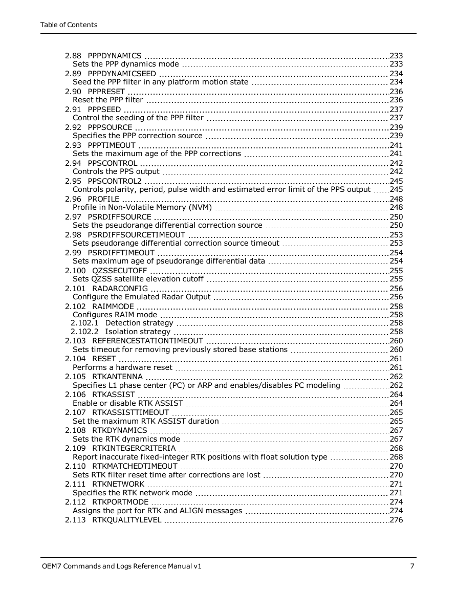
2.88 PPPDYNAMICS
Sets the PPP dynamics mode
2.89 PPPDYNAMICSEED
Seed the PPP filter in any platform motion state
2.90 PPPRESET
Reset the PPP filter
2.91 PPPSEED
Control the seeding of the PPP filter
2.92 PPPSOURCE
Specifies the PPP correction source
2.93 PPPTIMEOUT
Sets the maximum age of the PPP corrections
2.94 PPSCONTROL
Controls the PPS output
2.95 PPSCONTROL2
Controls polarity, period, pulse width and estimated error limit of the PPS output
2.96 PROFILE
Profile in Non-Volatile Memory (NVM)
2.97 PSRDIFFSOURCE
Sets the pseudorange differential correction source
2.98 PSRDIFFSOURCETIMEOUT
Sets pseudorange differential correction source timeout
2.99 PSRDIFFTIMEOUT
Sets maximum age of pseudorange differential data
2.100 QZSSECUTOFF
Sets QZSS satellite elevation cutoff
2.101 RADARCONFIG
Configure the Emulated Radar Output
2.102 RAIMMODE
Configures RAIM mode
2.102.1 Detection strategy
2.102.2 Isolation strategy
2.103 REFERENCESTATIONTIMEOUT
Sets timeout for removing previously stored base stations
2.104 RESET
Performs a hardware reset
2.105 RTKANTENNA
Specifies L1 phase center (PC) or ARP and enables/disables PC modeling
2.106 RTKASSIST
Enable or disable RTK ASSIST
2.107 RTKASSISTTIMEOUT
Set the maximum RTK ASSIST duration
2.108 RTKDYNAMICS
Sets the RTK dynamics mode
2.109 RTKINTEGERCRITERIA
Report inaccurate fixed-integer RTK positions with float solution type
2.110 RTKMATCHEDTIMEOUT
Sets RTK filter reset time after corrections are lost
2.111 RTKNETWORK
Specifies the RTK network mode
2.112 RTKPORTMODE
Assigns the port for RTK and ALIGN messages
2.113 RTKQUALITYLEVEL
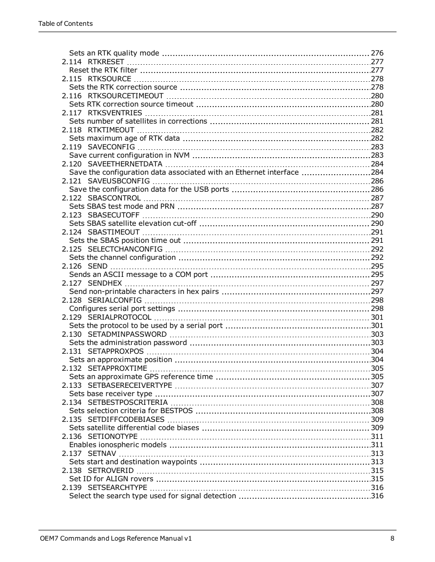
Sets an RTK quality mode
2.114 RTKRESET
Reset the RTK filter
2.115 RTKSOURCE
Sets the RTK correction source
2.116 RTKSOURCETIMEOUT
Sets RTK correction source timeout
2.117 RTKSVENTRIES
Sets number of satellites in corrections
2.118 RTKTIMEOUT
Sets maximum age of RTK data
2.119 SAVECONFIG
Save current configuration in NVM
2.120 SAVEETHERNETDATA
Save the configuration data associated with an Ethernet interface
2.121 SAVEUSBCONFIG
Save the configuration data for the USB ports
2.122 SBASCONTROL
Sets SBAS test mode and PRN
2.123 SBASECUTOFF
Sets SBAS satellite elevation cut-off
2.124 SBASTIMEOUT
Sets the SBAS position time out
2.125 SELECTCHANCONFIG
Sets the channel configuration
2.126 SEND
Sends an ASCII message to a COM port
2.127 SENDHEX
Send non-printable characters in hex pairs
2.128 SERIALCONFIG
Configures serial port settings
2.129 SERIALPROTOCOL
Sets the protocol to be used by a serial port
2.130 SETADMINPASSWORD
Sets the administration password
2.131 SETAPPROXPOS
Sets an approximate position
2.132 SETAPPROXTIME
Sets an approximate GPS reference time
2.133 SETBASERECEIVERTYPE
Sets base receiver type
2.134 SETBESTPOSCRITERIA
Sets selection criteria for BESTPOS
2.135 SETDIFFCODEBIASES
Sets satellite differential code biases
2.136 SETIONOTYPE
Enables ionospheric models
2.137 SETNAV
Sets start and destination waypoints
2.138 SETROVERID
Set ID for ALIGN rovers
2.139 SETSEARCHTYPE
Select the search type used for signal detection
2.140 SETTIMEBASE
Sets primary and backup systems for time base
2.141 SETTROPOMODEL
Sets Troposphere model
2.142 SETUTCLEAPSECONDS
Sets future leap seconds
2.143 SOFTLOADCOMMIT
Completes the SoftLoad process
2.144 SOFTLOADDATA
Sends firmware image data to the receiver for the SoftLoad process
2.145 SOFTLOADRESET
Initiates a new SoftLoad process
2.146 SOFTLOADSETUP
Sends configuration information to the receiver for the SoftLoad process
2.147 SOFTLOADSREC
Sends an S-Record to the receiver for the SoftLoad process
2.148 STATUSCONFIG
Configures RXSTATUSEVENT mask fields
2.149 STEADYLINE
Configures position mode matching
2.150 STEADYLINEDIFFERENTIALTIMEOUT
Sets how long the receiver will report RTK/PPP after corrections are lost
2.151 THISANTENNAPCO
Sets the PCO model of this receiver
2.152 THISANTENNAPCV
Sets the PCV model of this receiver
2.153 THISANTENNATYPE
Sets the antenna type of this receiver
2.154 TRACKSV
Overrides automatic satellite assignment criteria
2.155 TUNNELESCAPE
Breaks out of an established tunnel
2.156 UALCONTROL
Setup User Accuracy levels
2.157 UNASSIGN
Unassigns a previously assigned channel
2.158 UNASSIGNALL
Unassigns all previously assigned channels
2.159 UNDULATION
Chooses undulation
2.160 UNLOCKOUT
Reinstates a satellite in the solution
2.161 UNLOCKOUTALL
Reinstates all previously locked out satellites
2.162 UNLOCKOUTSYSTEM
Reinstates previously locked out system
2.163 UNLOG
Removes a log from logging control
2.163.1 Binary
2.163.2 ASCII
2.164 UNLOGALL
Removes all logs from logging control
2.165 USBCONFIG
Configure the USB ports
2.166 USERDATUM
Sets user customized datum
2.167 USEREXPDATUM
Set custom expanded datum
2.168 UTMZONE
Sets UTM parameters
Chapter 3 Logs
3.1 Log Types
3.1.1 Log Type Examples
3.2 Log Reference
3.3 ALIGNBSLNENU
ENU baselines using ALIGN
3.4 ALIGNBSLNXYZ
XYZ baselines using ALIGN
3.5 ALIGNDOP
Calculated DOP values
3.6 ALMANAC
Decoded GPS Almanac
3.7 AUTHCODES
List of authorization codes
3.8 AVEPOS
Position averaging
3.9 BDSALMANAC
Decoded BDS Almanac
3.10 BDSCLOCK
BeiDou time parameters
3.11 BDSEPHEMERIS
Decoded BDS ephemeris
3.12 BDSIONO
BeiDou Klobuchar ionosphere delay model
3.13 BDSRAWNAVSUBFRAME
Raw BeiDou subframe data
3.14 BESTPOS
Best position
3.15 BESTSATS
Satellites used in BESTPOS
3.16 BESTUTM
Best available UTM data
3.17 BESTVEL
Best available velocity data
3.18 BESTXYZ
Best available cartesian position and velocity
3.19 BSLNXYZ
RTK XYZ baseline
3.20 CHANCONFIGLIST
Channel configuration list
3.21 CLOCKMODEL
Current clock model status
3.22 CLOCKSTEERING
Clock steering status
3.23 ETHSTATUS
Current Ethernet status
3.24 GALALMANAC
Decoded Galileo Almanac
3.25 GALCLOCK
Galileo clock information
3.26 GALFNAVEPHEMERIS
Decoded Galileo FNAV Ephemeris
3.27 GALFNAVRAWPAGE
Raw Galileo FNAV page data
3.28 GALINAVEPHEMERIS
Decoded Galileo INAV Ephemeris
3.29 GALINAVRAWWORD
Raw Galileo INAV word data
3.30 GALIONO
Decoded Galileo ionospheric corrections
3.31 GLMLA
NMEA GLONASS Almanac data
3.32 GLOALMANAC
Decoded GLONASS Almanac
3.33 GLOCLOCK
GLONASS clock information
3.34 GLOEPHEMERIS
Decoded GLONASS ephemeris
3.35 GLORAWALM
Raw GLONASS Almanac data
3.36 GLORAWEPHEM
Raw GLONASS Ephemeris data
3.37 GLORAWFRAME
Raw GLONASS frame data
3.38 GLORAWSTRING
Raw GLONASS string
3.39 GPALM
Almanac data
3.40 GPGGA
GPS fix data and undulation
3.41 GPGGALONG
Fix data, extra precision and undulation
3.42 GPGLL
Geographic position
3.43 GPGRS
GPS range residuals for each satellite
3.44 GPGSA
GPS DOP and active satellites
3.45 GPGST
Pseudorange measurement noise statistics
3.46 GPGSV
GPS satellites in view
3.47 GPHDT
NMEA heading log
3.48 GPRMB
Navigation information
3.49 GPRMC
GPS specific information
3.50 GPSEPHEM
Decoded GPS ephemerides
3.51 GPVTG
Track made good and ground speed
3.52 GPZDA
UTC time and date
3.53 HEADING2
Heading information with multiple rovers
3.54 HEADINGRATE
Heading rate information
3.55 HEADINGSATS
Satellite used in heading solution
3.56 HWMONITOR
Monitor hardware levels
3.57 IONUTC
Ionospheric and UTC data
3.58 IPSTATS
IP statistics
3.59 IPSTATUS
Current network configuration status
3.60 ITBANDPASSBANK
Allowable band pass filter configurations
3.61 ITFILTTABLE
Filter configuration for each frequency
3.62 ITPROGFILTBANK
Allowable filter configurations
3.63 ITPSDFINAL
Processed power spectral density
3.64 J1939STATUS
Status of CAN J1939 Node
3.65 LBANDBEAMTABLE
List of L-Band beams
3.66 LBANDRAWFRAME
Raw L-Band frame data
3.67 LBANDTRACKSTAT
L-Band Beams status
3.68 LOGLIST
List of system logs
3.68.1 Binary
3.68.2 ASCII
3.69 MARK1COUNT, MARK2COUNT, MARK3COUNT and MARK4COUNT
Count for the Mark inputs
3.70 MARKPOS, MARK2POS, MARK3POS and MARK4POS
Position at time of mark input event
3.71 MARKTIME, MARK2TIME, MARK3TIME and MARK4TIME
Time of mark input event
3.72 MASTERPOS
Master Position using ALIGN
3.73 MATCHEDPOS
Matched RTK position
3.74 MATCHEDSATS
Satellites used in MATCHEDPOS solution
3.75 MATCHEDXYZ
Matched RTK Cartesian position
3.76 MODELFEATURES
States features available for current loaded model
3.77 NAVIGATE
User navigation data
3.78 NMEA Standard Logs
3.79 NOVATELXOBS
NovAtel proprietary RTK correction
3.80 NOVATELXREF
NovAtel proprietary reference station message for use in ALIGN
3.81 PASSCOM, PASSXCOM, PASSAUX, PASSUSB, PASSETH1, PASSICOM, PASSNCOM
Redirects data
3.82 PASSTHROUGH
Redirected data from all ports
3.83 PDPPOS
PDP filter position
3.84 PDPSATS
Satellites used in PDPPOS solution
3.85 PDPVEL
PDP filter velocity
3.86 PDPXYZ
PDP filter Cartesian position and velocity
3.87 PORTSTATS
Port statistics
3.88 PPPPOS
PPP filter position
3.89 PPPSATS
Satellites used in the PPPPOS solution
3.90 PROFILEINFO
Profile information in NVM
3.91 PSRDOP
Pseudorange DOP
3.92 PSRDOP2
Pseudorange DOP
3.93 PSRPOS
Pseudorange position
3.94 PSRSATS
Satellites used in PSRPOS solution
3.95 PSRVEL
Pseudorange velocity
3.96 PSRXYZ
Pseudorange Cartesian position and velocity
3.97 QZSSALMANAC
Decoded QZSS Almanac parameters
3.98 QZSSEPHEMERIS
Decoded QZSS parameters
3.99 QZSSIONUTC
QZSS ionospheric and time information
3.100 QZSSRAWALMANAC
Raw QZSS almanac data
3.101 QZSSRAWCNAVMESSAGE
Raw QZSS L2C and L5 CNAV message
3.102 QZSSRAWEPHEM
QZSS Raw ephemeris information
3.103 QZSSRAWSUBFRAME
Raw QZSS subframe data
3.104 RAIMSTATUS
RAIM status
3.105 RANGE
Satellite range information
3.106 RANGECMP
Compressed version of the RANGE log
3.107 RANGECMP2
Compressed version of the RANGE log
3.108 RANGECMP4
Highly compressed version of the RANGE log
3.109 RANGEGPSL1
L1 version of the RANGE log
3.110 RAWALM
Raw GPS Almanac data
3.111 RAWCNAVFRAME
Raw GPS CNAV frame data
3.112 RAWEPHEM
Raw GPS ephemeris
3.113 RAWGPSSUBFRAME
Raw GPS subframe data
3.114 RAWGPSWORD
Raw GPS navigation word
3.115 RAWSBASFRAME
Raw SBAS frame data
3.116 REFSTATION
Base station position and health
3.117 REFSTATIONINFO
Base Station position information
3.118 ROVERPOS
Position using ALIGN
3.119 RTCMV3 Standard Logs
3.119.1 RTCM1001-RTCM1004 GPS RTK Observables
3.119.2 RTCM1005 and RTCM1006 RTK Base Antenna Reference Point (ARP)
3.119.3 RTCM1007 and RTCM1008 Extended Antenna Descriptions
3.119.4 RTCM1009-RTCM1012 GLONASS RTK Observables
3.119.5 RTCM1019-RTCM1020 GPS and GLONASS Ephemerides
3.119.6 RTCM1070-RTCM1229 Multiple Signal Messages (MSM)
3.120 RTKASSISTSTATUS
RTK ASSIST status
3.121 RTKDOP
DOP values from the RTK fast filter
3.122 RTKDOP2
DOP values from the RTK low latency filter
3.123 RTKPOS
RTK low latency position data
3.124 RTKSATS
Satellites used in RTKPOS solution
3.125 RTKVEL
RTK velocity
3.126 RTKXYZ
RTK Cartesian position and velocity
3.127 RXCONFIG
Receiver configuration
3.128 RXSTATUS
Receiver status
3.129 RXSTATUSEVENT
Status event indicator
3.130 SAFEMODESTATUS
Safe Mode Status
3.131 SATVIS2
Satellite visibility
3.132 SATXYZ2
Satellite positions in ECEF Cartesian coordinates
3.133 SBAS0
Do not use for safety applications
3.134 SBAS1
PRN mask assignments
3.135 SBAS2
Fast correction slots 0-12
3.136 SBAS3
Fast corrections slots 13-25
3.137 SBAS4
Fast correction slots 26-38
3.138 SBAS5
Fast correction slots 39-50
3.139 SBAS6
Integrity message
3.140 SBAS7
Fast correction degradation
3.141 SBAS9
GEO navigation message
3.142 SBAS10
Degradation factor
3.143 SBAS12
SBAS network time and UTC
3.144 SBAS17
GEO Almanac message
3.145 SBAS18
IGP mask
3.146 SBAS24
Mixed fast/slow corrections
3.147 SBAS25
Long term slow satellite corrections
3.148 SBAS26
Ionospheric delay corrections
3.149 SBAS27
SBAS service message
3.150 SBAS32
Fast correction slots 0-10
3.151 SBAS33
Fast correction slots 11-21
3.152 SBAS34
Fast correction slots 22-32
3.153 SBAS35
Fast correction slots 33-43
3.154 SBAS45
Slow corrections
3.155 SBASALMANAC
SBAS Almanac collection
3.156 SOFTLOADSTATUS
Describes the status of the SoftLoad process
3.157 SOURCETABLE
NTRIP source table entries
3.158 TERRASTARINFO
TerraStar subscription information
3.159 TERRASTARSTATUS
TerraStar decoder and subscription status
3.160 TIME
Time data
3.161 TIMESYNC
Synchronize time between GNSS receivers
3.162 TRACKSTAT
Tracking status
3.163 UPTIME
Report the running time of the receiver
3.164 VALIDMODELS
Valid model information
3.165 VERIPOSINFO
Veripos subscription information
3.166 VERIPOSSTATUS
Veripos decoder and subscription status
3.167 VERSION
Version information
Chapter 4 SPAN Commands
4.1 ALIGNMENTMODE
Set the Alignment Mode
4.2 ASYNCHINSLOGGING
Enable Asynchronous INS Logs
4.3 CONNECTIMU
Connects an IMU to a Port
4.4 DUALANTENNAPORTCONFIG
Select Dual Antenna Source Port
4.5 EXTERNALPVAS
Enter PVA Update
4.6 HEAVEFILTER
Enables or Disables Heave Filtering
4.7 INPUTGIMBALANGLE
Input Gimbal Angles into the Receiver
4.8 INSCALIBRATE
Initiate calibration of the INS offsets
4.9 INSCOMMAND
INS Control Command
4.10 INSSEED
Enable or disable last known SPAN solution
4.11 INSTHRESHOLDS
Change the INS_HIGH_VARIANCE Threshold
4.12 INSZUPT
Request Zero Velocity Update
4.13 RELINSAUTOMATION
Enables Relative INS on the Rover
4.14 RELINSCONFIG
Configure Relative INS
4.15 SETALIGNMENTVEL
Set the Minimum Kinematic Alignment Velocity
4.16 SETHEAVEWINDOW
Set Heave Filter Length
4.17 SETIMUPORTPROTOCOL
Sets the Protocol Used for the IMU Serial Port
4.18 SETIMUSPECS
Specify Error Specifications and Data Rate
4.19 SETINITAZIMUTH
Set Initial Azimuth and Standard Deviation
4.20 SETINSPROFILE
Sets filter behavior depending on system environment
4.21 SETINSROTATION
Specifies rotational offsets between the IMU frame and other reference frames
4.22 SETINSTRANSLATION
Specifies translational offsets between the IMU frame and other reference frames
4.23 SETINSUPDATE
Enable/Disable INS Filter Updates
4.24 SETMAXALIGNMENTTIME
Set a Time Limit for Static Course Alignment
4.25 SETRELINSOUTPUTFRAME
Sets the Relative INS Output Frame
4.26 SETUPSENSOR
Add a new sensor object
4.27 SETWHEELPARAMETERS
Set Wheel Parameters
4.28 TAGNEXTMARK
Tags the Next Incoming Mark Event
4.29 TIMEDEVENTPULSE
Add a new camera event
4.30 WHEELVELOCITY
Wheel Velocity for INS Augmentation
Chapter 5 SPAN Logs
5.1 Logs with INS or GNSS Data
5.2 BESTGNSSPOS
Best GNSS Position
5.3 BESTGNSSVEL
Best Available GNSS Velocity Data
5.4 CORRIMUDATA
Corrected IMU Measurements
5.5 CORRIMUDATAS
Short Corrected IMU Measurements
5.6 DELAYEDHEAVE
Delayed Heave Filter
5.7 GIMBALLEDPVA
Display Gimballed Position
5.8 HEAVE
Heave Filter Log
5.9 IMURATECORRIMUS
Asynchronous Corrected IMU Data
5.10 IMURATEPVA
Asynchronous INS Position, Velocity and Attitude
5.11 IMURATEPVAS
Asynchronous INS Position, Velocity and Attitude
5.12 INSATT
INS Attitude
5.13 INSATTS
Short INS Attitude
5.14 INSATTX
Inertial Attitude – Extended
5.15 INSCALSTATUS
Offset calibration status
5.16 INSCONFIG
Determine required settings for post-processing or system analysis
5.17 INSPOS
INS Position
5.18 INSPOSS
Short INS Position
5.19 INSPOSX
Inertial Position – Extended
5.20 INSPVA
INS Position, Velocity and Attitude
5.21 INSPVAS
Short INS Position, Velocity and Attitude
5.22 INSPVAX
Inertial PVA – Extended
5.23 INSSPD
INS Speed
5.24 INSSPDS
Short INS Speed
5.25 INSSTDEV
INS PVA standard deviations
5.26 INSSTDEVS
Short INS PVA standard deviations
5.27 INSUPDATESTATUS
INS Update Status
5.28 INSVEL
INS Velocity
5.29 INSVELS
Short INS Velocity
5.30 INSVELX
Inertial Velocity – Extended
5.31 MARK1PVA, MARK2PVA, MARK3PVA and MARK4PVA
Position, Velocity and Attitude at Mark Input Event
5.32 PASHR
NMEA, Inertial Attitude Data
5.33 RAWIMU
Raw IMU Data
5.34 RAWIMUS
Short Raw IMU Data
5.35 RAWIMUSX
IMU Data Extended
5.36 RAWIMUX
IMU Data Extended
5.37 RELINSPVA
Relative INSPVA log
5.38 SYNCHEAVE
Synchronous Log Containing the Instantaneous Heave Value
5.39 SYNCRELINSPVA
Synchronous Relative INSPVA log
5.40 TAGGEDMARK1PVA, TAGGEDMARK2PVA, TAGGEDMARK3PVA and TAGGEDMARK4PVA
Position, Velocity and Attitude at a Tagged Mark Request
5.41 TIMEDWHEELDATA
Timed Wheel Data
5.42 TSS1
TSS1 Protocol for Heave, Roll and Pitch
5.43 VARIABLELEVERARM
Display Variable Lever Arm Details
5.44 WHEELSIZE
Wheel Size
Chapter 6 Responses




 2023年江西萍乡中考道德与法治真题及答案.doc
 2012年重庆南川中考生物真题及答案.doc
 2013年江西师范大学地理学综合及文艺理论基础考研真题.doc
 2020年四川甘孜小升初语文真题及答案I卷.doc
 2020年注册岩土工程师专业基础考试真题及答案.doc
 2023-2024学年福建省厦门市九年级上学期数学月考试题及答案.doc
 2021-2022学年辽宁省沈阳市大东区九年级上学期语文期末试题及答案.doc
 2022-2023学年北京东城区初三第一学期物理期末试卷及答案.doc
 2018上半年江西教师资格初中地理学科知识与教学能力真题及答案.doc
 2012年河北国家公务员申论考试真题及答案-省级.doc
 2020-2021学年江苏省扬州市江都区邵樊片九年级上学期数学第一次质量检测试题及答案.doc
 2022下半年黑龙江教师资格证中学综合素质真题及答案.doc