201
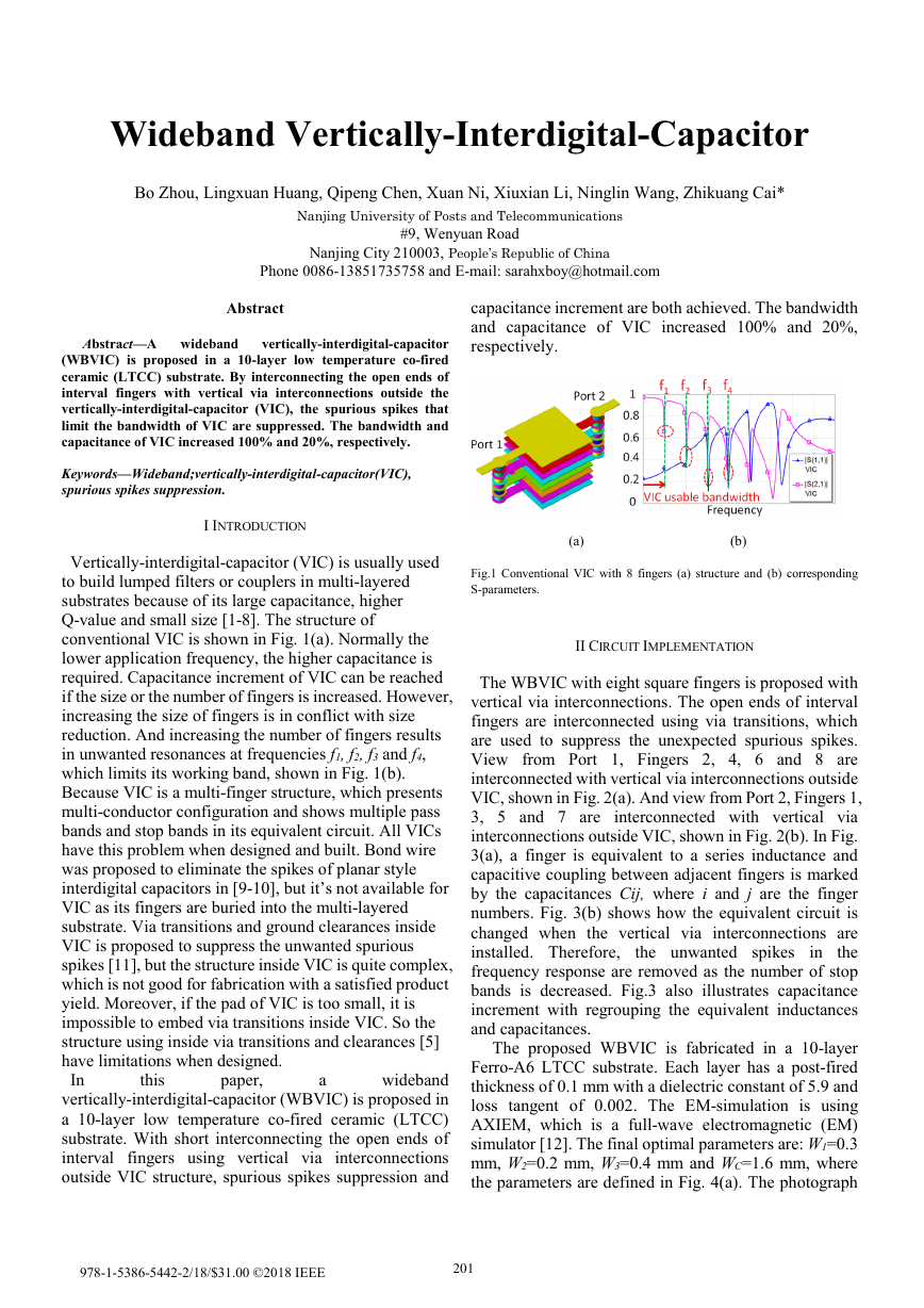
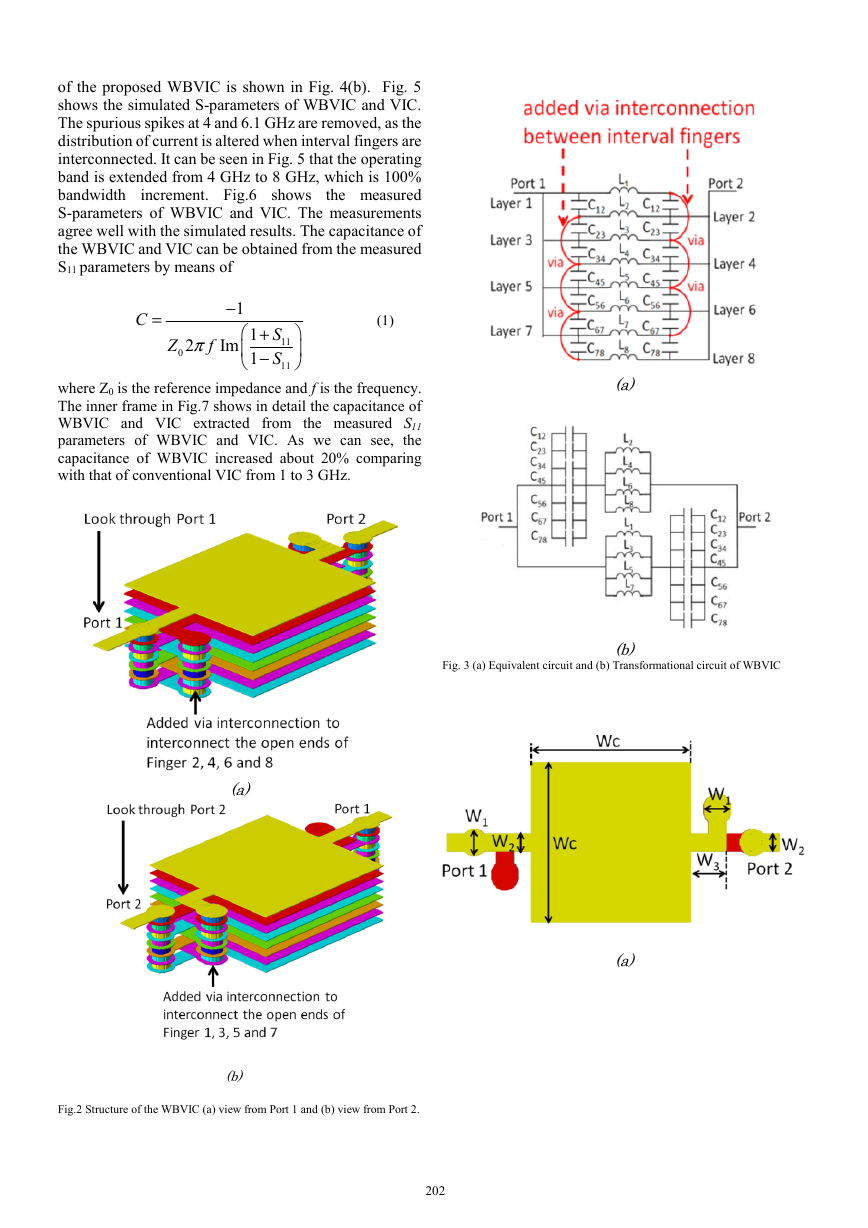
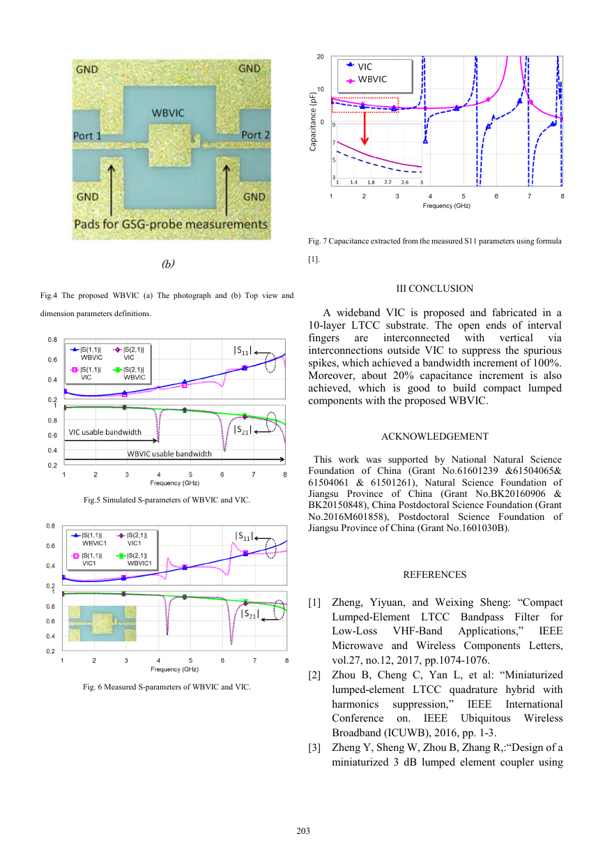
Wideband Vertically-Interdigital-Capacitor Bo Zhou, Lingxuan Huang, Qipeng Chen, Xuan Ni, Xiuxian Li, Ninglin Wang, Zhikuang Cai* Nanjing University of Posts and Telecommunications #9, Wenyuan Road Nanjing City 210003, People’s Republic of China Phone 0086-13851735758 and E-mail: sarahxboy@hotmail.com Abstract Abstract—A wideband vertically-interdigital-capacitor (WBVIC) is proposed in a 10-layer low temperature co-fired ceramic (LTCC) substrate. By interconnecting the open ends of interval fingers with vertical via interconnections outside the vertically-interdigital-capacitor (VIC), the spurious spikes that limit the bandwidth of VIC are suppressed. The bandwidth and capacitance of VIC increased 100% and 20%, respectively. Keywords—Wideband;vertically-interdigital-capacitor(VIC), spurious spikes suppression. I INTRODUCTION Vertically-interdigital-capacitor (VIC) is usually used to build lumped filters or couplers in multi-layered substrates because of its large capacitance, higher Q-value and small size [1-8]. The structure of conventional VIC is shown in Fig. 1(a). Normally the lower application frequency, the higher capacitance is required. Capacitance increment of VIC can be reached if the size or the number of fingers is increased. However, increasing the size of fingers is in conflict with size reduction. And increasing the number of fingers results in unwanted resonances at frequencies f1, f2, f3 and f4, which limits its working band, shown in Fig. 1(b). Because VIC is a multi-finger structure, which presents multi-conductor configuration and shows multiple pass bands and stop bands in its equivalent circuit. All VICs have this problem when designed and built. Bond wire was proposed to eliminate the spikes of planar style interdigital capacitors in [9-10], but it’s not available for VIC as its fingers are buried into the multi-layered substrate. Via transitions and ground clearances inside VIC is proposed to suppress the unwanted spurious spikes [11], but the structure inside VIC is quite complex, which is not good for fabrication with a satisfied product yield. Moreover, if the pad of VIC is too small, it is impossible to embed via transitions inside VIC. So the structure using inside via transitions and clearances [5] have limitations when designed. In this paper, a wideband vertically-interdigital-capacitor (WBVIC) is proposed in a 10-layer low temperature co-fired ceramic (LTCC) substrate. With short interconnecting the open ends of interval fingers using vertical via interconnections outside VIC structure, spurious spikes suppression and capacitance increment are both achieved. The bandwidth and capacitance of VIC increased 100% and 20%, respectively. (a) (b) Fig.1 Conventional VIC with 8 fingers (a) structure and (b) corresponding S-parameters. II CIRCUIT IMPLEMENTATION The WBVIC with eight square fingers is proposed with vertical via interconnections. The open ends of interval fingers are interconnected using via transitions, which are used to suppress the unexpected spurious spikes. View from Port 1, Fingers 2, 4, 6 and 8 are interconnected with vertical via interconnections outside VIC, shown in Fig. 2(a). And view from Port 2, Fingers 1, 3, 5 and 7 are interconnected with vertical via interconnections outside VIC, shown in Fig. 2(b). In Fig. 3(a), a finger is equivalent to a series inductance and capacitive coupling between adjacent fingers is marked by the capacitances Cij, where i and j are the finger numbers. Fig. 3(b) shows how the equivalent circuit is changed when the vertical via interconnections are installed. Therefore, the unwanted spikes in the frequency response are removed as the number of stop bands is decreased. Fig.3 also illustrates capacitance increment with regrouping the equivalent inductances and capacitances. The proposed WBVIC is fabricated in a 10-layer Ferro-A6 LTCC substrate. Each layer has a post-fired thickness of 0.1 mm with a dielectric constant of 5.9 and loss tangent of 0.002. The EM-simulation is using AXIEM, which is a full-wave electromagnetic (EM) simulator [12]. The final optimal parameters are: W1=0.3 mm, W2=0.2 mm, W3=0.4 mm and WC=1.6 mm, where the parameters are defined in Fig. 4(a). The photograph 978-1-5386-5442-2/18/$31.00 ©2018 IEEE�
202
of the proposed WBVIC is shown in Fig. 4(b). Fig. 5 shows the simulated S-parameters of WBVIC and VIC. The spurious spikes at 4 and 6.1 GHz are removed, as the distribution of current is altered when interval fingers are interconnected. It can be seen in Fig. 5 that the operating band is extended from 4 GHz to 8 GHz, which is 100% bandwidth increment. Fig.6 shows the measured S-parameters of WBVIC and VIC. The measurements agree well with the simulated results. The capacitance of the WBVIC and VIC can be obtained from the measured S11 parameters by means of 11011112Im1CSZfSπ−=+− (1) where Z0 is the reference impedance and f is the frequency. The inner frame in Fig.7 shows in detail the capacitance of WBVIC and VIC extracted from the measured S11 parameters of WBVIC and VIC. As we can see, the capacitance of WBVIC increased about 20% comparing with that of conventional VIC from 1 to 3 GHz. (a) (b) Fig.2 Structure of the WBVIC (a) view from Port 1 and (b) view from Port 2. (a) (b) Fig. 3 (a) Equivalent circuit and (b) Transformational circuit of WBVIC (a) �
203
(b) Fig.4 The proposed WBVIC (a) The photograph and (b) Top view and dimension parameters definitions. Fig.5 Simulated S-parameters of WBVIC and VIC. Fig. 6 Measured S-parameters of WBVIC and VIC. Fig. 7 Capacitance extracted from the measured S11 parameters using formula [1]. III CONCLUSION A wideband VIC is proposed and fabricated in a 10-layer LTCC substrate. The open ends of interval fingers are interconnected with vertical via interconnections outside VIC to suppress the spurious spikes, which achieved a bandwidth increment of 100%. Moreover, about 20% capacitance increment is also achieved, which is good to build compact lumped components with the proposed WBVIC. ACKNOWLEDGEMENT This work was supported by National Natural Science Foundation of China (Grant No.61601239 &61504065& 61504061 & 61501261), Natural Science Foundation of Jiangsu Province of China (Grant No.BK20160906 & BK20150848), China Postdoctoral Science Foundation (Grant No.2016M601858), Postdoctoral Science Foundation of Jiangsu Province of China (Grant No.1601030B). REFERENCES [1] Zheng, Yiyuan, and Weixing Sheng: “Compact Lumped-Element LTCC Bandpass Filter for Low-Loss VHF-Band Applications,” IEEE Microwave and Wireless Components Letters, vol.27, no.12, 2017, pp.1074-1076. [2] Zhou B, Cheng C, Yan L, et al: “Miniaturized lumped-element LTCC quadrature hybrid with harmonics suppression,” IEEE International Conference on. IEEE Ubiquitous Wireless Broadband (ICUWB), 2016, pp. 1-3. [3] Zheng Y, Sheng W, Zhou B, Zhang R,:“Design of a miniaturized 3 dB lumped element coupler using �
204
LTCC technology,” IEEE Asia-Pacific Microwave Conference (APMC), 2015, pp. 1-3. [4] Mousavi S H, Elzayat A, Kouki A B: “Highly compact lumped element resonators in LTCC for avionic systems,” IEEE Microwave Symposium Digest (MTT), 2012, pp.1-3. [5] Zhou, B., Wang, Q., Lu, Y., Ge, P., & Cheng, C. H. : “ 3D packaging based 4-channel LTCC receiver module,” IEEE CPMT Symposium Japan (ICSJ), 2017, pp. 71-74. [6] Zhou, B., Ma, Q., Wang, Q., Yan, L., Zhou, N., & Cheng, C. H. : “ Highly Intergrated X-Band LTCC Receiver Module,” Progress In Electromagnetics Research C, vol.71, 2017, pp. 51-58. [7] Ke Cao and Chonghu Cheng, Stacked plate capacitor design technique for filters constructed on multilayer substrates, Electron. Lett., vol.52, no.20, 2016, pp. 1695-1697. [8] Bo Zhou, Weixing Sheng and Yiyuan Zheng Miniaturized and wideband lumped LTCC branch-line coupler for dozens of megahertz aplicaitons, Microwave and optical technology letter, vol.56, no.9, 2014, pp. 2001-2005. [9] F. P. Casares-Miranda, P. Otero, E. Marquez-Segura, and C. Camacho-Penalosa, Wire bonded interdigital capacitor, IEEE Microw. Wireless Compon. Lett., vol.15, no.10, 2005, pp. 700-702. [10] Page, J. E., Marquez-Segura, E., Casares-Miranda, F. P., Esteban, J., Otero, P., & Camacho-Penalosa, C., Exact analysis of the wire-bonded multiconductor transmission line, IEEE Trans. Microw. Theory Tech., 2007, vol.55, no.8, 2007, pp.1585-1592. [11] Bo Zhou and Weixing sheng, Miniaturized lumped-Element LTCC filter with spurious spikes suppressed vertically-Interdigital-Capacitors, IEEE Microw. Wireless Compon. Lett., vol.24, no.10, 2014, pp. 692-694. [12] AXIEM, Applied Wave Research Corporation, El Segundo, CA �


 2023年江西萍乡中考道德与法治真题及答案.doc
 2012年重庆南川中考生物真题及答案.doc
 2013年江西师范大学地理学综合及文艺理论基础考研真题.doc
 2020年四川甘孜小升初语文真题及答案I卷.doc
 2020年注册岩土工程师专业基础考试真题及答案.doc
 2023-2024学年福建省厦门市九年级上学期数学月考试题及答案.doc
 2021-2022学年辽宁省沈阳市大东区九年级上学期语文期末试题及答案.doc
 2022-2023学年北京东城区初三第一学期物理期末试卷及答案.doc
 2018上半年江西教师资格初中地理学科知识与教学能力真题及答案.doc
 2012年河北国家公务员申论考试真题及答案-省级.doc
 2020-2021学年江苏省扬州市江都区邵樊片九年级上学期数学第一次质量检测试题及答案.doc
 2022下半年黑龙江教师资格证中学综合素质真题及答案.doc