logo资料库

西门子PN-CANOPEN网关技术手册.pdf

第1页 / 共126页
第2页 / 共126页
第3页 / 共126页
第4页 / 共126页
第5页 / 共126页
第6页 / 共126页
第7页 / 共126页
第8页 / 共126页
资料共126页,剩余部分请下载后查看
SIMATIC PN/CAN LINK 03/2017
Overview
Legal information
Table of contents
1 Introduction
1.1 Preface
1.2 Documentation guide
2 Safety instructions
2.1 Safety instructions
2.2 Security information
3 System overview
3.1 Field of application
3.2 System configuration
3.3 System requirements
3.4 Design
4 Functions
4.1 CANopen
4.1.1 Basic functions
4.1.1.1 Overview
4.1.1.2 Object dictionary
4.1.1.3 Process data objects (PDO)
4.1.1.4 Service Data Objects (SDO)
4.1.1.5 EMCY messages
4.1.1.6 Heartbeat / Node Guarding
4.1.1.7 SYNC messages
4.1.1.8 Data exchange between controller and PN/CAN LINK
4.1.1.9 Conversion of data formats between PROFINET and CANopen
4.1.2 CANopen Manager
4.1.2.1 State model
4.1.2.2 Control and status information
4.1.2.3 Acyclic data exchange between controller and PN/CAN LINK
4.1.2.4 Monitoring functions
4.1.3 CANopen Slave
4.1.3.1 Object dictionary
4.1.3.2 State model
4.1.3.3 Control and status information
4.1.3.4 Monitoring functions
4.1.4 Response to errors
4.2 CAN transparent
4.2.1 Overview
4.2.2 State model
4.2.3 CAN messages
4.2.4 Control and status information
4.2.5 Cyclic data exchange between controller and PN/CAN LINK for configured CAN messages
4.2.6 Cyclic data exchange between controller and PN/CAN LINK for programmed CAN messages
4.2.7 Response to errors
5 Application planning
5.1 Installation guidelines
5.2 Installation location
5.3 Transportation
5.4 Storage
5.5 Scope of delivery
6 Mounting / Extending
6.1 Installing the device
7 Connecting
7.1 Safety instructions and guidelines
7.2 Potential ratios
7.3 24 V DC power supply
7.4 Connecting the functional ground
7.5 Connecting PROFINET
7.6 Connecting the CAN bus
8 Commissioning
8.1 Commissioning the PN/CAN LINK
9 Configuring / Programming
9.1 Configuring CANopen Manager
9.1.1 Overview
9.1.2 Configuration view in the TIA Portal
9.2 Configuring CANopen Slave
9.2.1 Overview
9.2.2 Configuring in the TIA Portal
9.3 Configuring CAN transparent
9.3.1 Overview
9.3.2 Configuring in the TIA Portal
10 Diagnostics
10.1 Status LEDs
10.1.1 Operating state of the PN/CAN LINK / PROFINET diagnostics
10.1.2 Connection status CAN bus in the two CANopen operating modes
10.1.3 Connection status CAN bus in "CAN transparent" operating mode
10.2 Diagnostic messages to the S7 controller
10.2.1 Events that trigger a diagnostic message
10.2.2 Diagnostic messages
11 Maintenance and service
11.1 Firmware update
11.2 Replacing the PN/CAN LINK
11.3 Recycling and disposal
12 Technical specifications
12.1 Technical specifications of the PN/CAN LINK
12.2 Dimension drawing
A Appendix
A.1 Certificates and approvals
A.2 Contact address
A.3 Licenses
A.4 Service & Support
A.4.1 Technical Support
A.4.2 Siemens Industry Online Support
A.4.3 Online catalog and ordering system
Glossary
Index
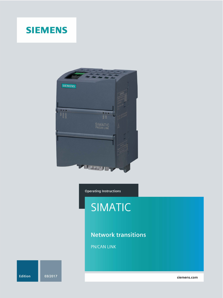
1 ___________________ Introduction 2 ___________________ Safety instructions ___________________ 3 System overview ___________________ 4 Functions ___________________ 5 Application planning ___________________ 6 Mounting / Extending ___________________ 7 Connecting ___________________ 8 Commissioning ___________________ 9 Configuring / Programming ___________________ 10 Diagnostics ___________________ 11 Maintenance and service ___________________ 12 Technical specifications ___________________ A Appendix SIMATIC Network transitions SIMATIC PN/CAN LINK Operating Instructions 03/2017 A5E39895388-AA
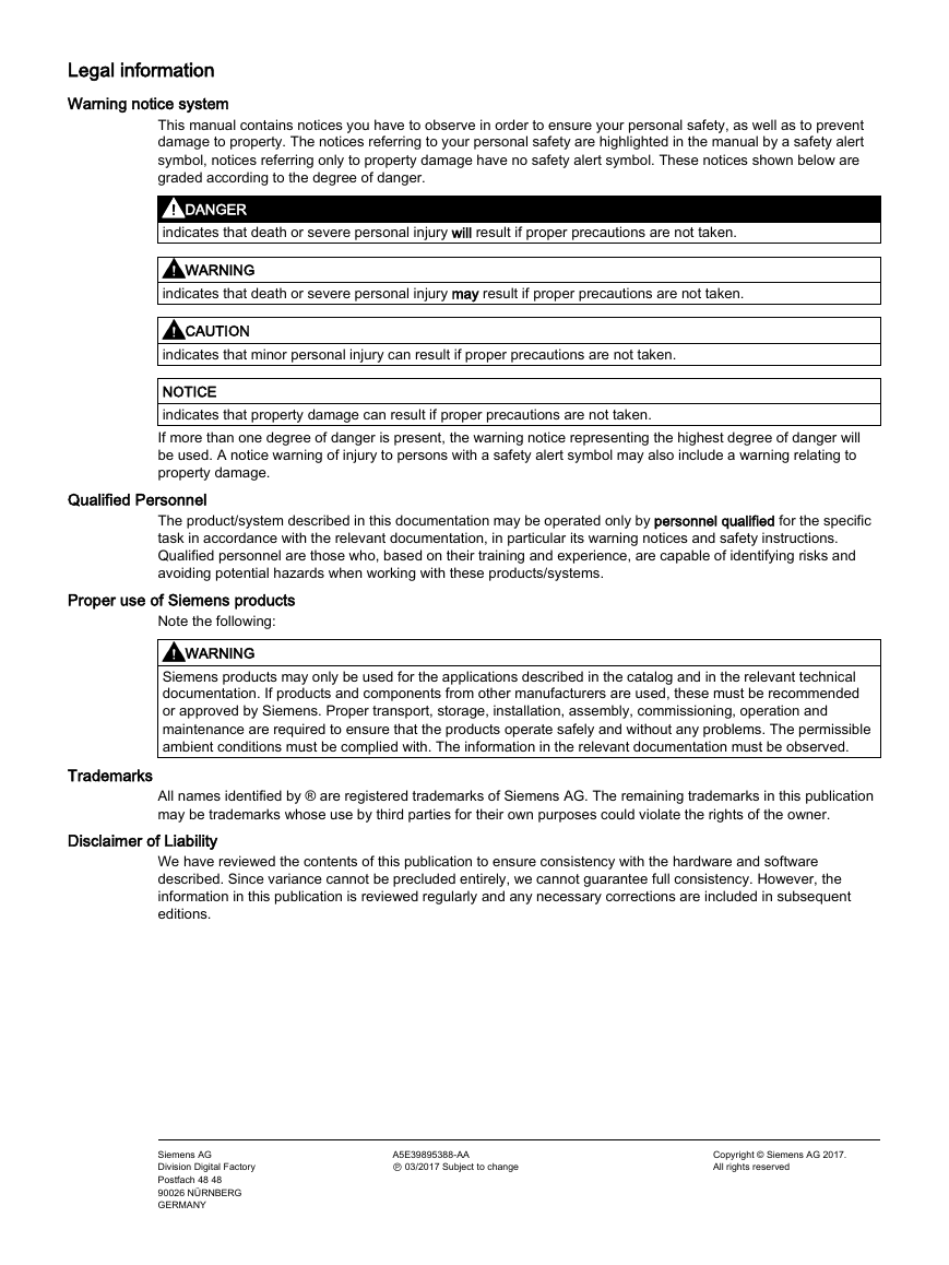
Legal information Warning notice system This manual contains notices you have to observe in order to ensure your personal safety, as well as to prevent damage to property. The notices referring to your personal safety are highlighted in the manual by a safety alert symbol, notices referring only to property damage have no safety alert symbol. These notices shown below are graded according to the degree of danger. DANGER indicates that death or severe personal injury will result if proper precautions are not taken. WARNING indicates that death or severe personal injury may result if proper precautions are not taken. CAUTION indicates that minor personal injury can result if proper precautions are not taken. NOTICE indicates that property damage can result if proper precautions are not taken. If more than one degree of danger is present, the warning notice representing the highest degree of danger will be used. A notice warning of injury to persons with a safety alert symbol may also include a warning relating to property damage. Qualified Personnel The product/system described in this documentation may be operated only by personnel qualified for the specific task in accordance with the relevant documentation, in particular its warning notices and safety instructions. Qualified personnel are those who, based on their training and experience, are capable of identifying risks and avoiding potential hazards when working with these products/systems. Proper use of Siemens products Note the following: WARNING Siemens products may only be used for the applications described in the catalog and in the relevant technical documentation. If products and components from other manufacturers are used, these must be recommended or approved by Siemens. Proper transport, storage, installation, assembly, commissioning, operation and maintenance are required to ensure that the products operate safely and without any problems. The permissible ambient conditions must be complied with. The information in the relevant documentation must be observed. Trademarks All names identified by ® are registered trademarks of Siemens AG. The remaining trademarks in this publication may be trademarks whose use by third parties for their own purposes could violate the rights of the owner. Disclaimer of Liability We have reviewed the contents of this publication to ensure consistency with the hardware and software described. Since variance cannot be precluded entirely, we cannot guarantee full consistency. However, the information in this publication is reviewed regularly and any necessary corrections are included in subsequent editions. Siemens AG Division Digital Factory Postfach 48 48 90026 NÜRNBERG GERMANY A5E39895388-AA Ⓟ 03/2017 Subject to change Copyright © Siemens AG 2017. All rights reserved
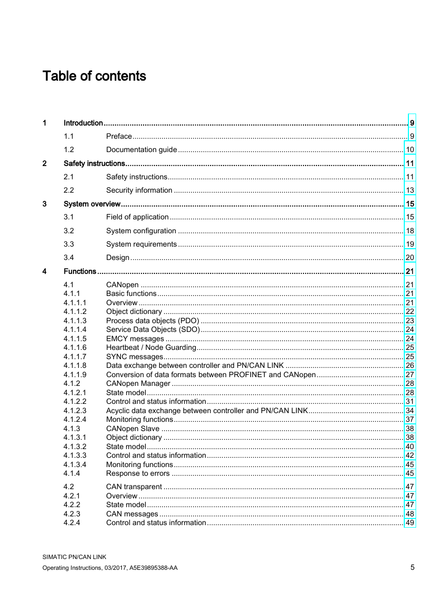
Table of contents 1 2 3 4 Introduction ............................................................................................................................................. 9 1.1 Preface ...................................................................................................................................... 9 1.2 Documentation guide .............................................................................................................. 10 Safety instructions ................................................................................................................................. 11 2.1 Safety instructions ................................................................................................................... 11 2.2 Security information ................................................................................................................ 13 System overview ................................................................................................................................... 15 Field of application .................................................................................................................. 15 3.1 System configuration .............................................................................................................. 18 3.2 3.3 System requirements .............................................................................................................. 19 3.4 Design ..................................................................................................................................... 20 Functions .............................................................................................................................................. 21 4.1 CANopen ................................................................................................................................ 21 Basic functions ........................................................................................................................ 21 4.1.1 Overview ................................................................................................................................. 21 4.1.1.1 Object dictionary ..................................................................................................................... 22 4.1.1.2 4.1.1.3 Process data objects (PDO) ................................................................................................... 23 Service Data Objects (SDO) ................................................................................................... 24 4.1.1.4 EMCY messages .................................................................................................................... 24 4.1.1.5 Heartbeat / Node Guarding ..................................................................................................... 25 4.1.1.6 4.1.1.7 SYNC messages ..................................................................................................................... 25 Data exchange between controller and PN/CAN LINK .......................................................... 26 4.1.1.8 Conversion of data formats between PROFINET and CANopen ........................................... 27 4.1.1.9 CANopen Manager ................................................................................................................. 28 4.1.2 State model ............................................................................................................................. 28 4.1.2.1 4.1.2.2 Control and status information ................................................................................................ 31 Acyclic data exchange between controller and PN/CAN LINK ............................................... 34 4.1.2.3 Monitoring functions ................................................................................................................ 37 4.1.2.4 CANopen Slave ...................................................................................................................... 38 4.1.3 4.1.3.1 Object dictionary ..................................................................................................................... 38 State model ............................................................................................................................. 40 4.1.3.2 Control and status information ................................................................................................ 42 4.1.3.3 Monitoring functions ................................................................................................................ 45 4.1.3.4 4.1.4 Response to errors ................................................................................................................. 45 CAN transparent ..................................................................................................................... 47 4.2 Overview ................................................................................................................................. 47 4.2.1 State model ............................................................................................................................. 47 4.2.2 4.2.3 CAN messages ....................................................................................................................... 48 Control and status information ................................................................................................ 49 4.2.4 SIMATIC PN/CAN LINK Operating Instructions, 03/2017, A5E39895388-AA 5
Table of contents 4.2.6 4.2.5 Cyclic data exchange between controller and PN/CAN LINK for configured CAN messages ............................................................................................................................... 51 Cyclic data exchange between controller and PN/CAN LINK for programmed CAN messages ............................................................................................................................... 52 4.2.7 Response to errors ................................................................................................................ 59 Application planning .............................................................................................................................. 61 5.1 Installation guidelines ............................................................................................................. 61 Installation location ................................................................................................................ 62 5.2 Transportation ........................................................................................................................ 65 5.3 5.4 Storage ................................................................................................................................... 65 5.5 Scope of delivery.................................................................................................................... 65 Mounting / Extending ............................................................................................................................ 67 6.1 Installing the device ............................................................................................................... 67 Connecting ........................................................................................................................................... 69 7.1 Safety instructions and guidelines ......................................................................................... 69 Potential ratios ....................................................................................................................... 71 7.2 24 V DC power supply ........................................................................................................... 72 7.3 7.4 Connecting the functional ground .......................................................................................... 73 Connecting PROFINET .......................................................................................................... 74 7.5 7.6 Connecting the CAN bus ....................................................................................................... 76 Commissioning ..................................................................................................................................... 77 8.1 Commissioning the PN/CAN LINK ......................................................................................... 77 Configuring / Programming ................................................................................................................... 79 9.1 Configuring CANopen Manager ............................................................................................. 80 Overview ................................................................................................................................ 80 9.1.1 Configuration view in the TIA Portal....................................................................................... 81 9.1.2 9.2 Configuring CANopen Slave .................................................................................................. 88 Overview ................................................................................................................................ 88 9.2.1 Configuring in the TIA Portal .................................................................................................. 89 9.2.2 Configuring CAN transparent ................................................................................................. 93 9.3 9.3.1 Overview ................................................................................................................................ 93 9.3.2 Configuring in the TIA Portal .................................................................................................. 94 Diagnostics ........................................................................................................................................... 99 10.1 Status LEDs ........................................................................................................................... 99 Operating state of the PN/CAN LINK / PROFINET diagnostics ............................................ 99 10.1.1 Connection status CAN bus in the two CANopen operating modes .................................... 101 10.1.2 Connection status CAN bus in "CAN transparent" operating mode .................................... 102 10.1.3 10.2 Diagnostic messages to the S7 controller ........................................................................... 103 Events that trigger a diagnostic message ............................................................................ 103 10.2.1 10.2.2 Diagnostic messages ........................................................................................................... 106 SIMATIC PN/CAN LINK Operating Instructions, 03/2017, A5E39895388-AA 5 6 7 8 9 10 6
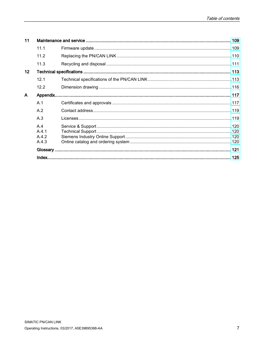
Table of contents 12 11 Maintenance and service .................................................................................................................... 109 Firmware update ................................................................................................................... 109 11.1 Replacing the PN/CAN LINK ................................................................................................ 110 11.2 11.3 Recycling and disposal ......................................................................................................... 111 Technical specifications ...................................................................................................................... 113 12.1 Technical specifications of the PN/CAN LINK ...................................................................... 113 12.2 Dimension drawing ............................................................................................................... 116 Appendix............................................................................................................................................. 117 Certificates and approvals .................................................................................................... 117 A.1 Contact address .................................................................................................................... 119 A.2 A.3 Licenses ................................................................................................................................ 119 Service & Support ................................................................................................................. 120 A.4 Technical Support ................................................................................................................. 120 A.4.1 Siemens Industry Online Support ......................................................................................... 120 A.4.2 A.4.3 Online catalog and ordering system ..................................................................................... 120 Glossary ............................................................................................................................................. 121 Index................................................................................................................................................... 125 A SIMATIC PN/CAN LINK Operating Instructions, 03/2017, A5E39895388-AA 7
Table of contents 8 SIMATIC PN/CAN LINK Operating Instructions, 03/2017, A5E39895388-AA
分享到:
收藏