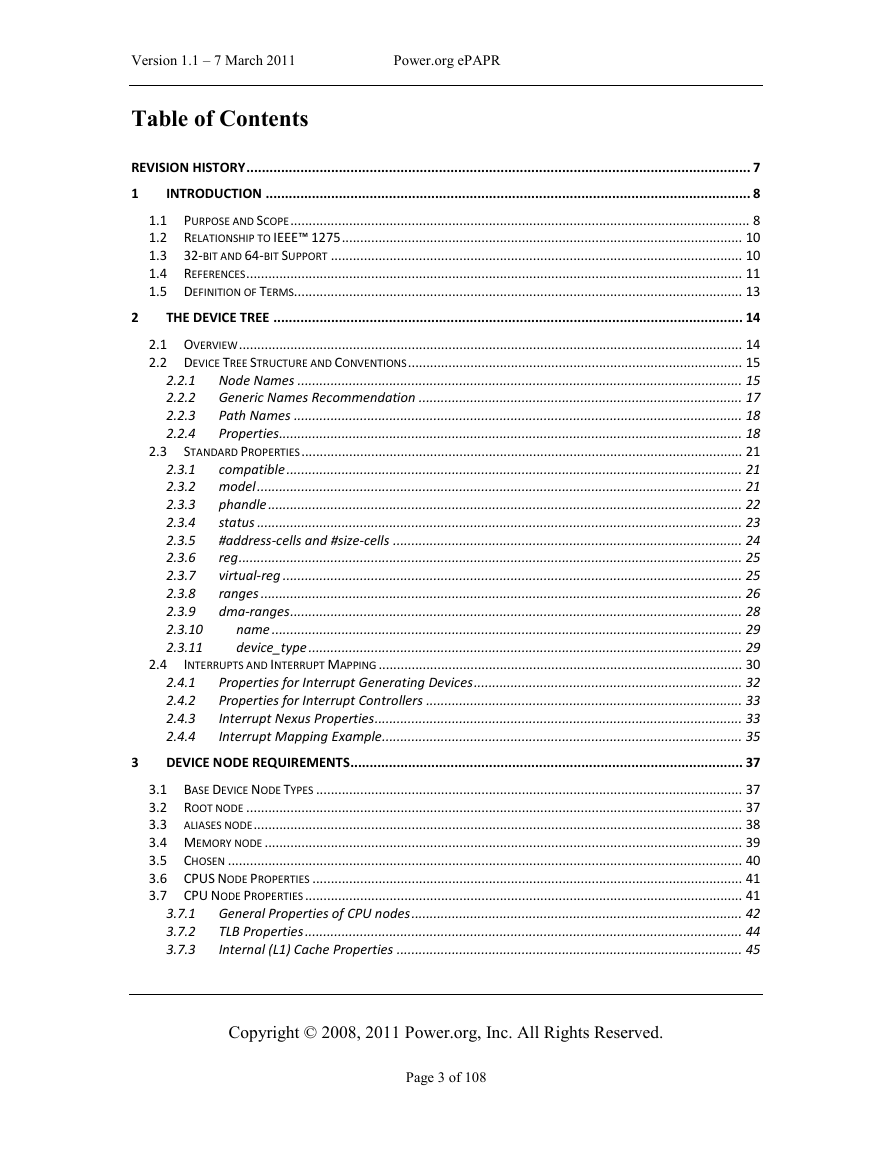
Revision History
1 Introduction
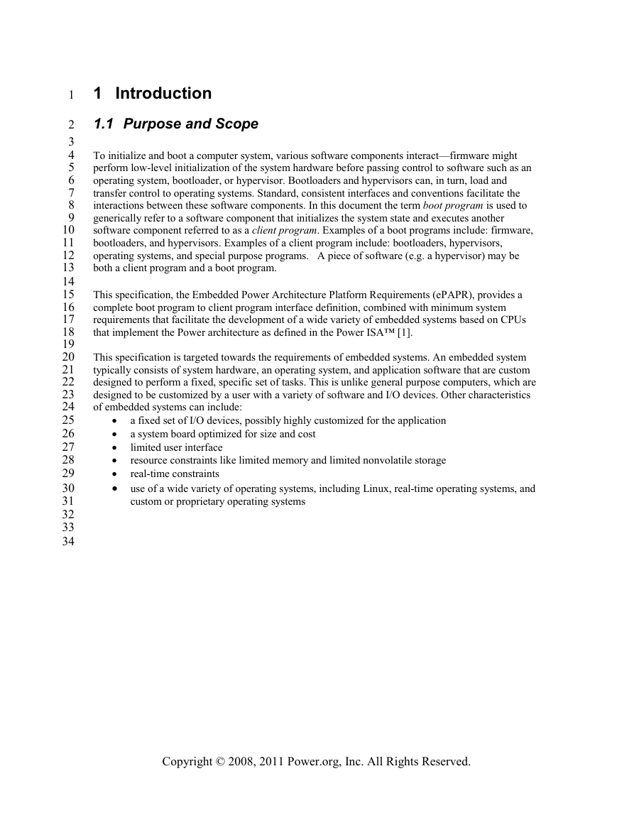
1.1 Purpose and Scope
1.2 Relationship to IEEE™ 1275
1.3 32-bit and 64-bit Support
1.4 References
1.5 Definition of Terms
2 The Device Tree
2.1 Overview
2.2 Device Tree Structure and Conventions
2.2.1 Node Names
2.2.1.1 Node Name Requirements
2.2.2 Generic Names Recommendation
2.2.3 Path Names
2.2.4 Properties
2.2.4.1 Property Names
2.2.4.2 Property Values
2.3 Standard Properties
2.3.1 compatible
2.3.2 model
2.3.3 phandle
2.3.4 status
2.3.5 #address-cells and #size-cells
2.3.6 reg
2.3.7 virtual-reg
2.3.8 ranges
2.3.9 dma-ranges
2.3.10 name
2.3.11 device_type
2.4 Interrupts and Interrupt Mapping
2.4.1 Properties for Interrupt Generating Devices
2.4.1.1 interrupts
2.4.1.2 interrupt-parent
2.4.2 Properties for Interrupt Controllers
2.4.2.1 #interrupt-cells
2.4.2.2 interrupt-controller
2.4.3 Interrupt Nexus Properties
2.4.3.1 interrupt-map
2.4.3.2 interrupt-map-mask
2.4.3.3 #interrupts-cells
2.4.4 Interrupt Mapping Example
3 Device Node Requirements
3.1 Base Device Node Types
3.2 Root node
3.3 aliases node
3.4 Memory node
3.5 Chosen
3.6 CPUS Node Properties
3.7 CPU Node Properties
3.7.1 General Properties of CPU nodes
3.7.2 TLB Properties
3.7.3 Internal (L1) Cache Properties
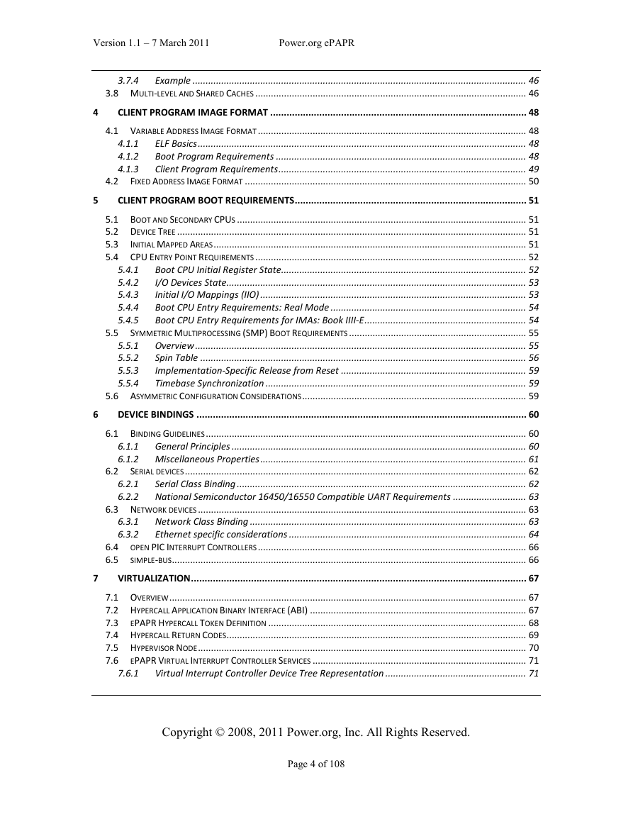
3.7.4 Example
3.8 Multi-level and Shared Caches
4 Client Program Image Format
4.1 Variable Address Image Format
4.1.1 ELF Basics
4.1.2 Boot Program Requirements
4.1.2.1 Processing of PT_LOAD segments
4.1.2.2 Entry point
4.1.3 Client Program Requirements
4.2 Fixed Address Image Format
5 Client Program Boot Requirements
5.1 Boot and Secondary CPUs
5.2 Device Tree
5.3 Initial Mapped Areas
5.4 CPU Entry Point Requirements
5.4.1 Boot CPU Initial Register State
1.1.1
5.4.2 I/O Devices State
5.4.3 Initial I/O Mappings (IIO)
5.4.4 Boot CPU Entry Requirements: Real Mode
5.4.5 Boot CPU Entry Requirements for IMAs: Book IIII-E
5.5 Symmetric Multiprocessing (SMP) Boot Requirements
5.5.1 Overview
5.5.2 Spin Table
5.5.2.1 Overview
5.5.2.2 Boot Program Requirements
5.5.2.3 Client Program Requirements
5.5.3 Implementation-Specific Release from Reset
5.5.4 Timebase Synchronization
5.6 Asymmetric Configuration Considerations
6 Device Bindings
6.1 Binding Guidelines
6.1.1 General Principles
6.1.2 Miscellaneous Properties
6.1.2.1 clock-frequency
6.1.2.2 reg-shift
6.1.2.3 label
1.1
6.2 Serial devices
6.2.1 Serial Class Binding
6.2.1.1 clock-frequency
6.2.1.2 current-speed
6.2.2 National Semiconductor 16450/16550 Compatible UART Requirements
6.3 Network devices
6.3.1 Network Class Binding
6.3.1.1 address-bits
6.3.1.2 local-mac-address
6.3.1.3 mac-address
6.3.1.4 max-frame-size
6.3.2 Ethernet specific considerations
6.3.2.1 max-speed
6.3.2.2 phy-connection-type
6.3.2.3 phy-handle
6.4 open PIC Interrupt Controllers
6.5 simple-bus
7 Virtualization
7.1 Overview
7.2 Hypercall Application Binary Interface (ABI)
7.3 ePAPR Hypercall Token Definition
7.4 Hypercall Return Codes
7.5 Hypervisor Node
7.6 ePAPR Virtual Interrupt Controller Services
1.1.1
7.6.1 Virtual Interrupt Controller Device Tree Representation
7.6.1.1 Interrupt Controller Node
7.6.1.2 Interrupt Specifiers
7.6.1.3 IPI Representation
7.6.2 ePAPR Interrupt Controller Hypercalls
7.6.2.1 EV_INT_SET_CONFIG
7.6.2.2 EV_INT_GET_CONFIG
7.6.2.3 EV_INT_SET_MASK
7.6.2.4 EV_INT_GET_MASK
7.6.2.5 EV_INT_IACK
7.6.2.6 EV_INT_EOI
7.6.2.7 EV_INT_SEND_IPI
7.6.2.8 EV_INT_SET_TASK_PRIORITY
7.6.2.9 EV_INT_GET_TASK_PRIORITY
7.7 Byte-channel Services
7.7.1 Overview
7.7.2 Interrupts and Guest Device Tree Representation
7.7.3 Byte-channel Hypercalls
7.7.3.1 EV_BYTE_CHANNEL_SEND
7.7.3.2 EV_BYTE_CHANNEL_RECEIVE
7.7.3.3 EV_BYTE_CHANNEL_POLL
7.8 Inter-partition Doorbells
7.8.1 Overview
7.8.2 Doorbell Send Endpoints
7.8.3 Doorbell Receive Endpoints
7.8.4 Doorbell Hypercall
7.9 msgsnd
7.9.1 EV_MSGSND
1.1
7.10 Idle
EV_IDLE
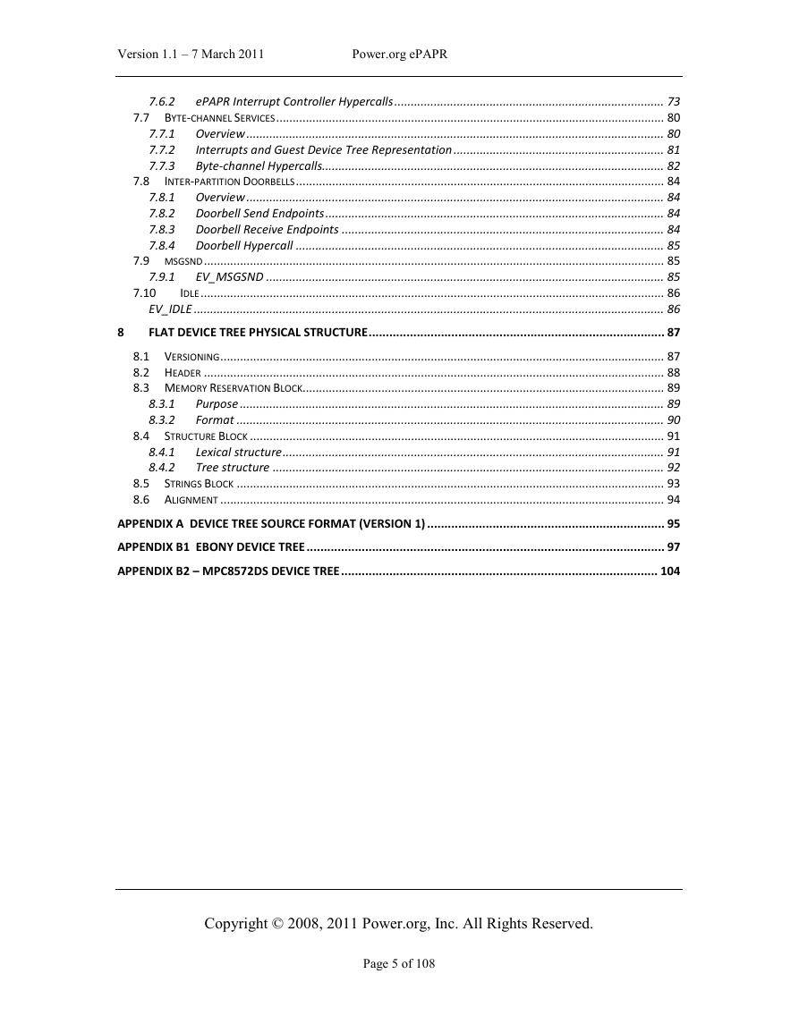
8 Flat Device Tree Physical Structure
8.1 Versioning
8.2 Header
8.3 Memory Reservation Block
8.3.1 Purpose
8.3.2 Format
8.4 Structure Block
8.4.1 Lexical structure
8.4.2 Tree structure
8.5 Strings Block
8.6 Alignment
Appendix A Device Tree Source Format (version 1)
Appendix B1 Ebony Device Tree
Appendix B2 – MPC8572DS Device Tree


 2023年江西萍乡中考道德与法治真题及答案.doc
 2012年重庆南川中考生物真题及答案.doc
 2013年江西师范大学地理学综合及文艺理论基础考研真题.doc
 2020年四川甘孜小升初语文真题及答案I卷.doc
 2020年注册岩土工程师专业基础考试真题及答案.doc
 2023-2024学年福建省厦门市九年级上学期数学月考试题及答案.doc
 2021-2022学年辽宁省沈阳市大东区九年级上学期语文期末试题及答案.doc
 2022-2023学年北京东城区初三第一学期物理期末试卷及答案.doc
 2018上半年江西教师资格初中地理学科知识与教学能力真题及答案.doc
 2012年河北国家公务员申论考试真题及答案-省级.doc
 2020-2021学年江苏省扬州市江都区邵樊片九年级上学期数学第一次质量检测试题及答案.doc
 2022下半年黑龙江教师资格证中学综合素质真题及答案.doc