logo资料库

ATJ2259C Datasheet_V1.0_100413.pdf

第1页 / 共162页
第2页 / 共162页
第3页 / 共162页
第4页 / 共162页
第5页 / 共162页
第6页 / 共162页
第7页 / 共162页
第8页 / 共162页
资料共162页,剩余部分请下载后查看
Declaration
Contents
Revision History
1 Introduction
1.1 Overview
1.2 Feature
2 Functional Block
3 PMU/DC-DC Converter
3.1 Description
3.2 Registers List
3.3 Registers Description
3.3.1 PMU_CTL
3.3.2 PMU_LRADC
3.3.3 PMU_CHG
4 CMU/HOSC, RTC/LOSC/Watch Dog, Time Count
4.1 CMU/HOSC
4.1.1 Registers List
4.1.2 Registers Description
4.1.2.1 CMU_UARTxCLK
4.1.2.2 CMU_FMCLK
4.1.2.3 CMU_DEVCLKEN
4.1.2.4 CMU_DEVRST
4.2 RTC/LOSC/Watch Dog, Timer 0, 1
4.2.1 Description
4.2.1.1 2HZ
4.2.1.2 Calendar
4.2.1.3 Alarm
4.2.1.4 Watch Dog
4.2.1.5 TIMER0/1
4.2.2 Registers List
4.2.3 Registers Description
4.2.3.1 RTC_CTL
4.2.3.2 RTC_DHMS
4.2.3.3 RTC_YMD
4.2.3.4 RTC_DHMSALM
4.2.3.5 RTC_YMDALM
4.2.3.6 RTC_WDCTL
4.2.3.7 RTC_T0CTL
4.2.3.8 RTC_T0
4.2.3.9 RTC_T1CTL
4.2.3.10 RTC_T1
5 Interrupt Controller
5.1 Description
5.1.1 Interrupt Sources
5.1.2 External Interrupt Sources
5.2 Registers Lists
5.3 Registers Description
5.3.1 INTC_PD
5.3.2 INTC_MSK
5.3.3 INTC_CFGx
5.3.4 INTC_EXTCTL
6 32bit Mips24KEc Core
7 DMA
8 SDRAM Interface
8.1 Description
9 SPI Interface
9.1 Registers List
9.2 Registers Description
9.2.1 SPI_CTL
9.2.2 SPI_CLKDIV
9.2.3 SPI_STAT
9.2.4 SPI_RXDAT
9.2.5 SPI_TXDAT
10 Nand Flash/SMC Interface
11 SD/MMC/SDIO Controller
12 Memory Stick (MS)
13 YUV2RGB/LDC
13.1 Description
13.2 Registers List
13.3 Registers Description
13.3.1 YUV2RGB_CTL
13.3.2 YUV2RGB_DAT
13.3.3 YUV2RGB_CLKCTL
13.3.4 YUV2RGB_FrameCount
13.4 YUV2RGB Hardware Description
14 LDR Controller
14.1 Description
14.2 Feature
14.3 Registers List
14.4 Registers Description
14.4.1 LCD_Ctrl0
14.4.2 LCD_Size
14.4.3 LCD_Status
14.4.4 LCD_RGBTiming0
14.4.5 LCD_RGBTiming1
14.4.6 LCD_RGBTiming2
14.4.7 LCD_Color
14.4.8 LCD_PWM
14.4.9 LCD_FIFODAT
14.5 Pin Assignment
15 DAC, I2S Port and Headphone Driver
16 ADC
17 SPDIF Interface
17.1 Registers List
17.2 Registers Description
17.2.1 SPDIF_CTL
17.2.2 SPDIF_STAT
17.2.3 SPDIF_ TXDAT
17.2.4 SPDIF_ RXDAT
17.2.5 SPDIF_ TXCSTAT
17.2.6 SPDIF_ RXCSTAT
17.3 SPDIF Signals Description
18 UART (2) Interface
18.1 Description
18.2 Registers List
18.3 Registers Description
18.3.1 UART1_CTL
18.3.2 UART1_RXDAT
18.3.3 UART1_TXDAT
18.3.4 UART1_STAT
18.3.5 UART2_CTL
18.3.6 UART2_RXDAT
18.3.7 UART2_TXDAT
18.3.8 UART2_STAT
18.4 UART Signals Description
19 IR Interface
19.1 Description
19.2 Registers List
19.3 Registers Description
19.3.1 IR_PL
19.3.2 IR_RBC
20 I2C (2) Interface
20.1 Description
20.2 Registers List
20.3 Registers Decription
20.3.1 I2Cx_CTL
20.3.2 I2Cx_CLKDIV
20.3.3 I2Cx_STAT
20.3.4 I2Cx_ADDR
20.3.5 I2Cx_DAT
20.4 I2C Signals Description
21 Key Scan
21.1 Description
21.2 Registers List
21.3 Key Scan Registers Description
21.3.1 KEY_CTL
21.3.2 KEY_DAT0
21.3.3 KEY_DAT1
21.3.4 KEY_DAT2
21.3.5 KEY_DAT3
22 GPIO_MFP
22.1 Description
22.1.1 Uart/IR/I2C/SPI/SPDIF
22.1.2 GPIO/Function Pin
22.1.3 RGB/Function Pin
22.1.4 Pad with Build-in Resistance
22.2 Registers List
22.3 Registers Description
22.3.1 GPIO_AOUTEN
22.3.2 GPIO_AINEN
22.3.3 GPIO_ADAT
22.3.4 GPIO_BOUTEN
22.3.5 GPIO_BINEN
22.3.6 GPIO_BDAT
22.3.7 GPIO_MFCTL1
22.3.8 GPIO_MFCTL2
22.3.9 PAD_DRV
23 Electrical Characteristics
23.1 Absolute Maximum Ratings
23.2 DC Characteristics
23.3 AC Characteristics
23.3.1 AC Test Input Waveform
23.3.2 AC Test Output Measuring Points
23.4 Reset Parameter
23.5 Initialization Parameter
23.6 PMU
23.6.1 DC/DC Operates Voltage
23.6.2 System Standby Dissipation
23.6.3 LRADC
23.7 GPIO Interface Parameter
23.8 Ordinary ROM Parameter
23.9 External System Bus Parameter
23.10 Bus Operation
23.11 SPI Parameter
23.12 SPDIF Interface Parameter
23.13 I2C Interface Parameter
23.14 A/D Converter Characteristics
23.15 D/A Converter Characteristics
23.16 Headphone Driver Characteristics
23.17 LCM Driver Parameter
23.17.1 LDC LCM Driver Parameter
23.17.2 LDR LCM Driver Parameter
23.18 CMOS Sensor Timing (same with BT601)
23.19 Encoder IF
23.20 Decoder IF (BT656, BT601)
23.21 NAND Flash IF
23.22 SD/MMC IF
23.23 MS IF
23.24 SDRAM IF
24 Pin Definition
24.1 Pin Sort by Pin Number
24.2 ATJ2259C Pin Definition
25 ATJ2259C Package Drawing
26 Appendix
26.1 Acronym and Abbreviations
ATJ2259C Datasheet Latest Version: 1.0 2010-04-13
ATJ2259C DATASHEET Declaration Circuit diagrams and other information relating to products of Actions Semiconductor Company, Ltd. (“Actions”) are included as a means of illustrating typical applications. Consequently, complete information sufficient for construction is not necessarily given. Although the information has been examined and is believed to be accurate, Actions makes no representations or warranties with respect to the accuracy or completeness of the contents of this publication and disclaims any responsibility for inaccuracies. Information in this document is provided solely to enable use of Actions’ products. The information presented in this document does not form part of any quotation or contract of sale. Actions assumes no liability whatsoever, including infringement of any patent or copyright, for sale and use of Actions’ products, except as expressed in Actions’ Terms and Conditions of Sale for. All sales of any Actions products are conditional on your agreement of the terms and conditions of recently dated version of Actions’ Terms and Conditions of Sale agreement Dated before the date of your order. This information does not convey to the purchaser of the described semiconductor devices any licenses under any patent rights, copyright, trademark rights, rights in trade secrets and/or know how, or any other intellectual property rights of Actions or others, however denominated, whether by express or implied representation, by estoppel, or otherwise. Information Documented here relates solely to Actions products described herein supersedes, as of the release date of this publication, all previously published data and specifications relating to such products provided by Actions or by any other person purporting to distribute such information. Actions reserve the right to make changes to specifications and product descriptions at any time without notice. Contact your Actions sales representative to obtain the latest specifications before placing your product order. Actions product may contain design defects or errors known as anomalies or errata which may cause the products functions to deviate from published specifications. Anomaly or “errata” sheets relating to currently characterized anomalies or errata are available upon request. Designers must not rely on the absence or characteristics of any features or instructions of Actions’ products marked “Reserved” or “undefined.” Actions reserves these for future definition and shall have no responsibility whatsoever for conflicts or incompatibilities arising from future changes to them. Actions’ products are not designed, intended, authorized or warranted for use in any life support or other application where product failure could cause or contribute to personal injury or severe property damage. Any and all such uses without prior written approval of an Officer of Actions and further testing and/or modification will be fully at the risk of the Copyright © Actions Semiconductor Co., Ltd. 2010. All Rights Reserved. Version 1.0 Page 2
customer. ATJ2259C DATASHEET Copies of this document and/or other Actions product literature, as well as the Terms and Conditions of Sale Agreement, may be obtained by visiting Actions’ website at http://www.actions-semi.com/ or from an authorized Actions representative. The word “ACTIONS”, the Actions’ LOGO, whether used separately and/or in combination, and the phase “ATJ2259C” are trademarks of Actions Semiconductor Company, Ltd., Names and brands of other companies and their products that may from time to time descriptively appear in this product data sheet are the trademarks of their respective holders; no affiliation, authorization, or endorsement by such persons is claimed or implied except as may be expressly stated therein. ACTIONS DISCLAIMS AND EXCLUDES ANY AND ALL WARRANTIES, INCLUDING WITHOUT LIMITATION ANY AND ALL IMPLIED WARRANTIES OF MERCHANTABILITY, FITNESS FOR A PARTICULAR PURPOSE, TITLE, AND AGAINST INFRINGEMENT AND THE LIKE, AND ANY AND ALL WARRANTIES ARISING FROM ANY COURSE OF DEALING OR USAGE OF TRADE. IN NO EVENT SHALL ACTIONS BE RELIABLE FOR ANY DIRECT, INCIDENTAL, INDIRECT, SPECIAL, PUNITIVE, OR CONSEQUENTIAL DAMAGES; OR FOR LOST DATA, PROFITS, SAVINGS OR REVENUES OF ANY KIND; REGARDLESS OF THE FORM OF ACTION, WHETHER BASED ON CONTRACT; TORT; NEGLIGENCE OF ACTIONS OR OTHERS; STRICT LIABILITY; BREACH OF WARRANTY; OR OTHERWISE; WHETHER OR NOT ANY REMEDY OF BUYER IS HELD TO HAVE FAILED OF ITS ESSENTIAL PURPOSE, AND WHETHER ACTIONS HAS BEEN ADVISED OF THE POSSIBILITY OF SUCH DAMAGES OR NOT. Additional Support Additional product and company information can be obtained by visiting the Actions website at: http://www.actions-semi.com Copyright © Actions Semiconductor Co., Ltd. 2010. All Rights Reserved. Version 1.0 Page 3
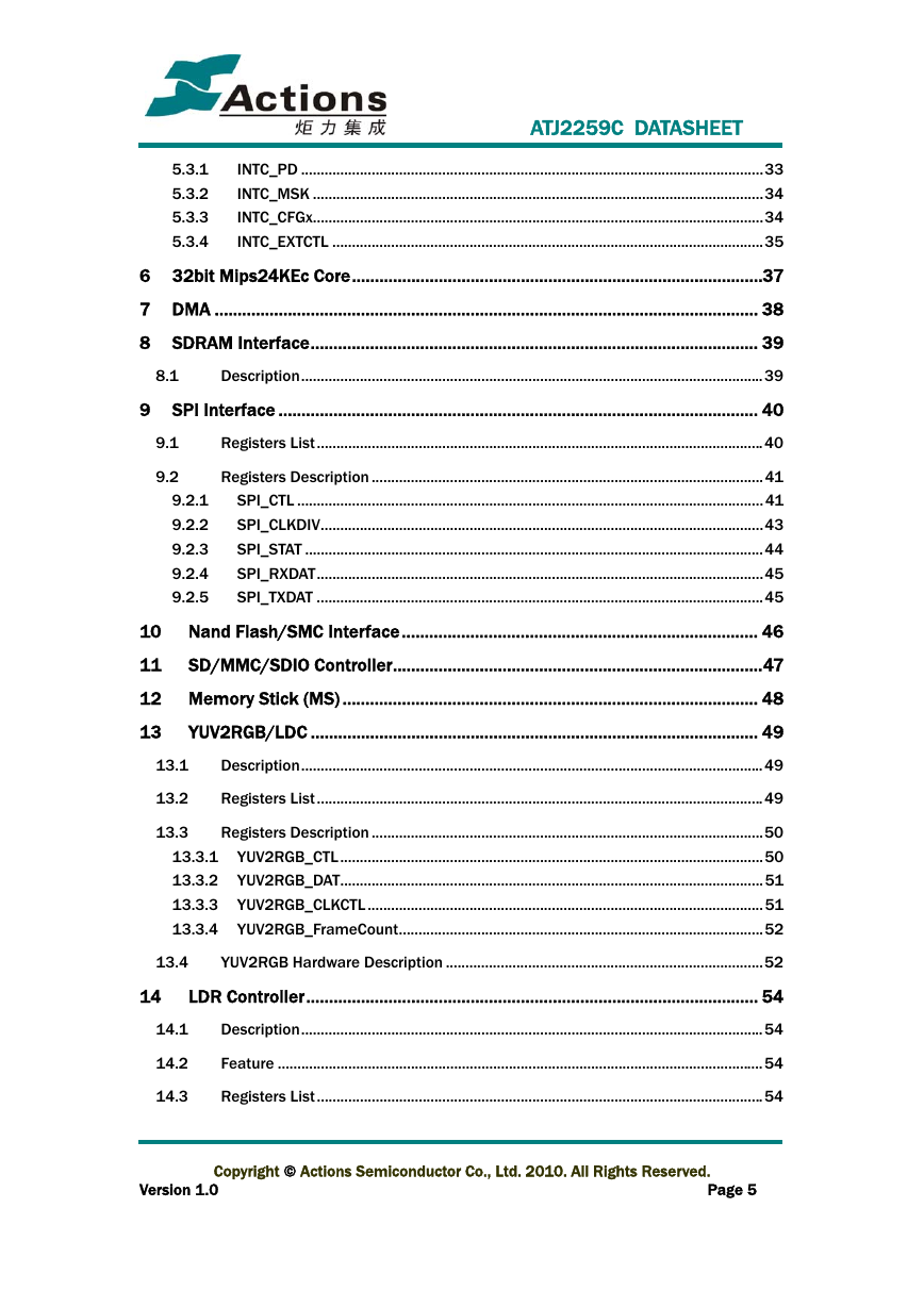
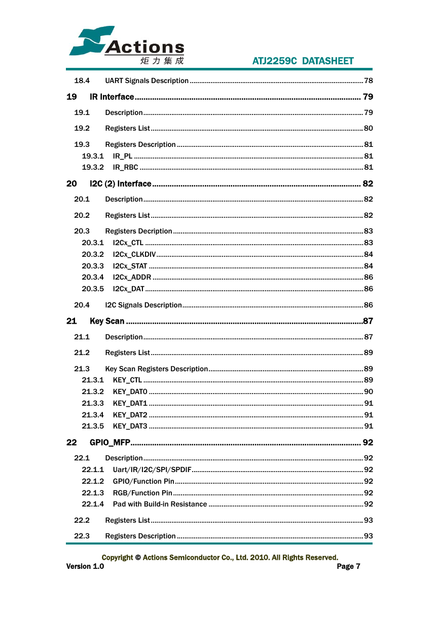
ATJ2259C DATASHEET Contents Declaration......................................................................................................................2 Contents ..........................................................................................................................4 Revision History ........................................................................................................... 10 1 Introduction........................................................................................................... 11 Overview..........................................................................................................................11 1.1 1.2 Feature ............................................................................................................................11 2 Functional Block....................................................................................................17 3 PMU/DC-DC Converter......................................................................................... 18 Description......................................................................................................................18 3.1 3.2 3.3 3.3.1 3.3.2 3.3.3 Registers List..................................................................................................................18 Registers Description ....................................................................................................18 PMU_CTL.....................................................................................................................18 PMU_LRADC ...............................................................................................................20 PMU_CHG....................................................................................................................21 4.1 4 CMU/HOSC, RTC/LOSC/Watch Dog, Time Count............................................. 23 CMU/HOSC......................................................................................................................23 Registers List..............................................................................................................23 Registers Description................................................................................................23 4.1.1 4.1.2 4.2 4.2.1 4.2.2 4.2.3 RTC/LOSC/Watch Dog, Timer 0, 1..............................................................................25 Description..................................................................................................................25 Registers List..............................................................................................................26 Registers Description................................................................................................27 5 5.1 Interrupt Controller............................................................................................... 32 Description......................................................................................................................32 Interrupt Sources .......................................................................................................32 External Interrupt Sources........................................................................................33 5.1.1 5.1.2 Registers Lists ................................................................................................................33 Registers Description ....................................................................................................33 5.2 5.3 Copyright © Actions Semiconductor Co., Ltd. 2010. All Rights Reserved. Version 1.0 Page 4
ATJ2259C DATASHEET 5.3.1 5.3.2 5.3.3 5.3.4 INTC_PD ......................................................................................................................33 INTC_MSK ...................................................................................................................34 INTC_CFGx...................................................................................................................34 INTC_EXTCTL ..............................................................................................................35 6 32bit Mips24KEc Core..........................................................................................37 7 DMA ....................................................................................................................... 38 8 SDRAM Interface.................................................................................................. 39 Description......................................................................................................................39 8.1 9 SPI Interface ......................................................................................................... 40 Registers List..................................................................................................................40 9.1 9.2 9.2.1 9.2.2 9.2.3 9.2.4 9.2.5 Registers Description ....................................................................................................41 SPI_CTL .......................................................................................................................41 SPI_CLKDIV.................................................................................................................43 SPI_STAT .....................................................................................................................44 SPI_RXDAT..................................................................................................................45 SPI_TXDAT ..................................................................................................................45 10 Nand Flash/SMC Interface.............................................................................. 46 11 SD/MMC/SDIO Controller.................................................................................47 12 Memory Stick (MS) ........................................................................................... 48 13 YUV2RGB/LDC .................................................................................................. 49 Description......................................................................................................................49 13.1 13.2 Registers List..................................................................................................................49 13.3 Registers Description ....................................................................................................50 13.3.1 YUV2RGB_CTL............................................................................................................50 13.3.2 YUV2RGB_DAT............................................................................................................51 13.3.3 YUV2RGB_CLKCTL .....................................................................................................51 13.3.4 YUV2RGB_FrameCount.............................................................................................52 13.4 YUV2RGB Hardware Description .................................................................................52 14 LDR Controller................................................................................................... 54 Description......................................................................................................................54 14.1 Feature ............................................................................................................................54 Registers List..................................................................................................................54 14.2 14.3 Copyright © Actions Semiconductor Co., Ltd. 2010. All Rights Reserved. Version 1.0 Page 5
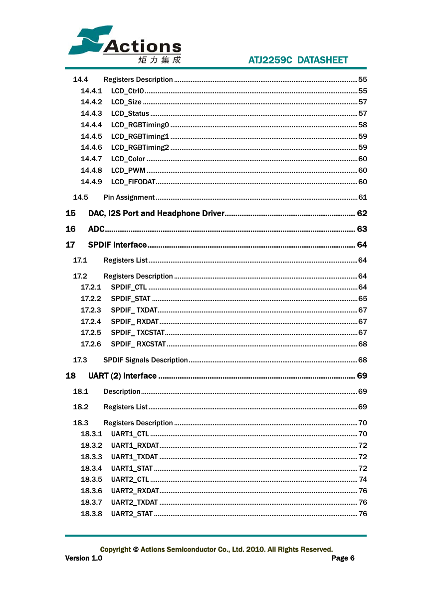
ATJ2259C DATASHEET 14.4 Registers Description ....................................................................................................55 14.4.1 LCD_Ctrl0 ....................................................................................................................55 14.4.2 LCD_Size .....................................................................................................................57 14.4.3 LCD_Status .................................................................................................................57 14.4.4 LCD_RGBTiming0 ......................................................................................................58 14.4.5 LCD_RGBTiming1 ......................................................................................................59 14.4.6 LCD_RGBTiming2 ......................................................................................................59 14.4.7 LCD_Color ...................................................................................................................60 14.4.8 LCD_PWM ...................................................................................................................60 14.4.9 LCD_FIFODAT..............................................................................................................60 14.5 Pin Assignment ..............................................................................................................61 15 DAC, I2S Port and Headphone Driver............................................................. 62 16 17 ADC..................................................................................................................... 63 SPDIF Interface................................................................................................. 64 Registers List..................................................................................................................64 17.1 17.2 Registers Description ....................................................................................................64 17.2.1 SPDIF_CTL ..................................................................................................................64 17.2.2 SPDIF_STAT ................................................................................................................65 17.2.3 SPDIF_ TXDAT.............................................................................................................67 17.2.4 SPDIF_ RXDAT............................................................................................................67 17.2.5 SPDIF_ TXCSTAT.........................................................................................................67 17.2.6 SPDIF_ RXCSTAT ........................................................................................................68 17.3 SPDIF Signals Description............................................................................................68 18 UART (2) Interface ............................................................................................ 69 Description......................................................................................................................69 18.1 18.2 Registers List..................................................................................................................69 18.3 Registers Description ....................................................................................................70 18.3.1 UART1_CTL .................................................................................................................70 18.3.2 UART1_RXDAT............................................................................................................72 18.3.3 UART1_TXDAT ............................................................................................................72 18.3.4 UART1_STAT ...............................................................................................................72 18.3.5 UART2_CTL ................................................................................................................. 74 18.3.6 UART2_RXDAT............................................................................................................ 76 18.3.7 UART2_TXDAT ............................................................................................................ 76 18.3.8 UART2_STAT ............................................................................................................... 76 Copyright © Actions Semiconductor Co., Ltd. 2010. All Rights Reserved. Page 6 Version 1.0
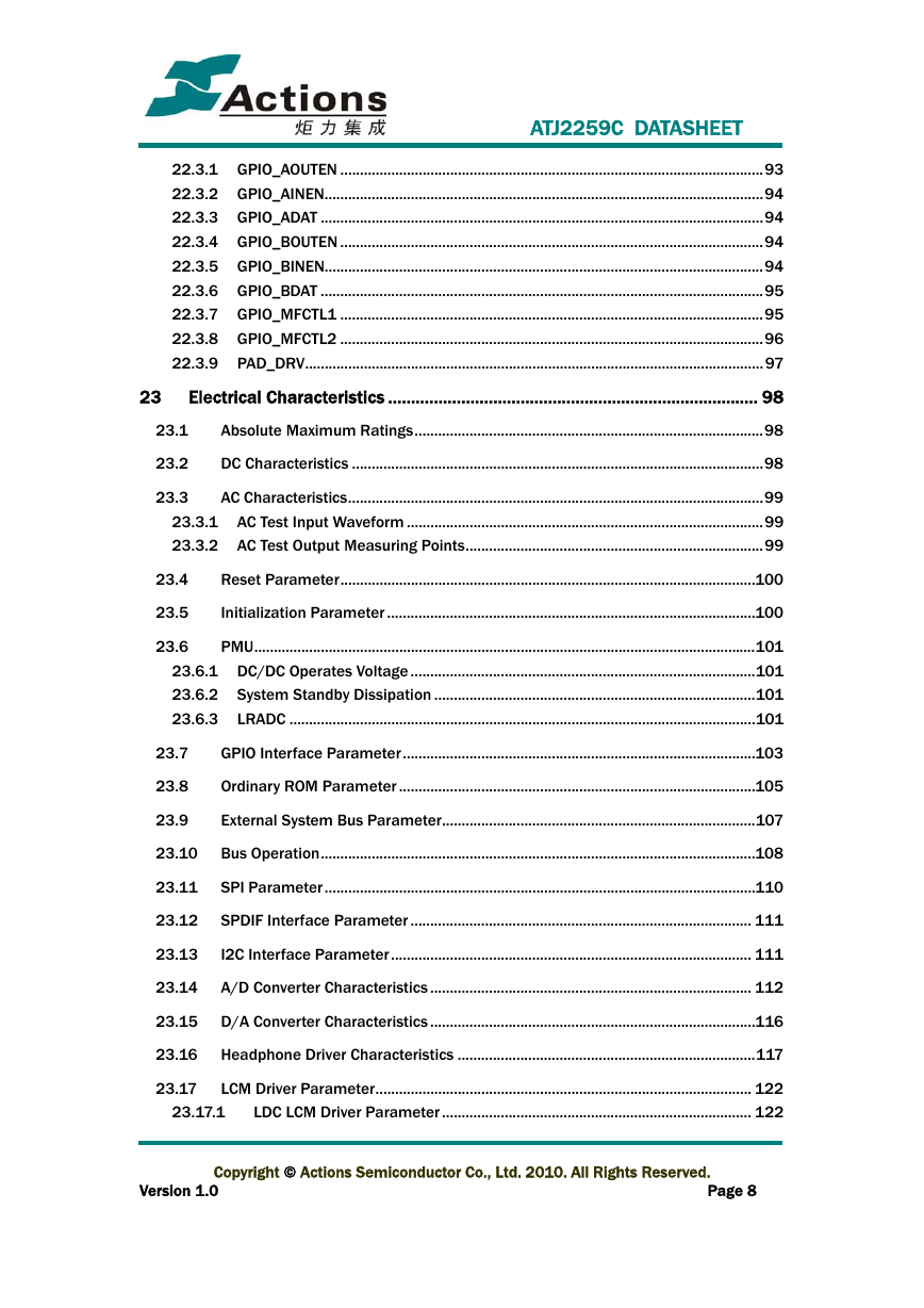
ATJ2259C DATASHEET 18.4 UART Signals Description .............................................................................................78 19 IR Interface........................................................................................................ 79 Description......................................................................................................................79 Registers List..................................................................................................................80 Registers Description ....................................................................................................81 IR_PL ........................................................................................................................... 81 IR_RBC ........................................................................................................................81 19.3.1 19.3.2 19.1 19.2 19.3 20.1 20.2 20.3 20 I2C (2) Interface................................................................................................ 82 Description......................................................................................................................82 Registers List..................................................................................................................82 Registers Decription......................................................................................................83 I2Cx_CTL .....................................................................................................................83 I2Cx_CLKDIV...............................................................................................................84 I2Cx_STAT ...................................................................................................................84 I2Cx_ADDR .................................................................................................................86 I2Cx_DAT .....................................................................................................................86 20.3.1 20.3.2 20.3.3 20.3.4 20.3.5 20.4 I2C Signals Description.................................................................................................86 21 Key Scan .............................................................................................................87 Description...................................................................................................................... 87 21.1 21.2 Registers List..................................................................................................................89 21.3 Key Scan Registers Description...................................................................................89 21.3.1 KEY_CTL ......................................................................................................................89 21.3.2 KEY_DAT0 ...................................................................................................................90 21.3.3 KEY_DAT1 ...................................................................................................................91 21.3.4 KEY_DAT2 ...................................................................................................................91 21.3.5 KEY_DAT3 ...................................................................................................................91 22.1 22 GPIO_MFP.......................................................................................................... 92 Description......................................................................................................................92 22.1.1 Uart/IR/I2C/SPI/SPDIF............................................................................................92 22.1.2 GPIO/Function Pin.....................................................................................................92 22.1.3 RGB/Function Pin......................................................................................................92 22.1.4 Pad with Build-in Resistance ...................................................................................92 22.2 22.3 Registers List..................................................................................................................93 Registers Description ....................................................................................................93 Copyright © Actions Semiconductor Co., Ltd. 2010. All Rights Reserved. Page 7 Version 1.0
23 ATJ2259C DATASHEET 22.3.1 GPIO_AOUTEN ............................................................................................................93 22.3.2 GPIO_AINEN................................................................................................................94 22.3.3 GPIO_ADAT .................................................................................................................94 22.3.4 GPIO_BOUTEN ............................................................................................................94 22.3.5 GPIO_BINEN................................................................................................................94 22.3.6 GPIO_BDAT .................................................................................................................95 22.3.7 GPIO_MFCTL1 ............................................................................................................95 22.3.8 GPIO_MFCTL2 ............................................................................................................96 22.3.9 PAD_DRV.....................................................................................................................97 Electrical Characteristics ................................................................................. 98 Absolute Maximum Ratings.........................................................................................98 23.1 23.2 DC Characteristics .........................................................................................................98 23.3 AC Characteristics..........................................................................................................99 23.3.1 AC Test Input Waveform ...........................................................................................99 23.3.2 AC Test Output Measuring Points............................................................................99 23.4 23.5 Reset Parameter..........................................................................................................100 Initialization Parameter ..............................................................................................100 23.6 PMU................................................................................................................................101 23.6.1 DC/DC Operates Voltage ........................................................................................101 23.6.2 System Standby Dissipation ..................................................................................101 23.6.3 LRADC .......................................................................................................................101 23.7 23.8 23.9 GPIO Interface Parameter..........................................................................................103 Ordinary ROM Parameter ...........................................................................................105 External System Bus Parameter................................................................................107 23.10 Bus Operation...............................................................................................................108 23.11 SPI Parameter ..............................................................................................................110 23.12 SPDIF Interface Parameter ....................................................................................... 111 23.13 I2C Interface Parameter............................................................................................ 111 23.14 A/D Converter Characteristics .................................................................................. 112 23.15 D/A Converter Characteristics ...................................................................................116 23.16 Headphone Driver Characteristics ............................................................................117 23.17 LCM Driver Parameter................................................................................................ 122 LDC LCM Driver Parameter ............................................................................... 122 23.17.1 Copyright © Actions Semiconductor Co., Ltd. 2010. All Rights Reserved. Version 1.0 Page 8
分享到:
收藏