ST7775R
176RGB x 220 dot 262K Color with Frame Memory
Single-Chip TFT Controller/Driver
Datasheet
Preliminary Version 0.1
2010/03
Sitronix Technology Corp. reserves the right to change the contents in this
document without prior notice.
�
ST7775R
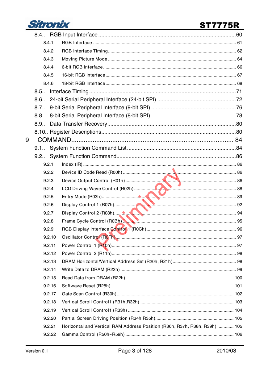
LIST OF CONTENT
1 GENERAL DESCRIPTION..................................................................... 8
2 FEATURES ............................................................................................ 9
3 PAD ARRANGEMENT ......................................................................... 11
3.1.. Pad Arrangement...............................................................................................11
3.2.. Bump Dimension ...............................................................................................12
3.3.. Alignment Mark Dimension................................................................................13
3.4.. Chip Information ................................................................................................13
4 PAD CENTER COORDINATES ........................................................... 14
5 BLOCK DIAGRAM ............................................................................... 29
6 PIN DESCRIPTION .............................................................................. 30
6.1.. Power Supply Pins.............................................................................................30
6.2..
Interface Logic Pins ...........................................................................................31
6.3.. Driver Output Pins .............................................................................................33
6.4.. Test Pins............................................................................................................34
7 DRIVER ELECTRICAL CHARACTERISTICS...................................... 35
7.1.. Absolute Operation Range ................................................................................35
7.2.. DC Characteristics.............................................................................................36
7.3.. Power Consumption ..........................................................................................37
7.4.. AC Characteristics .............................................................................................38
8080 Series MCU Parallel Interface Characteristics: 18/16/9/8-bit Bus ...................... 38
6800 Series MCU Parallel Interface Characteristics: 18/16/9/8-bit Bus ...................... 40
Serial Data Transfer Interface Characteristics: ............................................................. 41
RGB Interface Characteristics: ....................................................................................... 42
INTERFACE ......................................................................................... 44
8.1.. MCU Interface Type Selection...........................................................................44
8.2.. 8080-Series MCU Write Cycle Sequence..........................................................45
8.3.. 6800-Series MCU Write Cycle Sequence..........................................................46
18 bits Interface Write Data Format................................................................................ 47
8.3.1
16 bits Interface Write Data Format................................................................................ 48
8.3.2
9 bits Interface Write Data Format.................................................................................. 49
8.3.3
8 bits Interface Write Data Format.................................................................................. 51
8.3.4
8080-series MCU Read Cycle Sequence ........................................................................ 53
8.3.5
6800-series MCU Read Cycle Sequence ........................................................................ 54
8.3.6
18bits interface read data format.................................................................................... 55
8.3.7
16bits Interface Read Data Format ................................................................................. 56
8.3.8
9bits Interface Read Data Format ................................................................................... 57
8.3.9
8.3.10 8bits Interface Read Data Format ................................................................................... 58
7.4.1
7.4.2
7.4.3
7.4.4
8
Version 0.1 Page 2 of 128 2010/03
�
ST7775R
8.4.. RGB Input Interface ...........................................................................................60
RGB Interface ................................................................................................................... 61
8.4.1
8.4.2
RGB Interface Timing....................................................................................................... 62
8.4.3 Moving Picture Mode ....................................................................................................... 64
6-bit RGB Interface........................................................................................................... 66
8.4.4
16-bit RGB Interface......................................................................................................... 67
8.4.5
8.4.6
18-bit RGB Interface......................................................................................................... 68
8.5..
Interface Timing .................................................................................................71
8.6.. 24-bit Serial Peripheral Interface (24-bit SPI) ....................................................72
8.7.. 9-bit Serial Peripheral Interface (9-bit SPI) ........................................................76
8.8.. 8-bit Serial Peripheral Interface (8-bit SPI) ........................................................78
8.9.. Data Transfer Recovery.....................................................................................80
8.10.. Register Descriptions.........................................................................................80
9 COMMAND........................................................................................... 84
9.1.. System Function Command List........................................................................84
9.2.. System Function Command...............................................................................86
Index (IR) ........................................................................................................................... 86
9.2.1
Device ID Code Read (R00h) ........................................................................................... 86
9.2.2
Device Output Control (R01h) ......................................................................................... 86
9.2.3
LCD Driving Wave Control (R02h) .................................................................................. 88
9.2.4
Entry Mode (R03h)............................................................................................................ 89
9.2.5
Display Control 1 (R07h).................................................................................................. 92
9.2.6
Display Control 2 (R08h).................................................................................................. 94
9.2.7
Frame Cycle Control (R0Bh) ........................................................................................... 95
9.2.8
9.2.9
RGB Display Interface Control 1 (R0Ch)........................................................................ 96
9.2.10 Oscillator Control (R0Fh)................................................................................................. 97
9.2.11 Power Control 1 (R10h).................................................................................................... 97
9.2.12 Power Control 2 (R11h).................................................................................................... 98
9.2.13 DRAM Horizontal/Vertical Address Set (R20h, R21h)................................................... 98
9.2.14 Write Data to DRAM (R22h) ............................................................................................. 99
9.2.15 Read Data from DRAM (R22h)....................................................................................... 100
9.2.16 Softwave Reset (R28h)................................................................................................... 101
9.2.17 Gate Scan Control (R30h).............................................................................................. 102
9.2.18 Vertical Scroll Control1 (R31h,R32h) ........................................................................... 103
9.2.19 Vertical Scroll Control1 (R33h) ..................................................................................... 104
9.2.20 Partial Screen Driving Position (R34h,R35h)............................................................... 105
9.2.21 Horizontal and Vertical RAM Address Position (R36h, R37h, R38h, R39h) ............. 105
9.2.22 Gamma Control (R50h~R59h) ....................................................................................... 106
Version 0.1 Page 3 of 128 2010/03
�
ST7775R
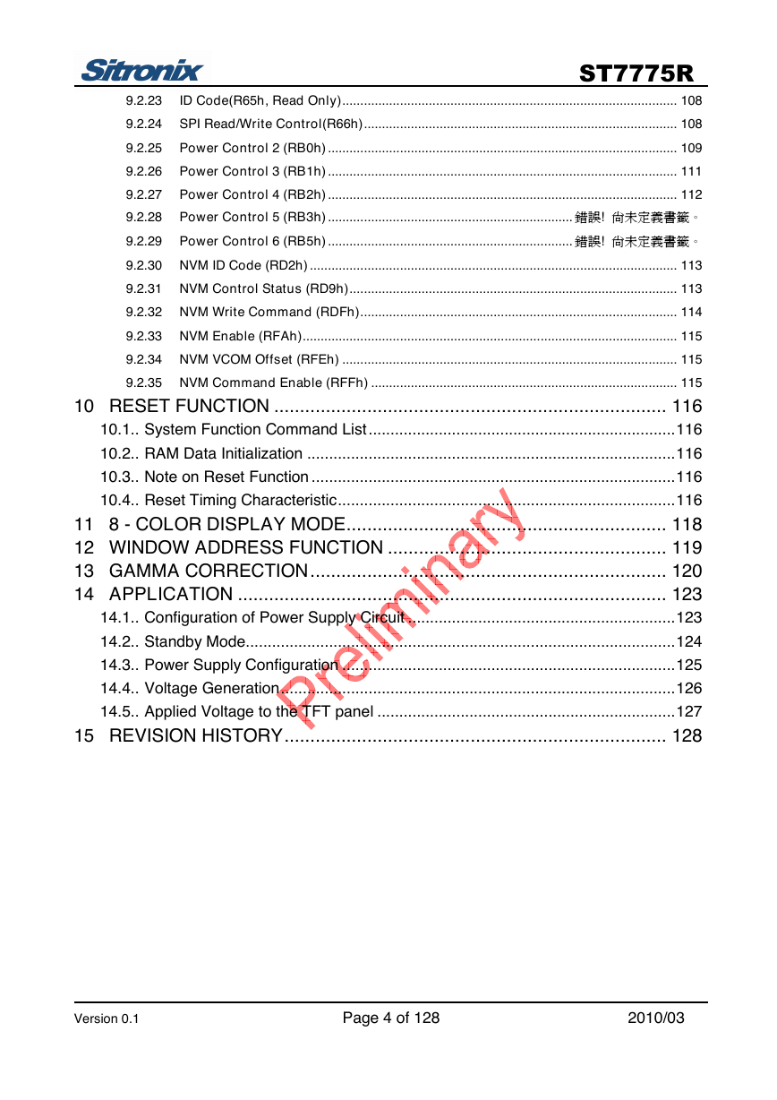
ID Code(R65h, Read Only)............................................................................................. 108
9.2.23
9.2.24 SPI Read/Write Control(R66h)....................................................................................... 108
9.2.25 Power Control 2 (RB0h) ................................................................................................. 109
9.2.26 Power Control 3 (RB1h) ................................................................................................. 111
9.2.27 Power Control 4 (RB2h) ................................................................................................. 112
9.2.28 Power Control 5 (RB3h) .................................................................... 錯誤! 尚未定義書籤。
9.2.29 Power Control 6 (RB5h) .................................................................... 錯誤! 尚未定義書籤。
9.2.30 NVM ID Code (RD2h) ...................................................................................................... 113
9.2.31 NVM Control Status (RD9h)........................................................................................... 113
9.2.32 NVM Write Command (RDFh)........................................................................................ 114
9.2.33 NVM Enable (RFAh)........................................................................................................ 115
9.2.34 NVM VCOM Offset (RFEh) ............................................................................................. 115
9.2.35 NVM Command Enable (RFFh) ..................................................................................... 115
10 RESET FUNCTION ............................................................................ 116
10.1.. System Function Command List......................................................................116
10.2.. RAM Data Initialization ....................................................................................116
10.3.. Note on Reset Function ...................................................................................116
10.4.. Reset Timing Characteristic.............................................................................116
11 8 - COLOR DISPLAY MODE.............................................................. 118
12 WINDOW ADDRESS FUNCTION ...................................................... 119
13 GAMMA CORRECTION..................................................................... 120
14 APPLICATION ................................................................................... 123
14.1.. Configuration of Power Supply Circuit .............................................................123
14.2.. Standby Mode..................................................................................................124
14.3.. Power Supply Configuration ............................................................................125
14.4.. Voltage Generation..........................................................................................126
14.5.. Applied Voltage to the TFT panel ....................................................................127
15 REVISION HISTORY.......................................................................... 128
Version 0.1 Page 4 of 128 2010/03
�
ST7775R
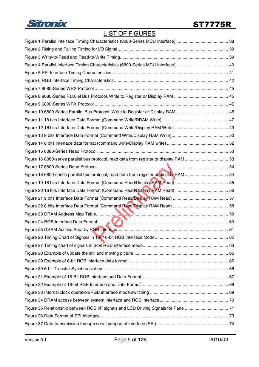
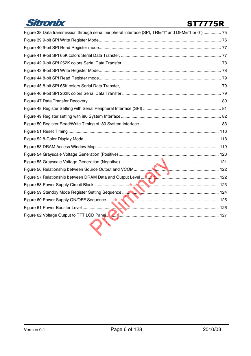
LIST OF FIGURES
Figure 1 Parallel Interface Timing Characteristics (8080-Series MCU Interface) ........................................... 38
Figure 2 Rising and Falling Timing for I/O Signal............................................................................................ 39
Figure 3 Write-to-Read and Read-to-Write Timing.......................................................................................... 39
Figure 4 Parallel Interface Timing Characteristics (6800-Series MCU Interface) ........................................... 40
Figure 5 SPI Interface Timing Characteristics................................................................................................. 41
Figure 6 RGB Interface Timing Characteristics............................................................................................... 42
Figure 7 8080-Series WRX Protocol ............................................................................................................... 45
Figure 8 8080-Series Parallel Bus Protocol, Write to Register or Display RAM ............................................. 45
Figure 9 6800-Series WRX Protocol ............................................................................................................... 46
Figure 10 6800-Series Parallel Bus Protocol, Write to Register or Display RAM ........................................... 46
Figure 11 18 bits Interface Data Format (Command Write/DRAM Write) ....................................................... 47
Figure 12 16 bits Interface Data Format (Command Write/Display RAM Write)............................................. 49
Figure 13 9 bits Interface Data Format (Command Write/Display RAM Write)............................................... 50
Figure 14 8 bits interface data format (command write/Display RAM write) ................................................... 52
Figure 15 8080-Series Read Protocol ............................................................................................................. 53
Figure 16 8080-series parallel bus protocol, read data from register or display RAM .................................... 53
Figure 17 6800-Series Read Protocol ............................................................................................................. 54
Figure 18 6800-series parallel bus protocol, read data from register or display RAM .................................... 54
Figure 19 18 bits Interface Data Format (Command Read/Display RAM Read) ............................................ 55
Figure 20 16 bits Interface Data Format (Command Read/Display RAM Read) ............................................ 56
Figure 21 9 bits Interface Data Format (Command Read/Display RAM Read) .............................................. 57
Figure 22 8 bits Interface Data Format (Command Read/Display RAM Read) .............................................. 58
Figure 23 DRAM Address Map Table.............................................................................................................. 59
Figure 24 RGB Interface Data Format............................................................................................................. 60
Figure 25 DRAM Access Area by RGB Interface............................................................................................ 61
Figure 26 Timing Chart of Signals in 18-/16-bit RGB Interface Mode............................................................. 62
Figure 27 Timing chart of signals in 6-bit RGB interface mode....................................................................... 63
Figure 28 Example of update the still and moving picture............................................................................... 65
Figure 29 Example of 6-bit RGB interface data format ................................................................................... 66
Figure 30 6-bit Transfer Synchronization ........................................................................................................ 66
Figure 31 Example of 16-Bit RGB Interface and Data Format........................................................................ 67
Figure 32 Example of 18-bit RGB Interface and Data Format ........................................................................ 68
Figure 33 Internal clock operation/RGB interface mode switching ................................................................. 69
Figure 34 DRAM access between system interface and RGB interface......................................................... 70
Figure 35 Relationship between RGB I/F signals and LCD Driving Signals for Pane .................................... 71
Figure 36 Data Format of SPI Interface........................................................................................................... 73
Figure 37 Data transmission through serial peripheral interface (SPI) ........................................................... 74
Version 0.1 Page 5 of 128 2010/03
�
ST7775R
Figure 38 Data transmission through serial peripheral interface (SPI, TRI=”1” and DFM=”1 or 0”) ............... 75
Figure 39 9-bit SPI Write Register Mode......................................................................................................... 76
Figure 40 9-bit SPI Read Register mode......................................................................................................... 77
Figure 41 9-bit SPI 65K colors Serial Data Transfer, ...................................................................................... 77
Figure 42 9-bit SPI 262K colors Serial Data Transfer ..................................................................................... 78
Figure 43 8-bit SPI Write Register Mode......................................................................................................... 78
Figure 44 8-bit SPI Read Register mode......................................................................................................... 79
Figure 45 8-bit SPI 65K colors Serial Data Transfer, ...................................................................................... 79
Figure 46 8-bit SPI 262K colors Serial Data Transfer ..................................................................................... 79
Figure 47 Data Transfer Recovery .................................................................................................................. 80
Figure 48 Register Setting with Serial Peripheral Interface (SPI) ................................................................... 81
Figure 49 Register setting with i80 System Interface ...................................................................................... 82
Figure 50 Register Read/Write Timing of i80 System Interface ...................................................................... 83
Figure 51 Reset Timing ................................................................................................................................. 116
Figure 52 8-Color Display Mode.................................................................................................................... 118
Figure 53 DRAM Access Window Map ......................................................................................................... 119
Figure 54 Grayscale Voltage Generation (Positive) ...................................................................................... 120
Figure 55 Grayscale Voltage Generation (Negative) .................................................................................... 121
Figure 56 Relationship between Source Output and VCOM......................................................................... 122
Figure 57 Relationship between DRAM Data and Output Level ................................................................... 122
Figure 58 Power Supply Circuit Block ........................................................................................................... 123
Figure 59 Standby Mode Register Setting Sequence ................................................................................... 124
Figure 60 Power Supply ON/OFF Sequence ................................................................................................ 125
Figure 61 Power Booster Level ..................................................................................................................... 126
Figure 62 Voltage Output to TFT LCD Panel ................................................................................................ 127
Version 0.1 Page 6 of 128 2010/03
�
ST7775R
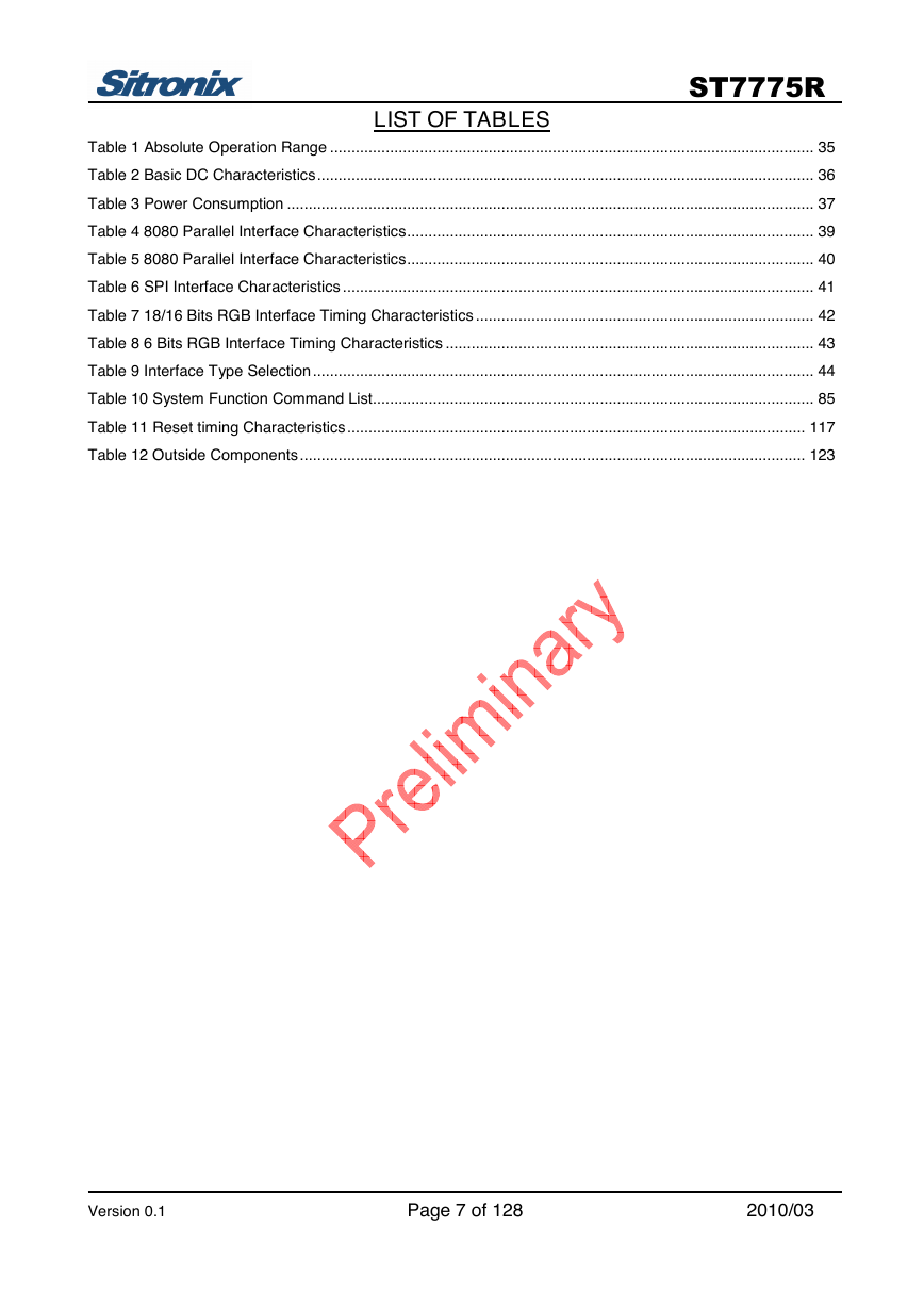
LIST OF TABLES
Table 1 Absolute Operation Range ................................................................................................................. 35
Table 2 Basic DC Characteristics.................................................................................................................... 36
Table 3 Power Consumption ........................................................................................................................... 37
Table 4 8080 Parallel Interface Characteristics............................................................................................... 39
Table 5 8080 Parallel Interface Characteristics............................................................................................... 40
Table 6 SPI Interface Characteristics .............................................................................................................. 41
Table 7 18/16 Bits RGB Interface Timing Characteristics ............................................................................... 42
Table 8 6 Bits RGB Interface Timing Characteristics ...................................................................................... 43
Table 9 Interface Type Selection..................................................................................................................... 44
Table 10 System Function Command List....................................................................................................... 85
Table 11 Reset timing Characteristics........................................................................................................... 117
Table 12 Outside Components...................................................................................................................... 123
Version 0.1 Page 7 of 128 2010/03
�
ST7775R
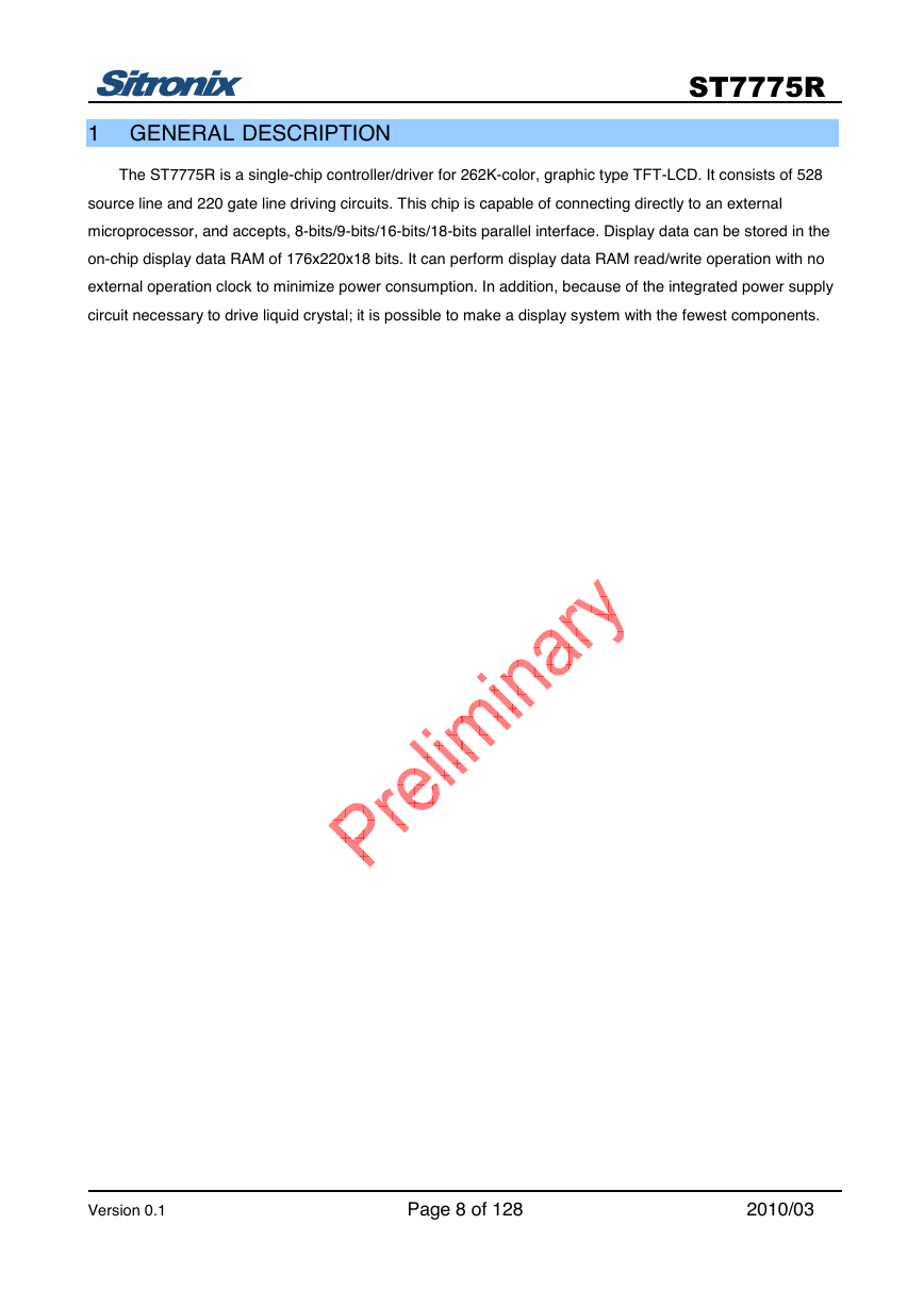
1 GENERAL DESCRIPTION
The ST7775R is a single-chip controller/driver for 262K-color, graphic type TFT-LCD. It consists of 528
source line and 220 gate line driving circuits. This chip is capable of connecting directly to an external
microprocessor, and accepts, 8-bits/9-bits/16-bits/18-bits parallel interface. Display data can be stored in the
on-chip display data RAM of 176x220x18 bits. It can perform display data RAM read/write operation with no
external operation clock to minimize power consumption. In addition, because of the integrated power supply
circuit necessary to drive liquid crystal; it is possible to make a display system with the fewest components.
Version 0.1 Page 8 of 128 2010/03
�



 2023年江西萍乡中考道德与法治真题及答案.doc
 2012年重庆南川中考生物真题及答案.doc
 2013年江西师范大学地理学综合及文艺理论基础考研真题.doc
 2020年四川甘孜小升初语文真题及答案I卷.doc
 2020年注册岩土工程师专业基础考试真题及答案.doc
 2023-2024学年福建省厦门市九年级上学期数学月考试题及答案.doc
 2021-2022学年辽宁省沈阳市大东区九年级上学期语文期末试题及答案.doc
 2022-2023学年北京东城区初三第一学期物理期末试卷及答案.doc
 2018上半年江西教师资格初中地理学科知识与教学能力真题及答案.doc
 2012年河北国家公务员申论考试真题及答案-省级.doc
 2020-2021学年江苏省扬州市江都区邵樊片九年级上学期数学第一次质量检测试题及答案.doc
 2022下半年黑龙江教师资格证中学综合素质真题及答案.doc