Foreword
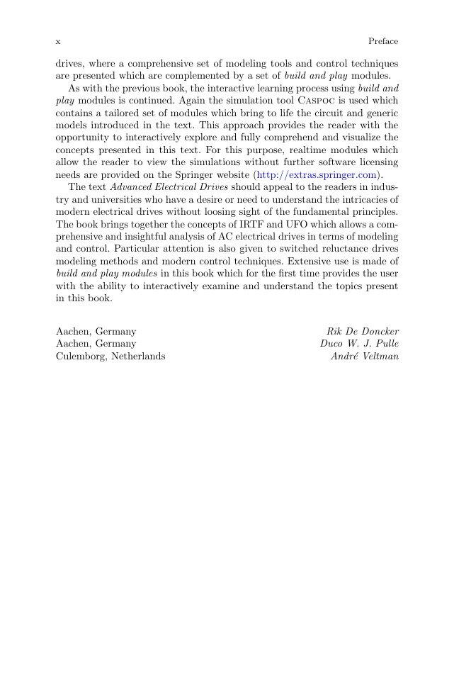
Preface
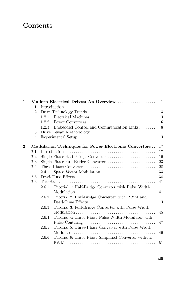
Contents
Chapter 1
Modern Electrical Drives: An Overview
1.1 Introduction
1.2 Drive Technology Trends
1.2.1 Electrical Machines
1.2.2 Power Converters
1.2.3 Embedded Control and Communication Links
1.3 Drive Design Methodology
1.4 Experimental Setup
Chapter 2
Modulation for Power
Electronic Converters
2.1 Introduction
2.2 Single-Phase Half-Bridge Converter
2.3 Single-Phase Full-Bridge Converter
2.4 Three-Phase Converter
2.4.1 Space Vector Modulation
2.5 Dead-Time Effects
2.6 Tutorials
2.6.1 Tutorial 1: Half-Bridge Converter with Pulse Width Modulation
2.6.2 Tutorial 2: Half-Bridge Converter with PWM and Dead-Time Effects
2.6.3 Tutorial 3: Full-Bridge Converter with Pulse Width Modulation
2.6.4 Tutorial 4: Three-Phase Pulse Width Modulator with Pulse Centering
2.6.5 Tutorial 5: Three-Phase Converter with Pulse Width Modulator
2.6.6 Tutorial 6: Three-Phase Simplified Converter without PWM
Chapter 3
Current Control of Generalized Load
3.1 Current Control of Single-Phase Load
3.1.1 Hysteresis Current Control
3.1.2 Model Based Current Control
3.1.3 Augmented Model Based Current Control
3.2 Current Control of a Three-Phase Load
3.2.1 Three-Phase Hysteresis Current Control
3.2.2 Model Based Three-Phase Current Control
3.2.3 Augmented Three-Phase Model Based Current Control
3.2.4 Frequency Spectrum of Hysteresis and Model Based Current Controllers
3.3 Tutorials
3.3.1 Tutorial 1: Single-Phase Hysteresis Current Control
3.3.2 Tutorial 2: Single-Phase Model Based Current Control
3.3.3 Tutorial 3: Three-Phase Box Method Type Hysteresis Current Control
3.3.4 Tutorial 4: Three-Phase Model Based Current Control
3.3.5 Tutorial 5: Three-Phase Model Based Current Control without PWM, Using Simplified Approach
Chapter 4
Drive Principles
4.1 ITF and IRTF Concepts
4.2 Electromagnetic Torque Control Principles
4.2.1 DC Machine
4.2.2 Synchronous Machine
4.2.3 Induction Machine
4.3 Drive Dynamics
4.3.1Linear and Rotational Motion
4.3.2 Rotational to Translational Transmission
4.3.3 Gear Transmission
4.3.4 Dynamic Model of a Drive Train
4.4 Shaft Speed Control Loop Design Principles
4.5 Tutorials
4.3.1 Tutorial 1: Elementary Synchronous Drive
4.3.2 Tutorial 2: Elementary Asynchronous (Induction) Drive
4.3.3 Tutorial 3: Elementary DC Drive
4.3.4 Tutorial 4: Drive Dynamics Example
4.3.5 Tutorial 5: Speed Control Loop Design Example
Chapter 5
Modeling and Control of DC Machines
5.1 Separately Excited, Current-Controlled DC Machine
5.1.1 Symbolic Model of the DC Machine
5.1.2 Generic Model DC Machine
5.2 Field-Oriented Machine Model
5.3 Control of Separately Excited DC Machines
5.3.1 Controller Concept
5.3.2 Operational Drive Boundaries
5.3.3 Use of Current Source IRTF Based Model
5.3.4 Use of a Voltage Source with a Model Based Current Control
5.4 Tutorials
5.4.1 Tutorial 1: Current Source Model of a Brushed DC Machine with Segmented Commutation Module
5.4.2 Tutorial 2: Modeling of a Current and Voltage Source Connected Brushed DC Motor
5.4.3 Tutorial 3: Current Source Connected Brushed DC Motor with Field Weakening Controller
5.4.5 Tutorial 4: DC Drive Operating under Model Based Current Control and a Field Weakening Controller
5.4.5 Tutorial 5: DC Drive with Model Based Current Control and Shaft Speed Control Loop
5.4.6 Tutorial 6: Experimental Results of DC Machine
Chapter 6
Synchronous Machine Modeling Concepts
6.1 Non-salient Machine
6.1.1 Symbolic Model of a Non-salient Machine
6.1.2 Generic Model
6.1.3 Rotor-Oriented Model: Non-salient Synchronous Machine
6.1.4 Steady-State Analysis
6.2 Salient Synchronous Machine
6.2.1 Generic Model
6.2.2 Rotor-Oriented Model of the Salient Synchronous Machine
6.2.3 Steady-State Analysis
6.3 Tutorials
6.3.1 Tutorial 1: Dynamic Model of a Non-salient Synchronous Machine
6.3.2 Tutorial 2: Steady-State Analysisof a Non-salient Synchronous Machine
6.3.3 Tutorial 3: Stator Flux Linkage Excited Dynamic Model of a Synchronous Machineto Demonstrate the Rotor Flux Oriented Concept
6.3.4 Tutorial 4: Dynamic Model of a Synchronous Machine with Adjustable Saliency
6.3.5 Tutorial 5: Steady-State Analysis of a Salient Synchronous Machine
Chapter 7
Control of Synchronous Machine Drives
7.1 Controller Principles
7.2 Control of Non-salient Synchronous Machines
7.2.1 Operation under Drive Limitations
7.2.2 Field Weakening Operation for PM Non-salient Drives
7.2.3 Field Weakening for PM Non-salient Drives, with Constant Stator Flux Linkage Control
7.2.4 Field Weakening for Electrically Excited Non-salient Drive, with Constant Stator Flux and Unity Power Factor Control
7.3 Control of Salient Synchronous Machines
7.4 Interfacing the Field-Oriented Control Module with a Current-Controlled Synchronous Machine
7.5 Interfacing the Field-Oriented Control Module with a Voltage-Source Connected Synchronous Machine
7.6 Tutorials
7.6.1 Tutorial 1: Non-salient Synchronous Drive
7.6.2 Tutorial 2: Non-salient Synchronous Drive, Constant Stator Flux Operation
7.6.3 Tutorial 3: Non-salient Synchronous Drive, Unity Power Factor Operation
7.6.4 Tutorial 4: Salient Synchronous Drive
7.6.5 Tutorial 5: PM Salient Synchronous Drivewith Model Based Current Control
7.6.6 Tutorial 6: Experimental Results of a PM Non-salient Synchronous Drive
Chapter 8
Induction Machine Modeling Concepts
8.1 Induction Machine with Squirrel-Cage Rotor
8.2 Zero Leakage Inductance Models of Induction Machines
8.2.1 IRTF Based Model of the Induction Machine
8.2.2 Field-Oriented Model
8.3 Machine Models with Leakage Inductances
8.3.1 Fundamental IRTF Based Model
8.3.2 Universal IRTF Based Model
8.3.2.1 Rotor Flux Based IRTF Model
8.3.2.2 Stator Flux Based IRTF Model
8.3.3 Universal Stationary Frame Oriented Model
8.3.4 Universal Field-Oriented (UFO) Model
8.3.4.1 Rotor Flux Oriented Model
8.3.4.2 Stator Flux Oriented Model
8.3.5 Synchronous Frame Oriented Heyland diagram
8.3.6 Steady-State Analysis of Voltage-Source-Connected Induction Machines
8.4 Parameter Identification and Estimates for Stator and Rotor Flux Linkage Magnitude
8.5 Single-Phase Induction Machines
8.5.1Steady-State Analysis of Capacitor-Run Single-Phase Induction Machines
8.6 Tutorials
8.6.1 Tutorial 1: Simplified Induction Machine Model
8.6.2 Tutorial 2: Universal Induction Machine Model
8.6.3 Tutorial 3: Universal Stationary Oriented Induction Machine Model
8.6.4 Tutorial 4: Current Controlled Zero Leakage Flux Oriented Machine Model
8.6.5 Tutorial 5: Current Controlled Universal Field Oriented (UFO) Model
8.6.6 Tutorial 6: Parameter Estimation Using Name Plate Data and Known Stator Resistance
8.6.7 Tutorial 7: Grid Connected Induction Machine
8.6.8 Tutorial 8: Steady State Characteristics, Grid Connected Induction Machine
8.6.9Tutorial 9: Grid Connected Single-Phase Induction Machine
Chapter 9
Control of Induction Machine Drives
9.1 Voltage-to-Frequency (V/f) Control
9.1.1 Simple V/f Speed Controller
9.1.2 V/f Torque Controller with Shaft Speed Sensor
9.2 Field-Oriented Control
9.2.1 Controller Principle
9.2.2 Controller Structure
9.2.3 UFO Module Structure
9.2.4 IFO Using Measured Shaft Speed or Shaft Angle
9.2.5 DFO with Air-Gap Flux Sensors
9.2.6 DFO with Sensor Coils
9.2.7 DFO with Voltage and Current Transducers
9.2.8 DFO with Current and Shaft Speed Transducers
9.3 Operational Drive Boundaries for Rotor Flux Oriented Control
9.4 Field Weakening for Rotor Flux Oriented IM Drives
9.5 Interfacing the Field-Oriented Controller with a Current-Controlled Induction Machine
9.6 Interfacing the Field-Oriented Controller with a Voltage-Source-Connected Induction Machine
9.7 Tutorials
9.7.1Tutorial 1: Simplified V/f Drive
9.7.2 Tutorial 2: V/f Drive with Shaft Speed Sensor
9.7.3 Tutorial 3: Universal Field-Oriented (UFO) Control with a Current Source Based Machine Model and Known Shaft Angle
9.7.4 Tutorial 4: Induction Machine Drive with UFO Controller and Model-Based Current Control
9.7.5 Tutorial 5: Rotor Flux Oriented Induction Machine Drive with UFO Controller and Field Weakening Controller
9.7.6 Tutorial 6: Experimental Results of an Induction Machine with UFO Controller
Chapter 10
Switched Reluctance Drive Systems
10.1 Basic Machine Concepts
10.2 Operating Principles
10.2.1 Single-Phase Motor Concept
10.2.2 Torque Production and Energy Conversion Principles
10.2.3 Single-Phase Switched Reluctance Machine:A Linear Example
10.2.4 Switched Reluctance Modeling Concepts
10.2.5 Representation of the Magnetization Characteristics
10.2.6 Converter and Control Concepts
10.2.7 Example of Low and High Speed Drive Operation
10.3 Multi-Phase Machines
10.3.1 Converter Concepts
10.4 Control of Switched Reluctance Drives
10.4.1 Drive Characteristics and Operating Range
10.4.2 Drive Operational Aspects
10.4.3 Direct Instantaneous Torque Control (DITC)
10.5 Switched Reluctance Demonstration Machine
10.6 Tutorials
10.6.1 Tutorial 1: Analysis of a Linear SR Machine, with Current Excitation
10.6.2 Tutorial 2: Non-linear SR Machine,with Voltage Excitation and Hysteresis Current Controller
10.6.3 Tutorial 3: Non-linear SR Machine,with Voltage Excitation and PWM Controller
10.6.4 Tutorial 4: Four-Phase Non-linear SR Model, with Voltage Excitation and Hysteresis Control
10.6.6 Tutorial 5: Four-Phase Non-linear SR Model, with Voltage Excitation and Direct Instantaneous Torque Control (DITC)
References
Abbreviations
List of symbols
List of indices
Index



 2023年江西萍乡中考道德与法治真题及答案.doc
 2012年重庆南川中考生物真题及答案.doc
 2013年江西师范大学地理学综合及文艺理论基础考研真题.doc
 2020年四川甘孜小升初语文真题及答案I卷.doc
 2020年注册岩土工程师专业基础考试真题及答案.doc
 2023-2024学年福建省厦门市九年级上学期数学月考试题及答案.doc
 2021-2022学年辽宁省沈阳市大东区九年级上学期语文期末试题及答案.doc
 2022-2023学年北京东城区初三第一学期物理期末试卷及答案.doc
 2018上半年江西教师资格初中地理学科知识与教学能力真题及答案.doc
 2012年河北国家公务员申论考试真题及答案-省级.doc
 2020-2021学年江苏省扬州市江都区邵樊片九年级上学期数学第一次质量检测试题及答案.doc
 2022下半年黑龙江教师资格证中学综合素质真题及答案.doc