logo资料库

Saber仿真开关电源设计.pdf

第1页 / 共32页
第2页 / 共32页
第3页 / 共32页
第4页 / 共32页
第5页 / 共32页
第6页 / 共32页
第7页 / 共32页
第8页 / 共32页
资料共32页,剩余部分请下载后查看
Power Converter Design Using the Saber Simulator
A Step-By-Step Guide to the Design of a
Two-Switch, Voltage-Mode, Forward Converter
Using the Saber Simulator
1.0 Scope of Document
2.0 Specifications
2.1 Input Specifications
2.2 Output Specifications
2.3 Other Specifications
3.0 Step-By-Step Design Process
3.1 Open Loop Design
3.1.1 Define the Duty Cycle and Turns Ratio of the Transformer
3.1.2 Design the Rectifier and Filter Capacitor (Optional Section)
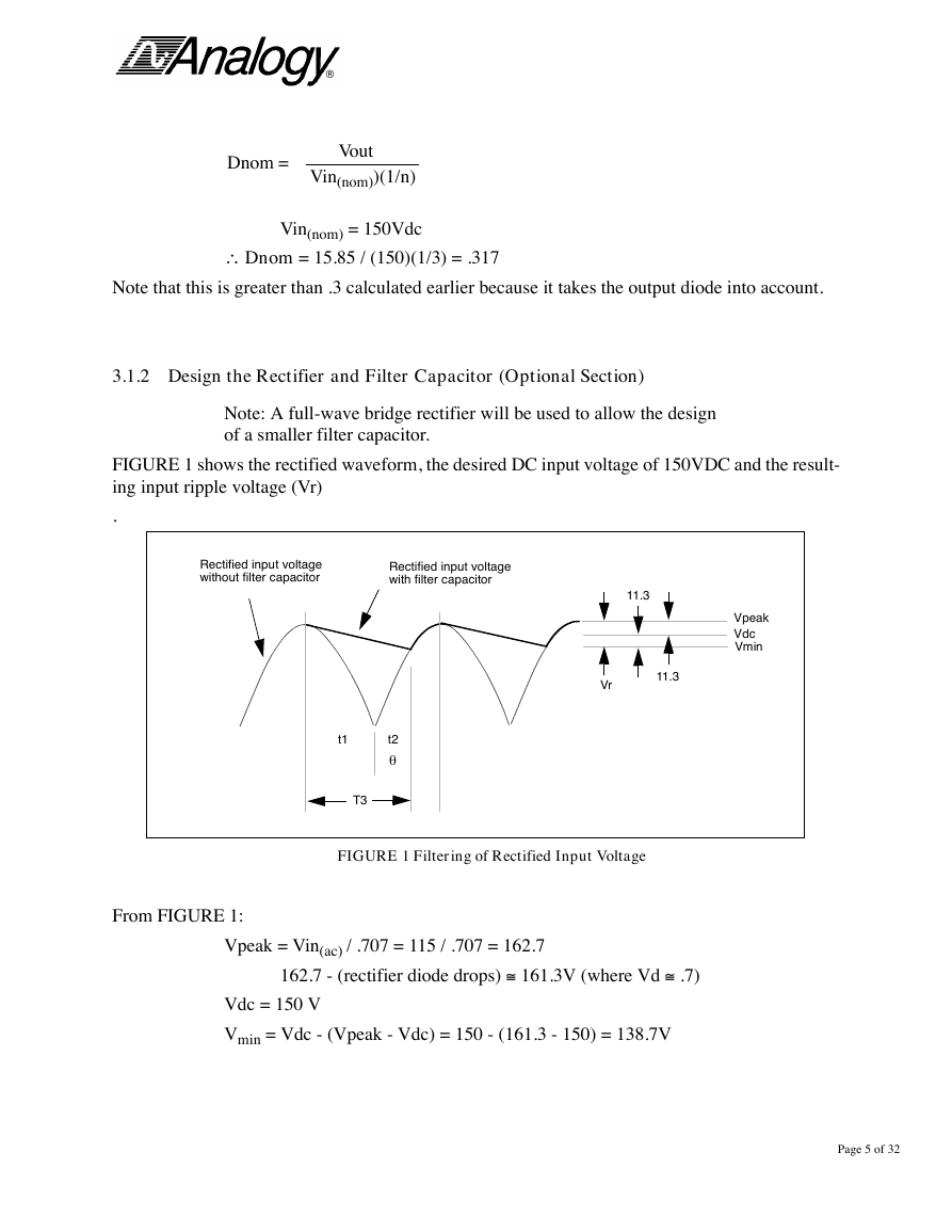
FIGURE 1 Filtering of Rectified Input Voltage
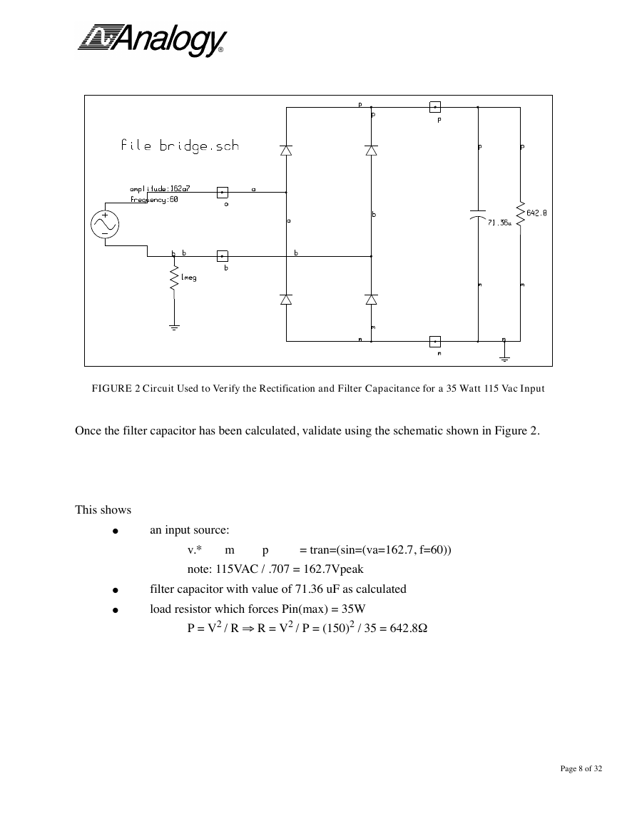
FIGURE 2 Circuit Used to Verify the Rectification and Filter Capacitance for a 35 Watt 115 Vac Input
3.1.2.1 Validate the Rectifier and Filter Capacitor using Saber
FIGURE 3 Voltage Across the Input Filter Capacitor
3.1.3 Output Filter Design
3.1.3.1 Inductor Design
FIGURE 4 Current through the Filter Inductor
FIGURE 5 Current Through Filter Inductor
3.1.3.2 Capacitor Design
3.1.4 Validate the Open Loop Design using Saber
FIGURE 6 Open Loop Configuration of the Forward Converter
FIGURE 7 Open Loop Simulation Results
FIGURE 8 Inductor Ripple Current
FIGURE 9 Output Ripple voltage
3.2 Compensator Design using an Averaged Model
FIGURE 10 Averaged Configuration of the Forward Converter
3.2.1 Validate the Averaged Model using Saber
FIGURE 11 Averaged Model vs. Switching Circuit
FIGURE 12 Inductor Current (Switching vs. Averaged)
FIGURE 13 Output Voltage (Switching vs. Averaged)
3.2.2 Open-Loop AC Analysis
FIGURE 14 Phase/Gain plot of the Control-to-Output transfer function
3.2.3 Designing the Compensation Circuit
FIGURE 15 Type 10 Compensation Network
3.2.4 Validate the Compensator Design using Saber
FIGURE 16 Phase/Gain plot (Post Compensator Design)
3.2.5 Validate the Closed Loop Parameters using Saber
FIGURE 17 Output Voltage
FIGURE 18 Duty Cycle and Control Voltage as solved by the system
3.3 Modulator Design and Closed Loop Simulation
FIGURE 19 Close Loop Configuration of the Forward Converter
FIGURE 20 Modulation Circuit Waveforms
3.3.1 Validate the Modulator Design using Saber
FIGURE 21 Validation of the Modulation Circuitry
FIGURE 22 Mixed Digital and Analog Waveforms of the Modulator
3.3.2 Validate the Closed Loop Design using Saber
FIGURE 23 Closed Loop Simulation using the Switching Circuitry
FIGURE 24 Duty cycle le results from the measurement model
3.4 Final Component Level Design
FIGURE 25 Component Level Design/Modeling of the Forward Converter
FIGURE 26 Error Amplifier’s inverting input & output, and ramp waveform from the 1825 PWM model
FIGURE 27 Output voltage and filer Inductor current waveforms
® Power Converter Design Using the Saber Simulator A Step-By-Step Guide to the Design of a Two-Switch, Voltage-Mode, Forward Converter Using the Saber Simulator By Steve Chwirka Analogy, Inc. Beaverton, Oregon (503) 626-9700 Page 1 of 32
® Table of Content 1.0 Scope of Document 3 2.0 Specifications 3 2.1 Input Specifications 3 2.2 Output Specifications 3 2.3 Other Specifications 3 3.0 Step-By-Step Design Process 4 3.1 Open Loop Design 4 3.1.1 Define the Duty Cycle and Turns Ratio of the Transformer 4 3.1.2 Design the Rectifier and Filter Capacitor (Optional Section) 5 Validate the Rectifier and Filter Capacitor using Saber 9 3.1.3 Output Filter Design 10 Inductor Design 10 Capacitor Design 11 3.1.4 Validate the Open Loop Design using Saber 11 3.2 Compensator Design using an Averaged Model 15 3.2.1 Validate the Averaged Model using Saber 16 3.2.2 Open-Loop AC Analysis 18 3.2.3 Designing the Compensation Circuit 18 3.2.4 Validate the Compensator Design using Saber 21 3.2.5 Validate the Closed Loop Parameters using Saber 21 3.3 Modulator Design and Final Closed Loop Simulation 23 3.3.1 Validate the Modulator Design using Saber 25 3.3.2 Validate the Closed Loop Design using Saber 27 3.4 Final Component Level Design 29 Page 2 of 32
® 1.0 Scope of Document This engineering document will guide the reader through the step-by-step design of a two switch, voltage mode, forward power converter using the Saber Simulator. In the process, we will describe typical design considerations and problems and how to overcome them. Validation of each step in the design process will be performed using Saber. 2.0 Specifications The following specifications will be used to design the power converter. 2.1 Input Specifications Line Input Pin(max) = Pout(max) = 30/.85 Eff 150Vdc, – 35 Watts 6V 2.2 Output Specifications Vout Vout(ripple) Iout Iout(ripple) Pout(max) = (15V)(2A) 15Vdc 25mV p-p 50mA to 2A £ 100mA p-p 30 Watts 2.3 Other Specifications Efficiency Switching Frequency 85% 200KHz (derived) Page 3 of 32 £ ‡
® 3.0 Step-By-Step Design Process This section details the steps necessary to design the power converter. 3.1 Open Loop Design 3.1.1 Define the Duty Cycle and Turns Ratio of the Transformer The basic relationship in a forward converter is Vout @ where (Vin)(1 / n)(D) Vout =dc output voltage n = turns ratio = np / ns D = duty cycle Given that Vout = 15VDC and Vin = 150 VDC, we see that (1 / n)(D) must equal 0.1 i.e. 15 = (150)(.1) The duty cycle of a forward converter should not exceed .5. Therefore we will choose a value which is between 0 and 0.5. In this example we choose D = 0.3, approximately the midpoint of the range. Therefore we know (1 / n)(D) = .1 or 1 / n = .1 / D = .1 / .3 = 1/3 so n = 3 The next step is to define the maximum and nominal duty cycle which include the output diode losses. These values will be needed for future calculations. Dmax = Vout (Vin(min))(1/n) n = turns ration = np / ns = 3 Vin(min) = 144 (per specifications) Vout = 15V + (output diode losses @ .85V) = 15.85V Dmax = 15.85 / (144)(1/3) = .3302 Note that this is less than .5, the maximum duty cycle allowed in a forward converter. Page 4 of 32 \
® Dnom = Vout Vin(nom))(1/n) Vin(nom) = 150Vdc Dnom = 15.85 / (150)(1/3) = .317 Note that this is greater than .3 calculated earlier because it takes the output diode into account. 3.1.2 Design the Rectifier and Filter Capacitor (Optional Section) Note: A full-wave bridge rectifier will be used to allow the design of a smaller filter capacitor. FIGURE 1 shows the rectified waveform, the desired DC input voltage of 150VDC and the result- ing input ripple voltage (Vr) . Rectified input voltage without filter capacitor Rectified input voltage with filter capacitor 11.3 Vr 11.3 Vpeak Vdc Vmin t1 t2 T3 FIGURE 1 Filtering of Rectified Input Voltage From FIGURE 1: Vpeak = Vin(ac) / .707 = 115 / .707 = 162.7 162.7 - (rectifier diode drops) @ 161.3V (where Vd @ Vdc = 150 V Vmin = Vdc - (Vpeak - Vdc) = 150 - (161.3 - 150) = 138.7V .7) Page 5 of 32 \ q
® The input filter capacitor value can be found in two ways Input Capacitor Value - Method 1 C = (Idc)(T3) / Vr Idc = Pin(max) / Vdc = 35W / 150V = .233A Vr = (2)(Vpeak-Vdc) = (2)(11.3) = 22.6V T3 = Time the capacitor must deliver its energy to the circuit Solving for T3: T3 = t1 + t2 t1 = (1/4)(1/f) where f = input frequency = 60Hz = (1/4)(1/60) = 4.166 msec Note: Most text books at this point assume that the input ripple is small and therefore that t2 @ t1 which would yield T3 = 4.166 msec + 4.166 msec = 8.33 msec However, this is not the case in many designs. Therefore we need to use the following equations to calculate t2: Referring to FIGURE 1: Vmin = Vpeak(Sinq) Sin-1 Vmin = Vpeak = Sin-1(138.7 / 161.3) = 59.3o We know that 180o (1/2) (1/f) = t2 where f = input freq = 60Hz \ t2 = (q )(1/2)(1/f) = (59.3)(1/2)(1/60) / 180o 180o t2 = 2.745 msec Page 6 of 32 q q q
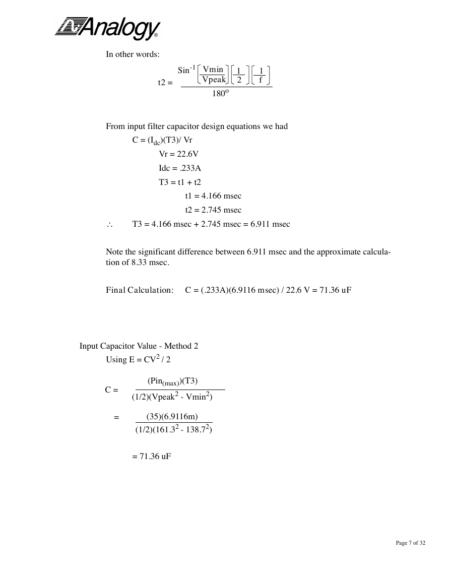
® In other words: t2 = Sin-1 Vmin Vpeak 180o 1 2 1 f From input filter capacitor design equations we had C = (Idc)(T3)/ Vr Vr = 22.6V Idc = .233A T3 = t1 + t2 t1 = 4.166 msec t2 = 2.745 msec T3 = 4.166 msec + 2.745 msec = 6.911 msec Note the significant difference between 6.911 msec and the approximate calcula- tion of 8.33 msec. Final Calculation: C = (.233A)(6.9116 msec) / 22.6 V = 71.36 uF Input Capacitor Value - Method 2 Using E = CV2 / 2 C = (Pin(max))(T3) (1/2)(Vpeak2 - Vmin2) = (35)(6.9116m) (1/2)(161.32 - 138.72) = 71.36 uF Page 7 of 32 \
® FIGURE 2 Circuit Used to Verify the Rectification and Filter Capacitance for a 35 Watt 115 Vac Input Once the filter capacitor has been calculated, validate using the schematic shown in Figure 2. This shows l l l an input source: m = tran=(sin=(va=162.7, f=60)) v.* note: 115VAC / .707 = 162.7Vpeak p filter capacitor with value of 71.36 uF as calculated load resistor which forces Pin(max) = 35W P = V2 / R R = V2 / P = (150)2 / 35 = 642.8W Page 8 of 32
分享到:
收藏