Drive for better vision
Mobile Industry Processor Interface
D-PHY and DSI
Introduction
March 2010
�
What is MIPI?
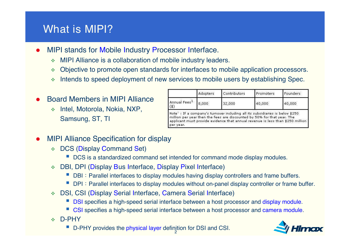
� MIPI stands for Mobile Industry Processor Interface.
MIPI Alliance is a collaboration of mobile industry leaders.
Objective to promote open standards for interfaces to mobile application processors.
Intends to speed deployment of new services to mobile users by establishing Spec.
� Board Members in MIPI Alliance
Intel, Motorola, Nokia, NXP,
Samsung, ST, TI
� MIPI Alliance Specification for display
DCS (Display Command Set)
� DCS is a standardized command set intended for command mode display modules.
DBI, DPI (Display Bus Interface, Display Pixel Interface)
� DBI:Parallel interfaces to display modules having display controllers and frame buffers.
� DPI:Parallel interfaces to display modules without on-panel display controller or frame buffer.
DSI, CSI (Display Serial Interface, Camera Serial Interface)
� DSI specifies a high-speed serial interface between a host processor and display module.
� CSI specifies a high-speed serial interface between a host processor and camera module.
D-PHY
Himax Proprietary & Confidential
� D-PHY provides the physical layer definition for DSI and CSI.
2
�
D-PHY Layer Definitions - 1
Himax Proprietary & Confidential
3
DCS Spec.
DSI Spec.
D-PHY Spec.
�
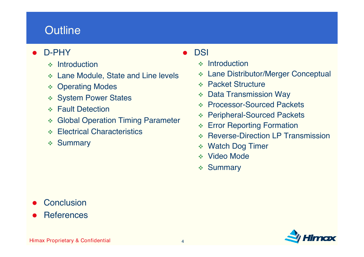
Outline
� D-PHY
Introduction
Lane Module, State and Line levels
Operating Modes
System Power States
Fault Detection
Global Operation Timing Parameter
Electrical Characteristics
Summary
� DSI
Introduction
Lane Distributor/Merger Conceptual
Packet Structure
Data Transmission Way
Processor-Sourced Packets
Peripheral-Sourced Packets
Error Reporting Formation
Reverse-Direction LP Transmission
Watch Dog Timer
Video Mode
Summary
� Conclusion
� References
Himax Proprietary & Confidential
4
�
Introduction for D-PHY
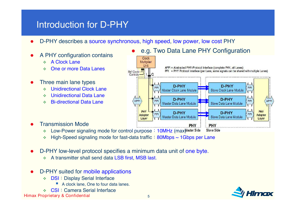
� D-PHY describes a source synchronous, high speed, low power, low cost PHY
� e.g. Two Data Lane PHY Configuration
� A PHY configuration contains
A Clock Lane
One or more Data Lanes
� Three main lane types
Unidirectional Clock Lane
Unidirectional Data Lane
Bi-directional Data Lane
� Transmission Mode
Low-Power signaling mode for control purpose:10MHz (max)
High-Speed signaling mode for fast-data traffic:80Mbps ~ 1Gbps per Lane
� D-PHY low-level protocol specifies a minimum data unit of one byte.
A transmitter shall send data LSB first, MSB last.
� D-PHY suited for mobile applications
DSI:Display Serial Interface
� A clock lane, One to four data lanes.
CSI:Camera Serial Interface
Himax Proprietary & Confidential
5
�
Lane Module
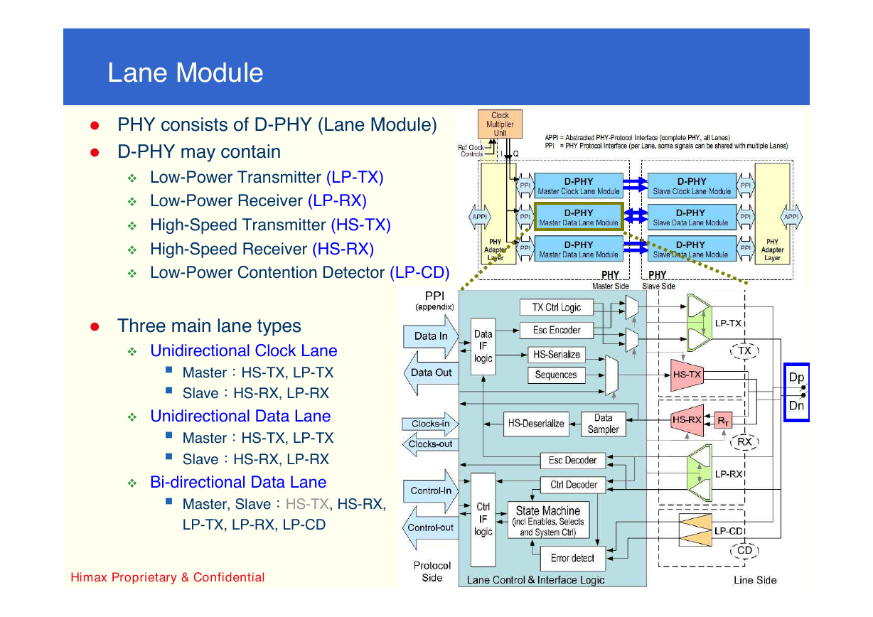
� PHY consists of D-PHY (Lane Module)
� D-PHY may contain
Low-Power Transmitter (LP-TX)
Low-Power Receiver (LP-RX)
High-Speed Transmitter (HS-TX)
High-Speed Receiver (HS-RX)
Low-Power Contention Detector (LP-CD)
� Three main lane types
Unidirectional Clock Lane
� Master:HS-TX, LP-TX
� Slave:HS-RX, LP-RX
Unidirectional Data Lane
� Master:HS-TX, LP-TX
� Slave:HS-RX, LP-RX
Bi-directional Data Lane
� Master, Slave:HS-TX, HS-RX,
LP-TX, LP-RX, LP-CD
Himax Proprietary & Confidential
6
�
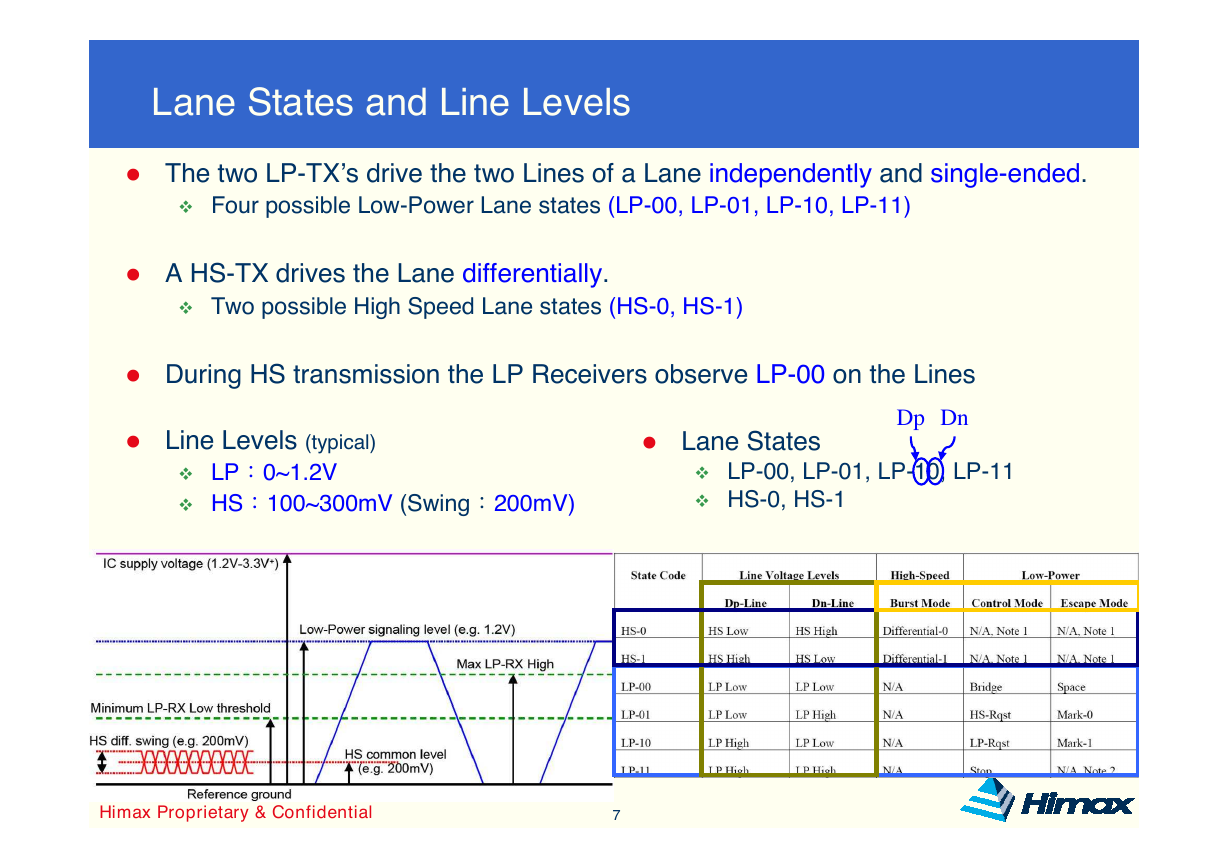
Lane States and Line Levels
� The two LP-TX’s drive the two Lines of a Lane independently and single-ended.
Four possible Low-Power Lane states (LP-00, LP-01, LP-10, LP-11)
� A HS-TX drives the Lane differentially.
Two possible High Speed Lane states (HS-0, HS-1)
� During HS transmission the LP Receivers observe LP-00 on the Lines
� Line Levels (typical)
� Lane States
Dp Dn
LP:0~1.2V
HS:100~300mV (Swing:200mV)
LP-00, LP-01, LP-10, LP-11
HS-0, HS-1
Himax Proprietary & Confidential
7
�
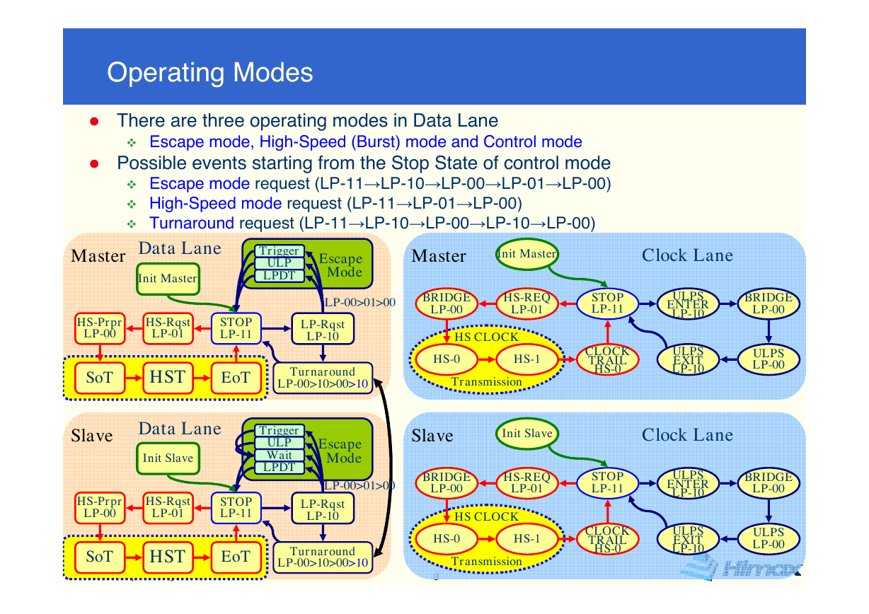
Operating Modes
� There are three operating modes in Data Lane
Escape mode, High-Speed (Burst) mode and Control mode
� Possible events starting from the Stop State of control mode
Escape mode request (LP-11→LP-10→LP-00→LP-01→LP-00)
High-Speed mode request (LP-11→LP-01→LP-00)
Turnaround request (LP-11→LP-10→LP-00→LP-10→LP-00)
Master
Data Lane
Init Master
Trigger
ULP
LPDT
Escape
Mode
Master
Init Master
Clock Lane
LP-00>01>00
BRIDGE
LP-00
HS-REQ
LP-01
STOP
LP-11
ULPS
ENTER
LP-10
BRIDGE
LP-00
HS-Prpr
LP-00
HS-Rqst
LP-01
STOP
LP-11
LP-Rqst
LP-10
SoT
HST
EoT
Turnaround
LP-00>10>00>10
HS CLOCK
HS-0
HS-1
Transmission
CLOCK
TRAIL
HS-0
ULPS
EXIT
LP-10
ULPS
LP-00
Slave
Data Lane
Init Slave
Trigger
ULP
Wait
LPDT
Slave
Init Slave
Clock Lane
Escape
Mode
LP-00>01>00
BRIDGE
LP-00
HS-REQ
LP-01
STOP
LP-11
ULPS
ENTER
LP-10
BRIDGE
LP-00
HS-Prpr
LP-00
HS-Rqst
LP-01
STOP
LP-11
SoT
HST
EoT
Himax Proprietary & Confidential
LP-Rqst
LP-10
Turnaround
LP-00>10>00>10
HS CLOCK
HS-0
HS-1
Transmission
8
CLOCK
TRAIL
HS-0
ULPS
EXIT
LP-10
ULPS
LP-00
�




 2023年江西萍乡中考道德与法治真题及答案.doc
 2012年重庆南川中考生物真题及答案.doc
 2013年江西师范大学地理学综合及文艺理论基础考研真题.doc
 2020年四川甘孜小升初语文真题及答案I卷.doc
 2020年注册岩土工程师专业基础考试真题及答案.doc
 2023-2024学年福建省厦门市九年级上学期数学月考试题及答案.doc
 2021-2022学年辽宁省沈阳市大东区九年级上学期语文期末试题及答案.doc
 2022-2023学年北京东城区初三第一学期物理期末试卷及答案.doc
 2018上半年江西教师资格初中地理学科知识与教学能力真题及答案.doc
 2012年河北国家公务员申论考试真题及答案-省级.doc
 2020-2021学年江苏省扬州市江都区邵樊片九年级上学期数学第一次质量检测试题及答案.doc
 2022下半年黑龙江教师资格证中学综合素质真题及答案.doc