CHANGES TO THIS EDITION
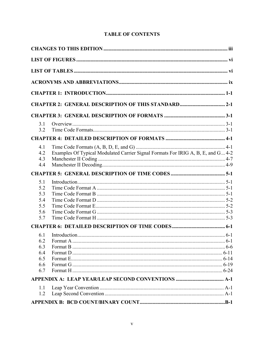
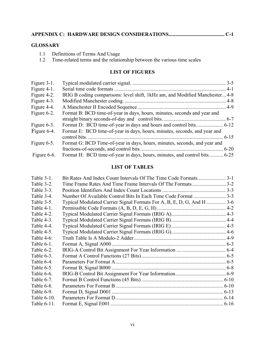
LIST OF FIGURES
LIST OF TABLES
INTRODUCTION
GENERAL DESCRIPTION OF THIS STANDARD
GENERAL DESCRIPTION OF FORMATS
3.1Overview
3.2Time Code Formats
3.2.1Pulse Rise Time. The specified pulse (dc level shift bit) rise time shall be obtained between the 10 and 90 percent amplitude points (see Appendix C).
3.2.2Jitter. The modulated code is defined as 1 percent at the carrier frequency. The dc level shift code is defined as the pulse-to-pulse variation at the 50 percent amplitude points on the leading edges of successive pulses or bits (see Appendix C
3.2.3Bit Rates and Index Count. Each pulse in a time code word/sub-word is called a bit. The "on-time" reference point for all bits is the leading edge of the bit. The repetition rate at which the bits occur is called the bit rate. Each bit has an as
3.2.4Time Frame, Time Frame Reference, and Time Frame Rates. A time code frame begins with a frame reference marker P0 (position identifier) followed by a reference bit Pr with each having duration equal to 0.8 of the index count interval of the resp
3.2.5Position Identifiers. Position identifiers have durations equal to 0.8 of the index count interval of the respective code. The leading edge of the position identifier P0 occurs one index count interval before the frame reference point Pr and the s
3.2.6Time Code Words. The two time code words employed in this standard are:
3.2.7BCD Time-of-Year Code Word. The BCD time-of-year and year code word consists of sub-words in days, hours, minutes, seconds, and year with fractions of a second in a BCD representation and time-of-day in SBS of day. The position identifiers precedi
3.2.8Control Functions. All time code formats reserve a set of bits known as control functions (CF) for the encoding of various control, identification, and other special purpose functions. The control bits may be programmed in any predetermined codi
3.2.9Index Markers. Index markers occur at each index count position, which is not assigned as a reference marker, position identifier, code, or control function bit. Each index marker bit has duration equal to 0.2 of the index count interval of the re
3.2.10Amplitude Modulated Carrier. A standard sine wave carrier frequency to be amplitude modulated by a time code is synchronized to have positive-going, zero-axis crossings coincident with the leading edges of the modulating code bits. A mark-to-spac
DETAILED DESCRIPTION OF FORMATS
4.1Time Code Formats (A, B, D, E, and G)
4.2Examples Of Typical Modulated Carrier Signal Formats For IRIG A, B, E, and G
4.3Manchester II Coding
4.4Manchester II Decoding
GENERAL DESCRIPTION OF TIME CODES
5.1Introduction
5.2Time Code Format A
5.3Time Code Format B
5.4Time Code Format D
5.5Time Code Format E
5.6Time Code Format G
5.7Time Code Format H
DETAILED DESCRIPTION OF TIME CODES
6.1Introduction
6.2Format A
6.3Format B
6.4Format D
6.5Format E
6.6Format G
6.7Format H
LEAP YEAR/LEAP SECOND CONVENTIONS
Leap Year Convention
Leap Second Convention
BCD COUNT/BINARY COUNT
HARDWARE DESIGN CONSIDERATIONS
1.1Definitions of Terms And Usage
1.2Time-related terms and the relationship between the various time scales.





 2023年江西萍乡中考道德与法治真题及答案.doc
 2012年重庆南川中考生物真题及答案.doc
 2013年江西师范大学地理学综合及文艺理论基础考研真题.doc
 2020年四川甘孜小升初语文真题及答案I卷.doc
 2020年注册岩土工程师专业基础考试真题及答案.doc
 2023-2024学年福建省厦门市九年级上学期数学月考试题及答案.doc
 2021-2022学年辽宁省沈阳市大东区九年级上学期语文期末试题及答案.doc
 2022-2023学年北京东城区初三第一学期物理期末试卷及答案.doc
 2018上半年江西教师资格初中地理学科知识与教学能力真题及答案.doc
 2012年河北国家公务员申论考试真题及答案-省级.doc
 2020-2021学年江苏省扬州市江都区邵樊片九年级上学期数学第一次质量检测试题及答案.doc
 2022下半年黑龙江教师资格证中学综合素质真题及答案.doc