OOTTAA55118800AA
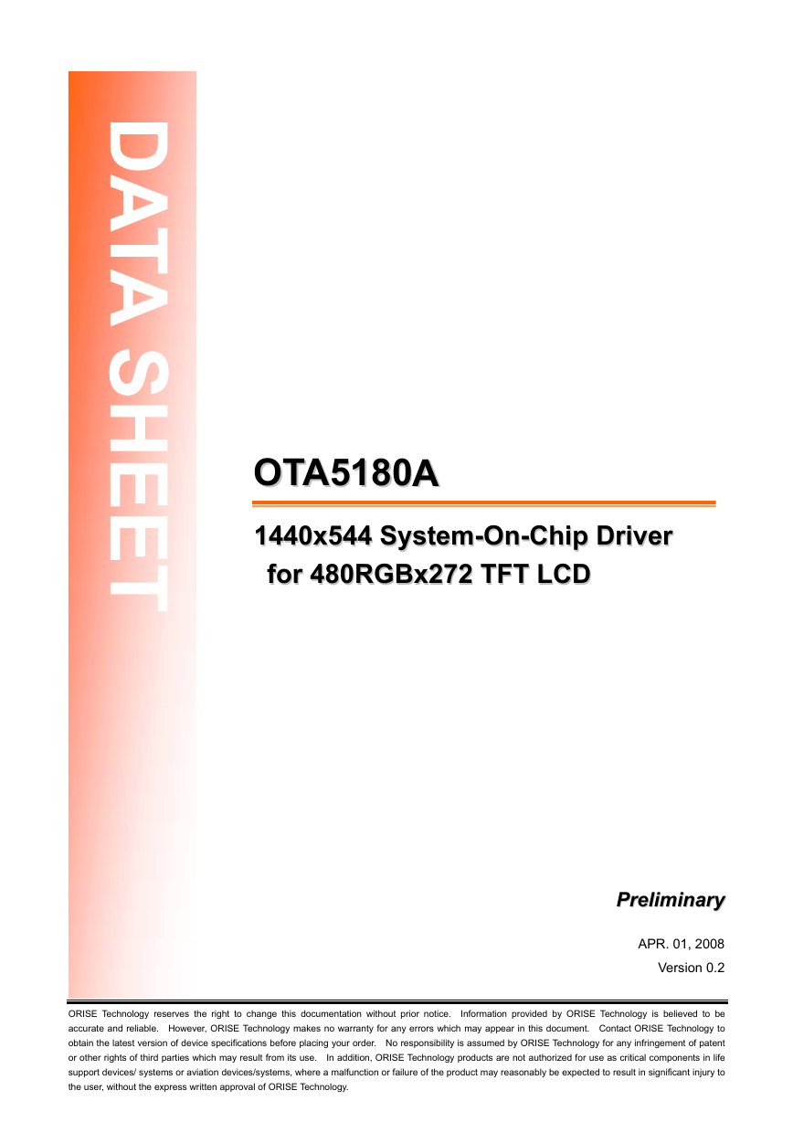
11444400xx554444 SSyysstteemm--OOnn--CChhiipp DDrriivveerr
ffoorr 448800RRGGBBxx227722 TTFFTT LLCCDD
PPrreelliimmiinnaarryy
APR. 01, 2008
Version 0.2
ORISE Technology reserves the right to change this documentation without prior notice. Information provided by ORISE Technology is believed to be
accurate and reliable. However, ORISE Technology makes no warranty for any errors which may appear in this document. Contact ORISE Technology to
obtain the latest version of device specifications before placing your order. No responsibility is assumed by ORISE Technology for any infringement of patent
or other rights of third parties which may result from its use. In addition, ORISE Technology products are not authorized for use as critical components in life
support devices/ systems or aviation devices/systems, where a malfunction or failure of the product may reasonably be expected to result in significant injury to
the user, without the express written approval of ORISE Technology.
�
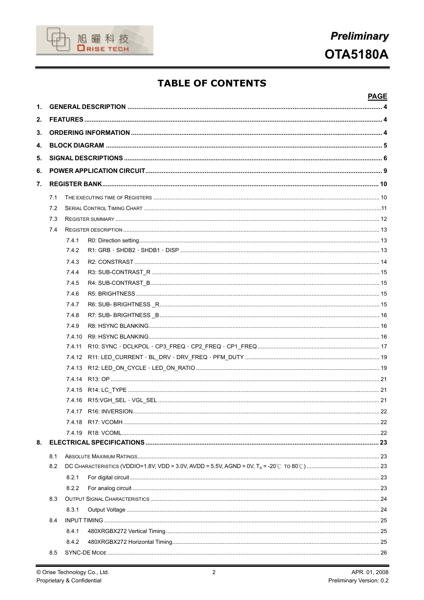
TABLE OF CONTENTS
PPrreelliimmiinnaarryy
OTA5180A
PAGE
1. GENERAL DESCRIPTION .............................................................................................................................................. 4
2. FEATURES ...................................................................................................................................................................... 4
3. ORDERING INFORMATION ............................................................................................................................................ 4
4. BLOCK DIAGRAM .......................................................................................................................................................... 5
5. SIGNAL DESCRIPTIONS ................................................................................................................................................ 6
6. POWER APPLICATION CIRCUIT.................................................................................................................................... 9
7. REGISTER BANK.......................................................................................................................................................... 10
7.1 THE EXECUTING TIME OF REGISTERS ............................................................................................................................................... 10
7.2 SERIAL CONTROL TIMING CHART ......................................................................................................................................................11
7.3 REGISTER SUMMARY ....................................................................................................................................................................... 12
7.4 REGISTER DESCRIPTION .................................................................................................................................................................. 13
7.4.1 R0: Direction setting........................................................................................................................................................ 13
7.4.2 R1: GRB、SHDB2、SHDB1、DISP .............................................................................................................................. 13
7.4.3 R2: CONSTRAST ........................................................................................................................................................... 14
7.4.4 R3: SUB-CONTRAST_R ................................................................................................................................................ 15
7.4.5 R4: SUB-CONTRAST_B................................................................................................................................................. 15
7.4.6 R5: BRIGHTNESS.......................................................................................................................................................... 15
7.4.7 R6: SUB- BRIGHTNESS _R........................................................................................................................................... 15
7.4.8 R7: SUB- BRIGHTNESS _B........................................................................................................................................... 16
7.4.9 R8: HSYNC BLANKING.................................................................................................................................................. 16
7.4.10 R9: HSYNC BLANKING.................................................................................................................................................. 16
7.4.11 R10: SYNC、DCLKPOL、CP3_FREQ、CP2_FREQ、CP1_FREQ ............................................................................. 17
7.4.12 R11: LED_CURRENT、BL_DRV、DRV_FREQ、PFM_DUTY ..................................................................................... 19
7.4.13 R12: LED_ON_CYCLE、LED_ON_RATIO .................................................................................................................... 19
7.4.14 R13: OP .......................................................................................................................................................................... 21
7.4.15 R14: LC_TYPE ............................................................................................................................................................... 21
7.4.16 R15:VGH_SEL、VGL_SEL ............................................................................................................................................ 21
7.4.17 R16: INVERSION............................................................................................................................................................ 22
7.4.18 R17: VCOMH.................................................................................................................................................................. 22
7.4.19 R18: VCOML................................................................................................................................................................... 22
8. ELECTRICAL SPECIFICATIONS.................................................................................................................................. 23
8.1 ABSOLUTE MAXIMUM RATINGS......................................................................................................................................................... 23
8.2 DC CHARACTERISTICS (VDDIO=1.8V, VDD = 3.0V, AVDD = 5.5V, AGND = 0V, TA = -20℃ TO 80℃) .............................................. 23
8.2.1 For digital circuit.............................................................................................................................................................. 23
8.2.2 For analog circuit ............................................................................................................................................................ 23
8.3 OUTPUT SIGNAL CHARACTERISTICS ................................................................................................................................................. 24
8.3.1 Output Voltage ................................................................................................................................................................ 24
INPUT TIMING .............................................................................................................................................................................. 25
480XRGBX272 Vertical Timing....................................................................................................................................... 25
8.4.1
8.4.2
480XRGBX272 Horizontal Timing................................................................................................................................... 25
8.5 SYNC-DE MODE ............................................................................................................................................................................ 26
8.4
© Orise Technology Co., Ltd.
Proprietary & Confidential
2
APR. 01, 2008
Preliminary Version: 0.2
�
PPrreelliimmiinnaarryy
OTA5180A
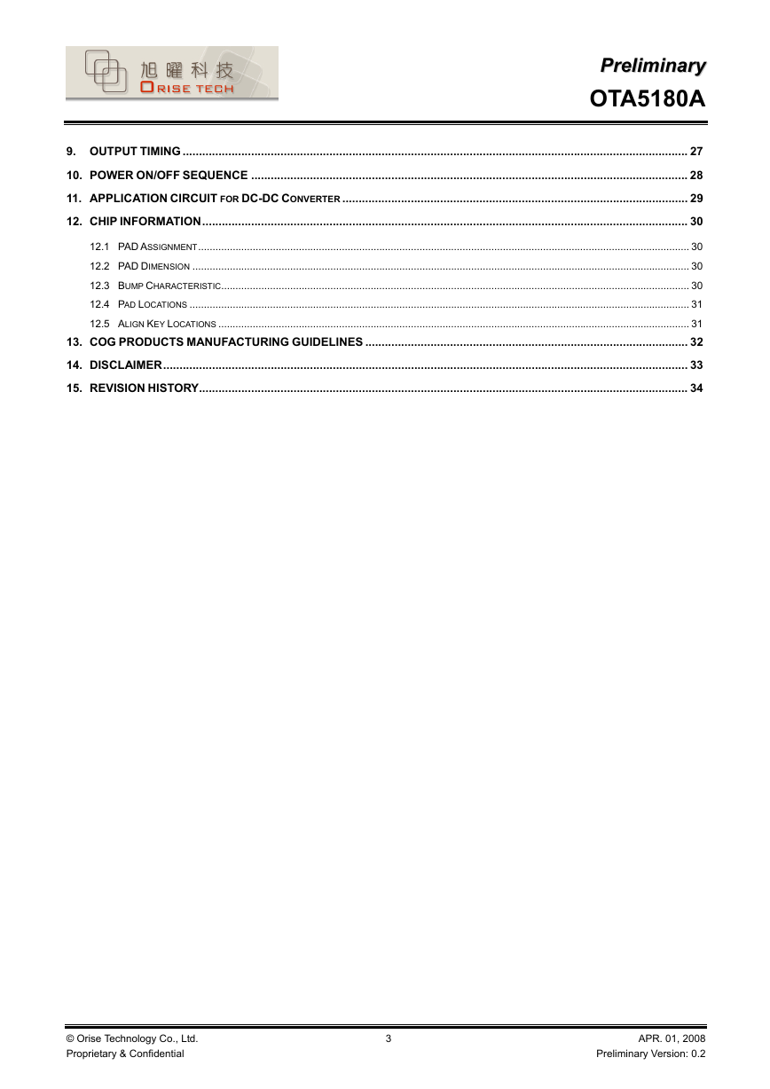
9. OUTPUT TIMING ........................................................................................................................................................... 27
10. POWER ON/OFF SEQUENCE ...................................................................................................................................... 28
11. APPLICATION CIRCUIT FOR DC-DC CONVERTER .......................................................................................................... 29
12. CHIP INFORMATION..................................................................................................................................................... 30
12.1 PAD ASSIGNMENT........................................................................................................................................................................... 30
12.2 PAD DIMENSION ............................................................................................................................................................................. 30
12.3 BUMP CHARACTERISTIC................................................................................................................................................................... 30
12.4 PAD LOCATIONS .............................................................................................................................................................................. 31
12.5 ALIGN KEY LOCATIONS .................................................................................................................................................................... 31
13. COG PRODUCTS MANUFACTURING GUIDELINES ................................................................................................... 32
14. DISCLAIMER................................................................................................................................................................. 33
15. REVISION HISTORY...................................................................................................................................................... 34
© Orise Technology Co., Ltd.
Proprietary & Confidential
3
APR. 01, 2008
Preliminary Version: 0.2
�
PPrreelliimmiinnaarryy
OTA5180A
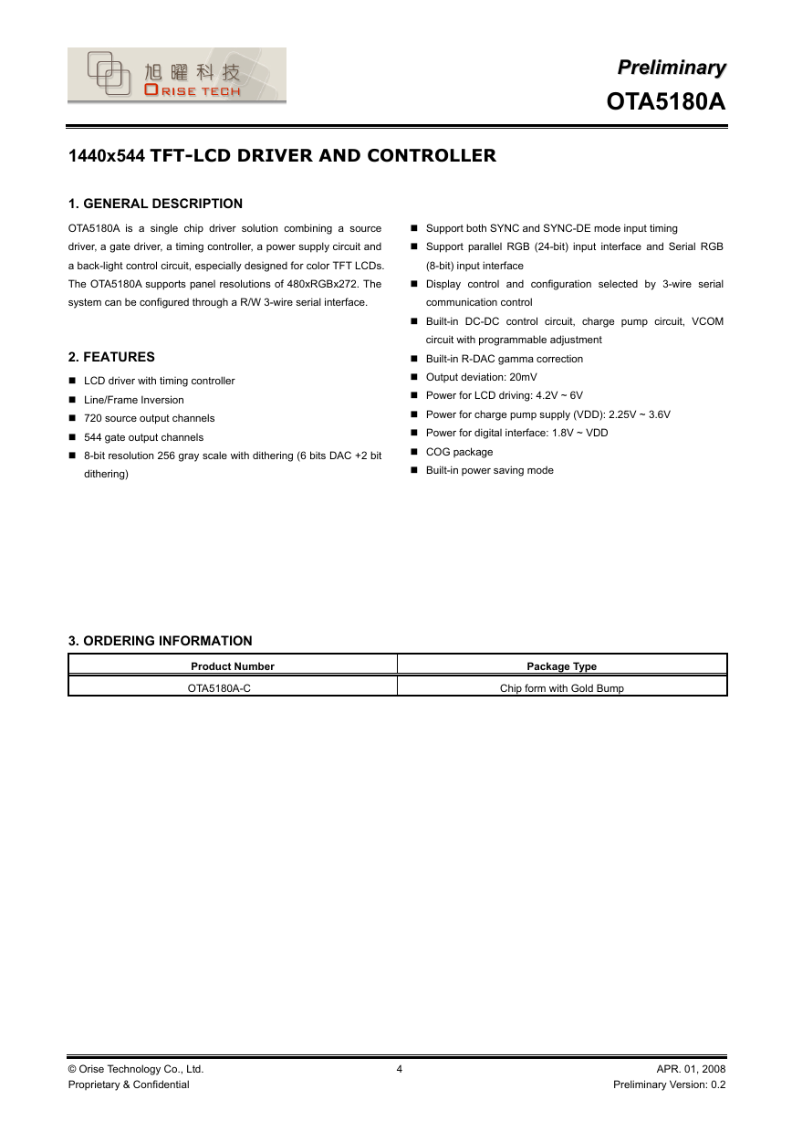
1440x544 TFT-LCD DRIVER AND CONTROLLER
1. GENERAL DESCRIPTION
OTA5180A is a single chip driver solution combining a source
driver, a gate driver, a timing controller, a power supply circuit and
a back-light control circuit, especially designed for color TFT LCDs.
The OTA5180A supports panel resolutions of 480xRGBx272. The
system can be configured through a R/W 3-wire serial interface.
2. FEATURES
LCD driver with timing controller
Line/Frame Inversion
720 source output channels
544 gate output channels
8-bit resolution 256 gray scale with dithering (6 bits DAC +2 bit
(8-bit) input interface
communication control
circuit with programmable adjustment
Built-in R-DAC gamma correction
Output deviation: 20mV
Power for LCD driving: 4.2V ~ 6V
Power for charge pump supply (VDD): 2.25V ~ 3.6V
Power for digital interface: 1.8V ~ VDD
COG package
Built-in power saving mode
Support both SYNC and SYNC-DE mode input timing
Support parallel RGB (24-bit) input interface and Serial RGB
Display control and configuration selected by 3-wire serial
Built-in DC-DC control circuit, charge pump circuit, VCOM
dithering)
3. ORDERING INFORMATION
Product Number
OTA5180A-C
Package Type
Chip form with Gold Bump
© Orise Technology Co., Ltd.
Proprietary & Confidential
4
APR. 01, 2008
Preliminary Version: 0.2
�
PPrreelliimmiinnaarryy
OTA5180A
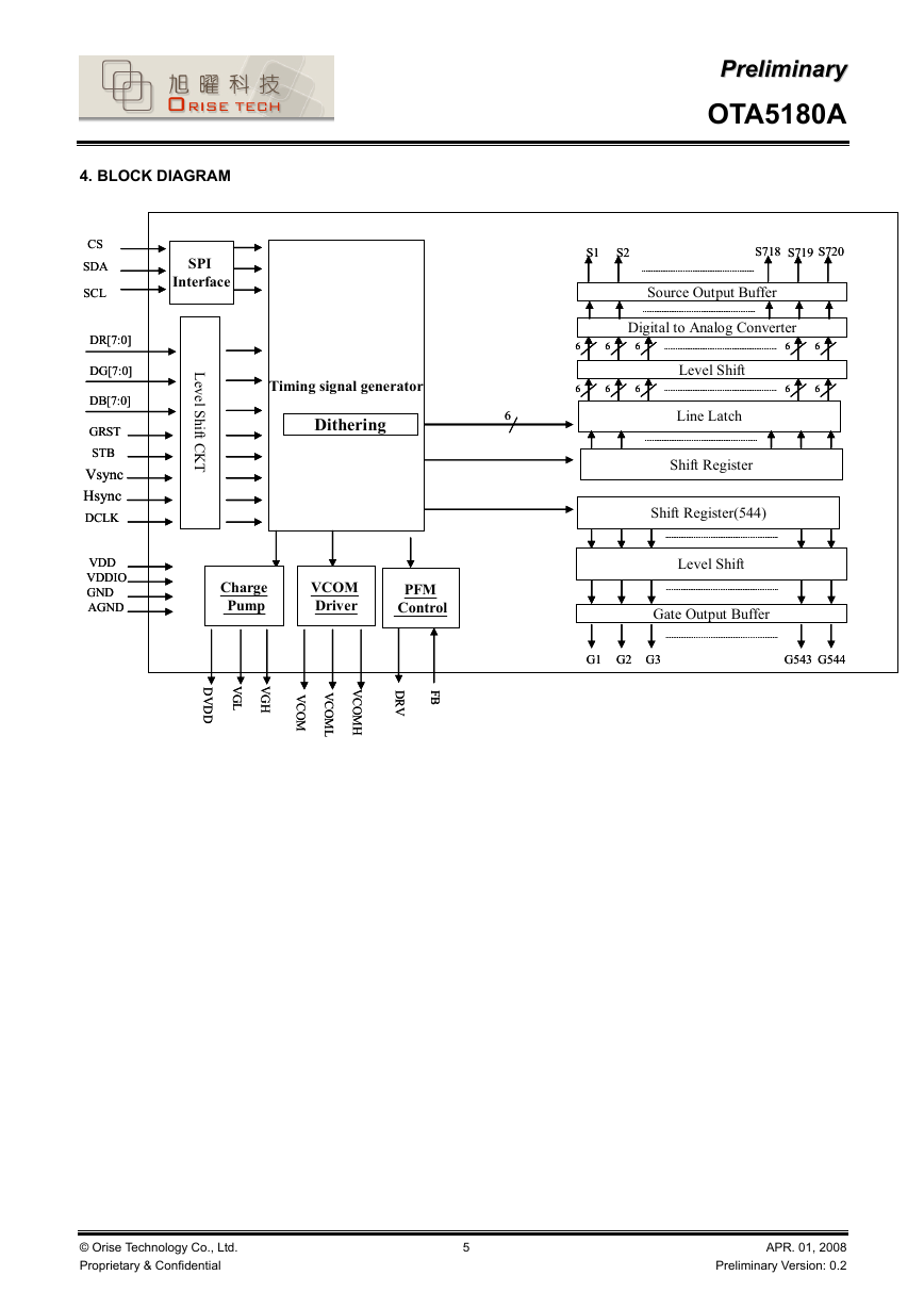
4. BLOCK DIAGRAM
CS
CS
SDA
SDA
SCL
SCL
DR[7:0]
DR[7:0]
DG[7:0]
DG[7:0]
DB[7:0]
DB[7:0]
GRST
GRST
STB
STB
Vsync
Vsync
Hsync
Hsync
DCLK
DCLK
VDD
VDD
VDDIO
VDDIO
GND
GND
AGND
AGND
SPI
SPI
Interface
Interface
L
L
e
e
v
v
e
e
l
l
S
S
h
h
i
i
f
f
t
t
C
C
K
K
T
T
Timing signal generator
Timing signal generator
Dithering
Dithering
6
6
Charge
Charge
Pump
Pump
VCOM
VCOM
Driver
Driver
PFM
PFM
Control
Control
V
V
G
G
L
L
V
V
G
G
H
H
D
D
V
V
D
D
D
D
V
V
C
C
O
O
M
M
V
V
C
C
O
O
M
M
L
L
V
V
C
C
O
O
M
M
H
H
D
D
R
R
V
V
F
F
B
B
S1
S1
S2
S2
S718 S719 S720
S718 S719 S720
Source Output Buffer
Source Output Buffer
Digital to Analog Converter
Digital to Analog Converter
6
6
6
6
6
6
Level Shift
Level Shift
6
6
6
6
6
6
6
6
6
6
6
6
6
6
6
6
6
6
6
6
6
6
6
6
Line Latch
Line Latch
Shift Register
Shift Register
Shift Register(544)
Shift Register(544)
Level Shift
Level Shift
Gate Output Buffer
Gate Output Buffer
G1 G2 G3
G1 G2 G3
G543 G544
G543 G544
© Orise Technology Co., Ltd.
Proprietary & Confidential
5
APR. 01, 2008
Preliminary Version: 0.2
�
5. SIGNAL DESCRIPTIONS
SYMBOL
TYPE
DESCRIPTION
PPrreelliimmiinnaarryy
OTA5180A
Serial Communication Interface / Timming Controller (Tcon) / Mode Selection
CS
SDA
SCL
I/O
(VDDIO) Serial communication chip select
(VDDIO) Serial communication data input and output
(VDDIO) Serial communication clock input
I
PARA_SERI
I
(VDDIO)
Parallel 24-bit and Serial 8-bit data input selection.
PARA_SERI=”H”, Parallel 24-bit RGB input through DR0~7, DB0~DB7,
DG0~DG7 (Default)
PARA_SERI=”L”, Serial 8-bit data input through DR0~DR7
When PARA_SERI=”H”, these will be treated as 8-bit digital Red data input
When PARA_SERI=”L”, these will be treated as serial 8-bit data input
I
I
I
I
(VDDIO)
I
(VDDIO)
DR0~DR7
DG0~DG7
DB0~DB7
DCLK
HSYNC
VSYNC
DE
SYNC
HDIR
VDIR
I
(VDDIO)
I
(VDDIO)
I
(VDDIO)
MVA_TN
TN_TYPE
I
I
I
(VDDIO)
(VDDIO) 8-bit digital Green data input, only valid when PARA_SERI=”H”
(VDDIO) 8-bit digital Blue data input, only valid when PARA_SERI=”H”
(VDDIO) Clock signal; latching data at the falling edge
(VDDIO) Horizontal sync signal; negative polarity
(VDDIO) Vertical sync signal; negative polarity
(VDDIO) Data input enable. Active High to enable the data input.
I
I
SYNC or SYNC-DE mode selection:
SYNC = “Low”: accepted SYNC-DE mode input timing (Default)
SYNC = “High”: accepted SYNC mode input timing
Horizontal scan direction control (Please refer to the register setting : HDIR)
HDIR(pin) = “Low” : The definition of HDIR register setting is inversion from
original.
HDIR(register) = “0” : Shift from left to right;
HDIR(register) = “1” : Shift from right to left. (Default of the Register)
HDIR(pin) = “High”:The definition of HDIR register setting is invariant.
(Default)
HDIR(register) = “0” : Shift from right to left;
HDIR(register) = “1” : Shift from left to right. (Default of the Register)
Vertical scan direction control (Please refer to the register setting : VDIR)
VDIR(pin) = “Low”: The definition of VDIR register setting is inversion from
original.
VDIR(register) = “0”: Shift from up to down;
VDIR(register) = “1”: Shift from down to up. (Default of the Register)
VDIR(pin) = “High”: The definition of VDIR register setting is invariant.
(Default)
VDIR(register) = “0”: Shift from down to up;
VDIR(register) = “1”: Shift from up to down. (Default of the Register)
Set the TN or MVA mode.
MVA_TN=“Low": TN
MVA_TN=“High": MVA mode. (Default)
To identify the liquid crystal is TN or not.
TN_TYPE =“Low": The liquid crystal is TN mode1, with lower VCOM power applied.
TN_TYPE =“High": The liquid crystal is TN mode2 or MVA, with higher VCOM power
applied. (Default)
© Orise Technology Co., Ltd.
Proprietary & Confidential
6
APR. 01, 2008
Preliminary Version: 0.2
�
PPrreelliimmiinnaarryy
OTA5180A
OP0
LOW
HIGH (Default)
LOW
HIGH
Driving capability
-25%
Normal (Default)
+25%
+50%
Charge pump power selection
When VDD=2.5V, PWR_SEL =“Low"
When VDD=3.3V, PWR_SEL =“High" (Default)
Source driver driving capability selection. OP0 and OP1 pins are internal
pulled to default setting.
OP1
LOW
LOW (Default)
HIGH
HIGH
Vsync polarity control.
VDPOL=”1”, negative polarity (default)
VDPOL=0, positive polarity
Hsync polarity control.
HDPOL=”1”, negative polarity (default)
HDPOL=”0”, positive polarity
DCLK polarity control.
DCLKPOL=”1”, negative polarity (default)
DCLKPOL=”0”, positive polarity
Data R[7:0] & B[7:0] exchanged internally
DATA_RB=”1” R[7:0]→B[7:0](internally) B[7:0]→R[7:0](internally)
DATA_RB=”0” R[7:0]→R[7:0](internally) B[7:0]→B[7:0](internally) (default)
Global reset. Active low, Internal pull high
Low voltage reset enable. Active high. Internal pull high.
Display control / standby mode selection.
DISP = “Low” : Standby; (Default)
DISP = “High” : Normal display
Source driver output signals
Gate driver output signals
Power transistor gate signal for the boost converter
Main boost regulator feedback input. Connect feedback resistive divider to GND. FB
threshold can be selected by register setting, usually 0.6V (default).
Frame polarity output for VCOM. Swing between VCOMH and VCOML.
Power supply for VCOM high level output.
Power supply for VCOM low level output.
Power supply for digital circuit
Ground pin for digital circuit
Power supply for charge pump circuit
Ground pin for charge pump circuit
Ground for analog circuit
Power supply for digital interface I/O pins
Power input pin for customer OTP.
7
APR. 01, 2008
Preliminary Version: 0.2
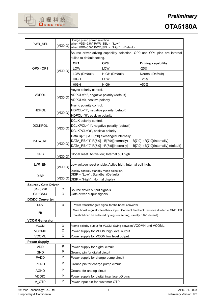
PWR_SEL
I
(VDDIO)
OP0 - OP1
I
(VDDIO)
VDPOL
HDPOL
DCLKPOL
DATA_RB
GRB
LVR_EN
DISP
I
(VDDIO)
I
(VDDIO)
I
(VDDIO)
I
(VDDIO)
I
(VDDIO)
I
(VDDIO)
I
(VDDIO)
Source / Gate Driver
S1~S720
G1~G544
DC/DC Converter
DRV
FB
VCOM Generator
VCOM
VCOMH
VCOML
Power Supply
VDD
GND
PVDD
PGND
AGND
VDDIO
V_OTP
O
O
O
I
O
C
C
P
P
P
P
P
P
P
© Orise Technology Co., Ltd.
Proprietary & Confidential
�
PPrreelliimmiinnaarryy
OTA5180A
Capacitor connect pin for internal charge pump. Refer to the illustration of
power application circuit.
Power setting capacitor connect pin
Power setting capacitor connect pins
Power setting capacitor connect pins
Power setting capacitor connect pins
Power setting capacitor connect pins. Positive power supply for gate driver
output.
Power setting capacitor connect pins. Negative power supply for gate driver
output.
Test pins for OriseTech internal testing only. User should leave it open.
Test pins for OriseTech internal testing only. Internal pull low. User should
leave it open or connect it to “low”.
Internal left pass line for COM signal between input and output pins
Internal right pass line for COM signal between input and output pins
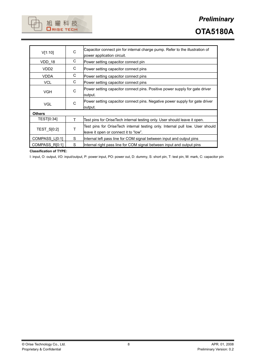
COMPASS_L[0:1]
COMPASS_R[0:1]
Classification of TYPE:
I: input, O: output, I/O: input/output, P: power input, PO: power out, D: dummy, S: short pin, T: test pin, M: mark, C: capacitor pin
V[1:10]
VDD_18
VDD2
VDDA
VCL
VGH
VGL
Others
TEST[0:34]
TEST_S[0:2]
C
C
C
C
C
C
C
T
T
S
S
8
APR. 01, 2008
Preliminary Version: 0.2
© Orise Technology Co., Ltd.
Proprietary & Confidential
�



 2023年江西萍乡中考道德与法治真题及答案.doc
 2012年重庆南川中考生物真题及答案.doc
 2013年江西师范大学地理学综合及文艺理论基础考研真题.doc
 2020年四川甘孜小升初语文真题及答案I卷.doc
 2020年注册岩土工程师专业基础考试真题及答案.doc
 2023-2024学年福建省厦门市九年级上学期数学月考试题及答案.doc
 2021-2022学年辽宁省沈阳市大东区九年级上学期语文期末试题及答案.doc
 2022-2023学年北京东城区初三第一学期物理期末试卷及答案.doc
 2018上半年江西教师资格初中地理学科知识与教学能力真题及答案.doc
 2012年河北国家公务员申论考试真题及答案-省级.doc
 2020-2021学年江苏省扬州市江都区邵樊片九年级上学期数学第一次质量检测试题及答案.doc
 2022下半年黑龙江教师资格证中学综合素质真题及答案.doc