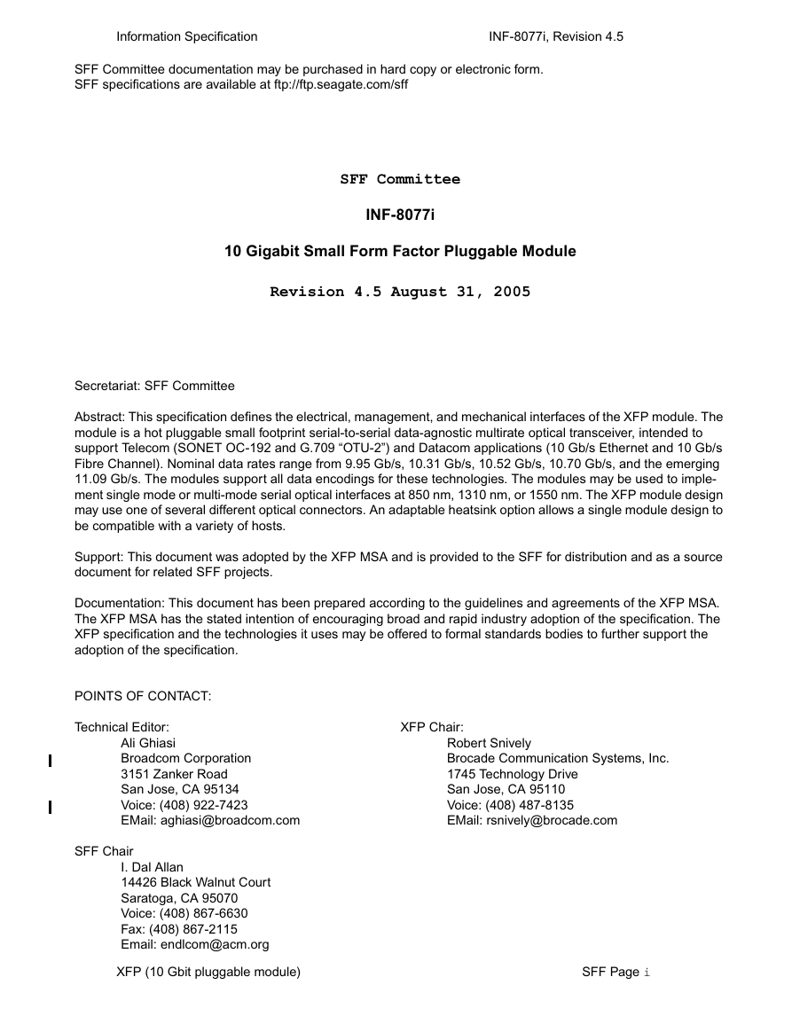
INF-8077i
10 Gigabit Small Form Factor Pluggable Module
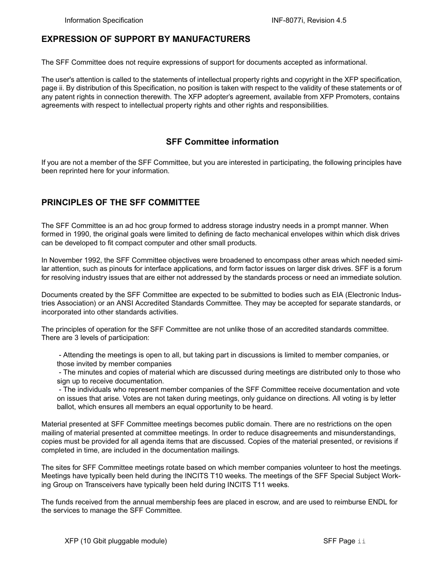
EXPRESSION OF SUPPORT BY MANUFACTURERS
SFF Committee information
PRINCIPLES OF THE SFF COMMITTEE
SFF Membership and Subscription application
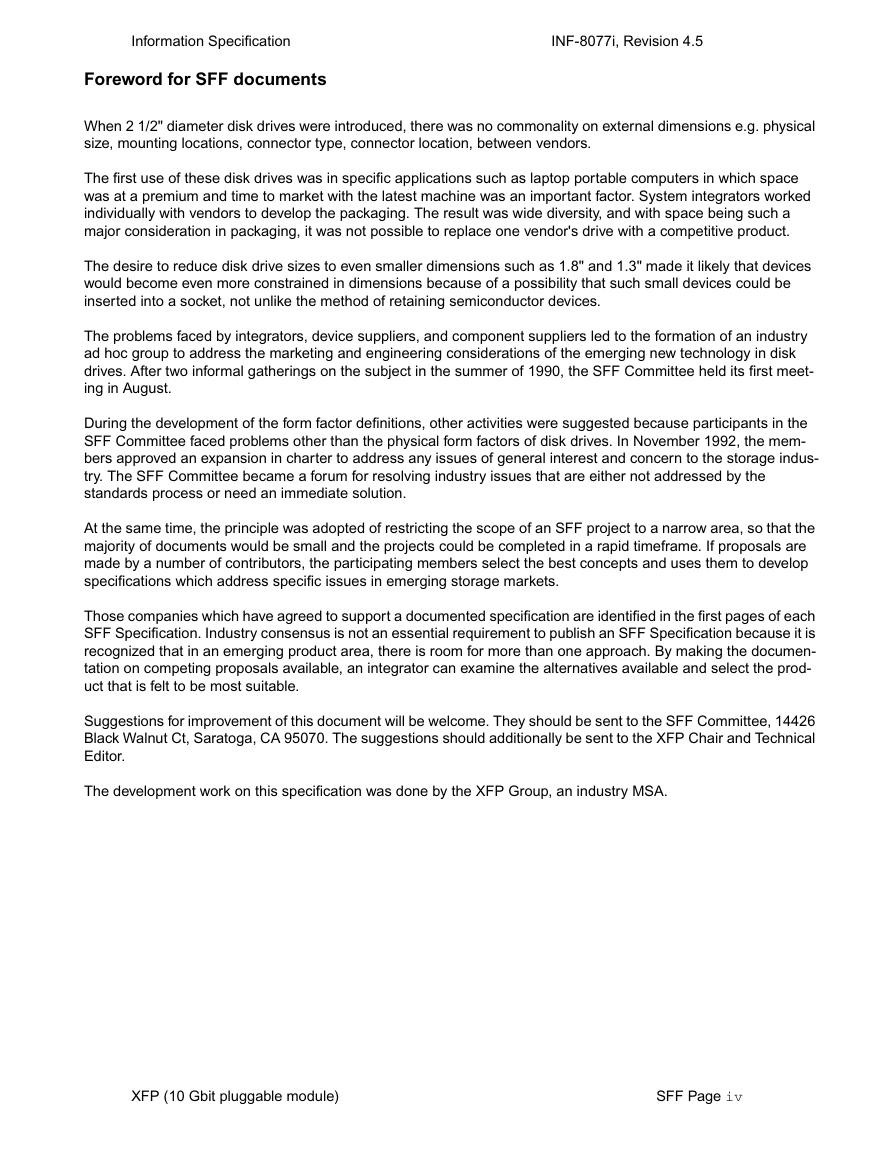
Foreword for SFF documents
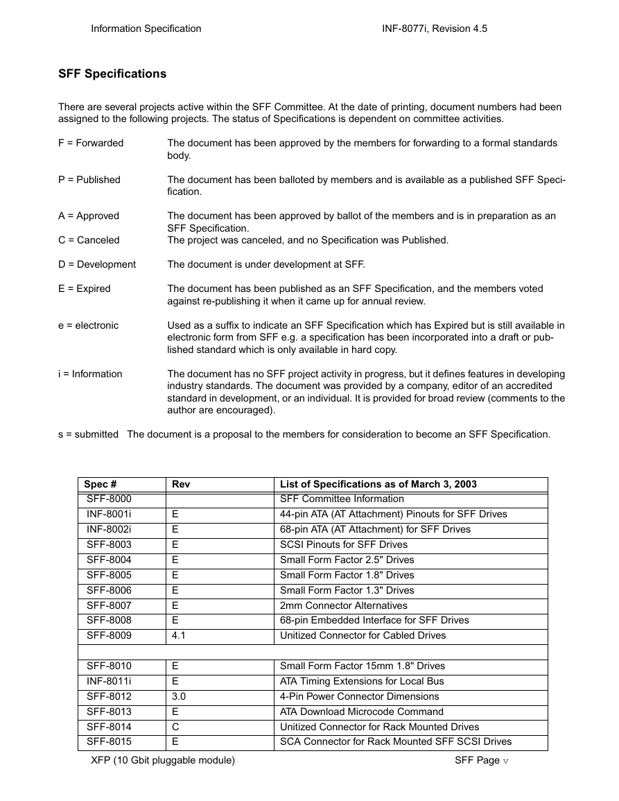
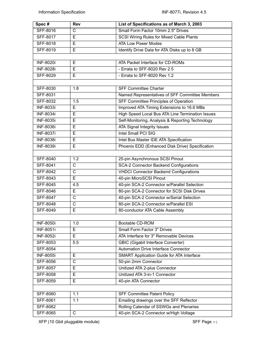
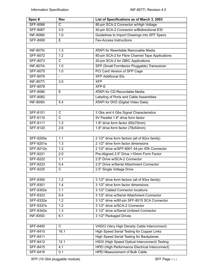
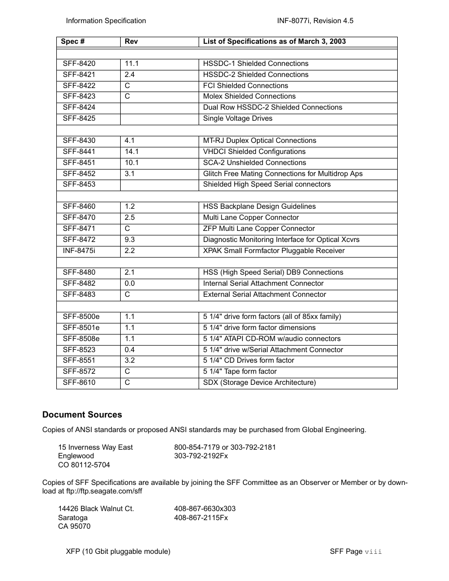
SFF Specifications
Document Sources
XFP Revision 4.5
XFP Legal Disclaimer
XFP Copyright Notice
XFP Identification of defects
XFP Publication History
XFP Foreword
XFP Contributors
XFP Acknowledgments
XFP Table of Contents
Chapter 1: Scope of XFP specification� 1
Chapter 2: XFP Electrical Interface� 3
Chapter 3: High Speed Electrical Specification XFI� 16
Chapter 4: XFP 2-Wire Interface Protocol� 42
Chapter 5: Management interface� 55
Chapter 6: Mechanical and Board definition� 98
XFP List of Tables
XFP List Figures
Chapter 1: Scope of XFP specification
1.1 Introduction
1.2 Requirements on Press announcements
Chapter 2: XFP Electrical Interface
2.1 Introduction
2.2 General Requirements
2.3 XFP Host Connector Definition
2.4 Low Speed Electrical Hardware Pins
2.4.1 Mod_NR
2.4.2 Mod_DeSel
2.4.3 Interrupt
2.4.4 TX_DIS
2.4.5 Mod_ABS
2.4.6 RX_LOS
2.4.7 P_Down/RST
2.4.7.1 Power Down Function
2.4.7.2 Reset Function
2.4.7.3 Module Behavior during Power Down and Reset
2.5 Low Speed Electrical Specifications
2.6 Timing Requirement of Control and Status I/O
2.7 XFP Power Requirement
2.7.1 Power Noise Output
2.7.2 Power Noise Susceptibility
2.7.3 Host Filtering
2.8 ESD
Chapter 3: High Speed Electrical Specification XFI
3.1 Introduction
3.2 XFI Applications Definition
3.3 XFI Termination and DC Blocking
3.4 XFI Jitter Definitions
3.5 XFI Compliance Channel
3.6 XFI ASIC/SerDes Specification
3.6.1 XFI ASIC/SerDes Transmitter Output Specifications at A (Informative)
3.6.2 XFI ASIC/SerDes Receiver Input Specifications at D (Informative)
3.7 XFI Host System Specification
3.7.1 XFI Host Transmitter Output Specifications at B
3.7.2 XFI Host Receiver Input Specifications at C
3.8 XFI Module Specifications
3.8.1 XFI Module Transmitter Input Specifications at B’
3.8.2 XFI Module Receiver Output Specifications at C’
3.9 Signal Conditioner
3.9.1 Telecom Module
3.9.2 Datacom Module
3.10 Reference Clock Specifications
3.10.1 Optional Synchronous CMU Clock
Chapter 4: XFP 2-Wire Interface Protocol
4.1 Introduction
4.2 XFP 2-Wire Timing Diagram
4.3 Memory Transaction Timing
4.4 Device Addressing and Operation
4.5 Read/Write Functionality
4.5.1 Packet Error Checking
4.5.2 XFP Memory Address Counter (Read and Write Operations)
4.5.3 Read Operations (Current Address Read)
4.5.4 Read Operations (Random Read)
4.5.5 Read Operations (Sequential Read)
4.5.6 Read Operation Packet Error Checking
4.5.7 Write Operations (Byte Write)
4.5.8 Write Operations (Sequential Write)
4.5.9 Write Operation Packet Error Checking
4.5.10 Write Operations (Acknowledge Polling)
Chapter 5: Management interface
5.0.1 Applicable Documents
5.1 Description of Lower Memory Map: Control Functions, Diagnostics, Table Access
5.2 Identifier
5.3 Signal Conditioner Control
5.4 2-Wire Serial Interface Checksum
5.5 Table Selection and Password Entry (Table 44)
5.6 Basic Monitoring Functions
5.7 Optional Variable Power Supply (VPS) Control
5.8 System BER Reporting
5.9 Wavelength Control
5.10 FEC Control
5.11 Interrupt System Logic
5.11.1 General Control and Status Bits
5.12 Timing for Soft Control and Status Functions
5.13 Description of Upper Memory Map Table 00h – Future Diagnostics Functions
5.14 Description of Upper Memory Map Table 01h – Serial ID Memory Map
5.15 Identifier
5.16 Extended Identifier
5.17 Connector
5.18 Interface Specification
5.19 Encoding
5.20 BR, Minimum
5.21 BR, maximum
5.22 Length (Standard single mode fiber)-km
5.23 Length (Extended Bandwidth 50 mm Multimode Fiber)
5.24 Length (50 um Multimode Fiber)
5.25 Length (62.5 um Multimode Fiber)
5.26 Length (Copper)
5.27 Device Technology
5.28 Vendor name
5.29 CDR Support
5.30 Vendor OUI
5.31 Vendor PN
5.32 Vendor Rev
5.33 Laser Wavelength
5.34 Laser Wavelength Tolerance
5.35 Maximum Case Temperature
5.36 CC_BASE
5.37 Power supply requirements
5.38 Vendor SN
5.39 Date Code
5.40 Diagnostic Monitoring Type
5.41 Enhanced Options
5.42 Auxiliary Monitoring
5.43 CC_EXT
5.44 Vendor Specific ID Field
5.45 Description of Upper Memory Map Table 02h – User EEPROM Data
5.46 Description of Upper Memory Map Tables 03h – 7Fh Vendor Specific Functions
5.47 Description of Upper Memory Map Tables 80h – FFh Reserved
Chapter 6: Mechanical and Board definition
6.1 Introduction
6.2 XFP Datums and Component Alignment
6.3 XFP Transceiver Package Dimensions
6.4 Mating of XFP Transceiver PCB to XFP Electrical Connector
6.5 Host Board Layout
6.6 Insertion, Extraction and Retention Forces for XFP Transceivers
6.7 Color Coding and Labeling of XFP Transceivers
6.8 Bezel and EMI Gasket Design for Systems Using XFP Transceivers
6.9 XFP Connector Mechanical Specifications
6.10 XFP Cage Assembly Dimensions
6.10.1 XFP Cage Housing
6.10.2 XFP Cage Rear EMI Gaskets
6.10.2.1 XFP Upper Rear EMI Gasket
6.10.2.2 Lower Rear EMI Gasket
6.10.2.3 XFP Intermediate Rear Cage EMI Gasket (Finger Stock)
6.10.3 XFP Cage Front Cage EMI Gasket (Finger Stock)
6.10.4 XFP Front Flange
6.11 XFP Heat Sink Clip Dimensions
6.12 An Example XFP Heat Sink
6.13 Environmental and Thermal
6.14 Dust/EMI Cover
Appendix A: Application Reference Model
A.1 ASIC/SerDes Compliance Testing
A.2 Host System Compliance Testing
A.3 XFP Module Compliance Testing
A.4 HOST SYSTEM COMPLIANCE TEST BOARD
A.4.1 Host System Compliance Board Material and Layer Stack-up
A.4.2 Host System Compliance Test Board Partlist
A.4.3 Schematic of Host System Compliance Test Board
A.4.4 Gerber file and S parameter measurements
A.5 XFP MODULE COMPLIANCE TEST BOARD
A.5.1 XFP Module Board Material and Layer Stack-up
A.5.2 XFP Module Compliance Board Partlist
A.5.3 Schematic of the XFP Compliance Test Board
A.5.4 Gerber files and Measured S-Parameters
Appendix B: XFI Channel Measurements and Modeling
B.1 System Overview
B.2 Design Guideline
B.3 Using System Simulation for Channel Modeling
Appendix C: Differential S-Parameters and TDR
C.1 Choosing S-Parameters vs TDR
C.2 Differential Impedance
C.3 4 Port Single-Ended S-Parameter Definition
C.4 2 Port Mixed Mode Differential S-Parameter Definition
Appendix D: Optimum Via Design
D.1 Vias
D.2 Single-ended Vias
D.3 Differential Vias
D.4 GSSG Differential Vias
Appendix E: Jitter Methodology and Measurement
E.1 Eye Mask Compliance
E.2 Non-EQJ Jitter Eye Mask
E.3 Stress Eye Test for RX Tolerance Testing
E.3.1 Introduction
E.3.2 Test equipment
E.3.3 Types of jitter
E.3.4 Calibration
E.3.5 Testing
E.4 Jitter Peaking Specifications and Measurements
E.5 AC Common Mode Test
E.6 Termination Mismatch
E.7 Power supply noise testing methodology
E.7.1 Power Supply Noise compliance
E.7.2 Power Supply Noise Methodology
E.7.3 Power Supply Noise Methodology
Appendix F: XFI Implementation for BER 1E-15
F.1 XFI Electrical Implementation for BER 1E-15
F.1.1 XFI ASIC/SerDes Transmitter Output Jitter Specifications at A for BER 1E-15
F.1.2 XFI ASIC/SerDes Receiver Input Jitter Specifications at D for BER 1E-15
F.1.3 XFI Host Transmitter Output Jitter Specifications at B for BER 1E-15
F.1.4 XFI Host Receiver Input Jitter Specifications at C for BER 1E-15
F.1.5 FI Module Transmitter Input Jitter Specifications at B’ for BER 1E-15
F.1.6 XFI Module Receiver Output Jitter Specifications at C’ for BER 1E-15
Appendix G: Module Thermal Testing
G.1 Module Thermal Power Classes
G.2 Thermal Test Recommendation
G.3 Thermal Test Configuration



 2023年江西萍乡中考道德与法治真题及答案.doc
 2012年重庆南川中考生物真题及答案.doc
 2013年江西师范大学地理学综合及文艺理论基础考研真题.doc
 2020年四川甘孜小升初语文真题及答案I卷.doc
 2020年注册岩土工程师专业基础考试真题及答案.doc
 2023-2024学年福建省厦门市九年级上学期数学月考试题及答案.doc
 2021-2022学年辽宁省沈阳市大东区九年级上学期语文期末试题及答案.doc
 2022-2023学年北京东城区初三第一学期物理期末试卷及答案.doc
 2018上半年江西教师资格初中地理学科知识与教学能力真题及答案.doc
 2012年河北国家公务员申论考试真题及答案-省级.doc
 2020-2021学年江苏省扬州市江都区邵樊片九年级上学期数学第一次质量检测试题及答案.doc
 2022下半年黑龙江教师资格证中学综合素质真题及答案.doc