Flexible static memory controller (FSMC)
RM0008
Table 123. FSMC_BCRx bit fields
Bit No.
Bit name
Value to set
31-16
15
14
13-10
9
8
7
6
5-4
3-2
1
0
0x0000
ASYNCWAIT
Set to 1 if the memory supports this feature. Otherwise keep at 0.
EXTMOD
WAITPOL
BURSTEN
FACCEN
MWID
MTYP
MUXEN
MBKEN
0x0
0x0
Meaningful only if bit 15 is 1
0x0
-
0x1
As needed
0x2 (NOR)
0x1
0x1
Table 124. FSMC_BTRx bit fields
Bit No.
Bit name
Value to set
31-20
0x0000
19-16
BUSTURN
15-8
DATAST
Duration of the last phase of the access (BUSTURN+1 HCLK)
Duration of the second access phase (DATAST+3 HCLK cycles for
read accesses and DATAST+1 HCLK cycles for write accesses).
This value cannot be 0 (minimum is 1)
7-4
3-0
ADDHLD
Duration of the middle phase of the access (ADDHLD+1 HCLK
cycles).This value cannot be 0 (minimum is 1).
ADDSET
Duration of the first access phase (ADDSET+1 HCLK cycles).
WAIT management in asynchronous accesses
If the asynchronous memory asserts a WAIT signal to advise that it's not yet ready to accept
or to provide data, the ASYNCWAIT bit has to be set in FSMC_BCRx register.
If the WAIT signal is active (high or low depending on the WAITPOL bit), the second access
phase (Data setup phase) programmed by the DATAST bits, is extended until WAIT
becomes inactive. Unlike the data setup phase, the first access phases (Address setup and
Address hold phases), programmed by the ADDSET and ADDHLD bits, are not WAIT
sensitive and so they are not prolonged.
The data phase must be programmed so that WAIT can be detected 4 HCLK cycles before
the data sampling. The following cases must be considered:
510/1096
Doc ID 13902 Rev 14
�
RM0008
Flexible static memory controller (FSMC)
1. Memory asserts the WAIT signal aligned to NOE/NWE which toggles:
data_setup phase >= 4 * HCLK + max_wait_assertion_time
2. Memory asserts the WAIT signal aligned to NEx (or NOE/NWE not toggling):
if max_wait_assertion_time > (address_phase + hold_phase)
data_setup phase >= 4 * HCLK + (max_wait_assertion_time - address_phase -
hold_phase)
otherwise
data_setup phase >= 4 * HCLK
Where max_wait_assertion_time is the maximum time taken by the memory to assert the
WAIT signal once NEx/NOE/NWE is low.
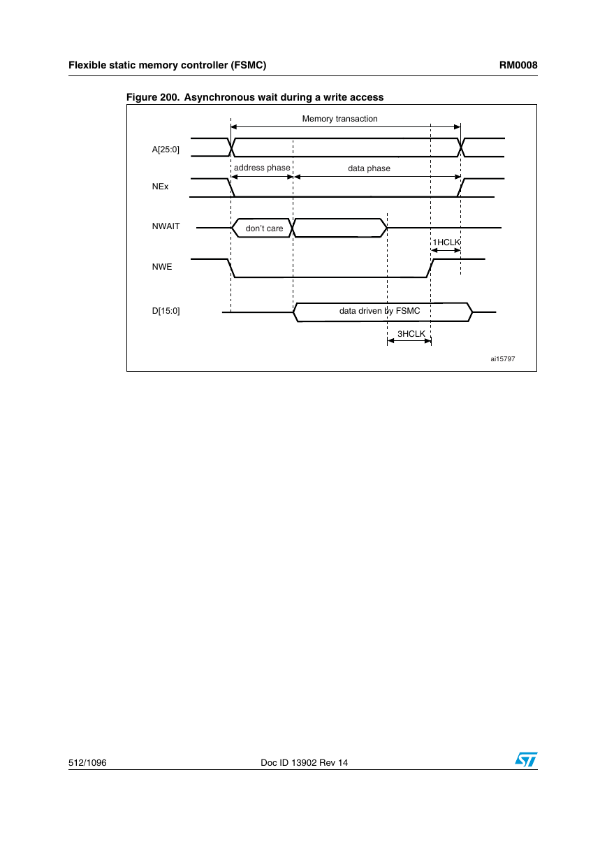
The Figure 199 and Figure 200 show the number of HCLK clock cycles that memory
access is extended after WAIT is removed by the asynchronous memory (independently of
the above cases).
Figure 199. Asynchronous wait during a read access
Memory transaction
A[25:0]
NOE
D[15:0]
Doc ID 13902 Rev 14
511/1096
�
Flexible static memory controller (FSMC)
RM0008
Figure 200. Asynchronous wait during a write access
Memory transaction
A[25:0]
NEx
NWAIT
NWE
D[15:0]
address phase
data phase
don’t care
1HCLK
data driven by FSMC
3HCLK
ai15797
512/1096
Doc ID 13902 Rev 14
�


 2023年江西萍乡中考道德与法治真题及答案.doc
 2012年重庆南川中考生物真题及答案.doc
 2013年江西师范大学地理学综合及文艺理论基础考研真题.doc
 2020年四川甘孜小升初语文真题及答案I卷.doc
 2020年注册岩土工程师专业基础考试真题及答案.doc
 2023-2024学年福建省厦门市九年级上学期数学月考试题及答案.doc
 2021-2022学年辽宁省沈阳市大东区九年级上学期语文期末试题及答案.doc
 2022-2023学年北京东城区初三第一学期物理期末试卷及答案.doc
 2018上半年江西教师资格初中地理学科知识与教学能力真题及答案.doc
 2012年河北国家公务员申论考试真题及答案-省级.doc
 2020-2021学年江苏省扬州市江都区邵樊片九年级上学期数学第一次质量检测试题及答案.doc
 2022下半年黑龙江教师资格证中学综合素质真题及答案.doc