Intensity-directed Equalizer for Chirp Compensation Enabling
DML-based 56Gb/s PAM4 C-band Delivery over 35.9km SSMF
Kuo Zhang(1),(2), Qunbi Zhuge(2),(3),*, Haiyun Xin(1), Mohamed Morsy-Osman(2), Eslam El-Fiky(2),
Lilin Yi(1), Weisheng Hu(1), David V. Plant(2)
(1) State Key Laboratory of Advanced Optical Communication System and Networks, Department of
Electronic Engineering, Shanghai Jiao Tong University, Shanghai, 200240, China
(2) Dept. of ECE, McGill University, Montreal, QC H3A 2A7, Canada, *qunbi.zhuge@mcgill.ca
(3) Ciena Corporation, Ottawa, Ontario, K2H 8E9, Canada
Abstract We propose an intensity-directed equalizer to address chirp induced eye skewing and inter-
symbol interference in DML-DD systems, and experimentally demonstrate a transmission of 56Gb/s
PAM4 signals using a 16.8GHz C-band DML over 35.9 km SSMF.
low-cost optical
laser
(DML) can be used
Introduction
The emerging bandwidth-hungry datacenter and
client side applications require high data-rate
transceivers. Directly
and
modulated
to
implement low-cost transmitters, and it has other
advantages such as high output power and
small footprint. The main distinction of direct
modulation from external modulation such as
Mach-Zahnder modulators or electro-absorption
lasers is that electrical signal is directly applied
to the laser’s gain section. The dependence of
refractive index on carrier density makes the
directly modulated signal suffer from severe
distortions due to the interaction between laser
chirp and fiber chromatic dispersion (CD). This
limits
in C-band
transmission, which has advantages such as
DWDM compatibility and lower attenuation, and
thus most of previous high speed DML-based
systems are at O-band1. It is reported that, for
C-band DML-based direct detection (DML-DD)
transmission without optical CD compensation
or other optical processing, the record distance
for a 56Gb/s PAM4 signal is 20km2.
the application of DMLs
In this paper, regarding DMLs’ intrinsic chirp
property, we propose and experimentally
demonstrate an intensity-directed feedforward
and decision feedback equalizer (ID-FFE/ID-
DFE) to not only remove the inter-symbol
interference (ISI) caused by bandwidth limitation
as conventional FFE/DFE does3, but also
compensate the chirp-induced eye skewing and
ISI. This equalizer applies different coefficients
to interfering symbols according to their intensity
levels and has comparable computational
complexity as conventional FFE/DFE. With this
equalizer and a 16.8GHz DML, we demonstrate
56Gb/s PAM4 C-band transmission over 35.9km
standard single mode fiber (SSMF) without
optical CD compensation or other optical
processing, which is a record distance to the
best of our knowledge.
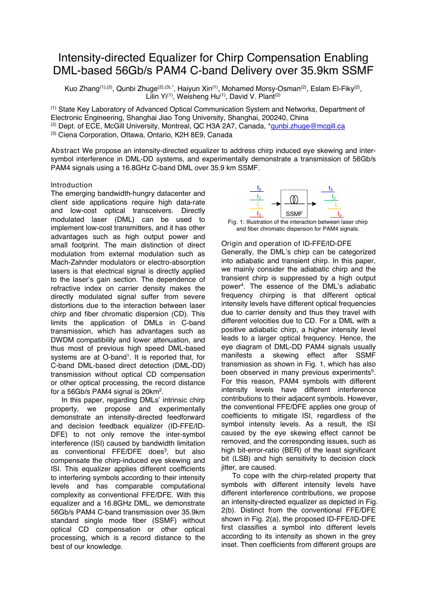
Fig. 1: Illustration of the interaction between laser chirp
and fiber chromatic dispersion for PAM4 signals.
is
Origin and operation of ID-FFE/ID-DFE
Generally, the DML’s chirp can be categorized
into adiabatic and transient chirp. In this paper,
we mainly consider the adiabatic chirp and the
transient chirp is suppressed by a high output
power4. The essence of the DML’s adiabatic
frequency chirping
that different optical
intensity levels have different optical frequencies
due to carrier density and thus they travel with
different velocities due to CD. For a DML with a
positive adiabatic chirp, a higher intensity level
leads to a larger optical frequency. Hence, the
eye diagram of DML-DD PAM4 signals usually
manifests a skewing effect after SSMF
transmission as shown in Fig. 1, which has also
been observed in many previous experiments5.
For this reason, PAM4 symbols with different
intensity
interference
contributions to their adjacent symbols. However,
the conventional FFE/DFE applies one group of
coefficients to mitigate ISI, regardless of the
symbol intensity levels. As a result, the ISI
caused by the eye skewing effect cannot be
removed, and the corresponding issues, such as
high bit-error-ratio (BER) of the least significant
bit (LSB) and high sensitivity to decision clock
jitter, are caused.
levels have different
To cope with the chirp-related property that
symbols with different intensity levels have
different interference contributions, we propose
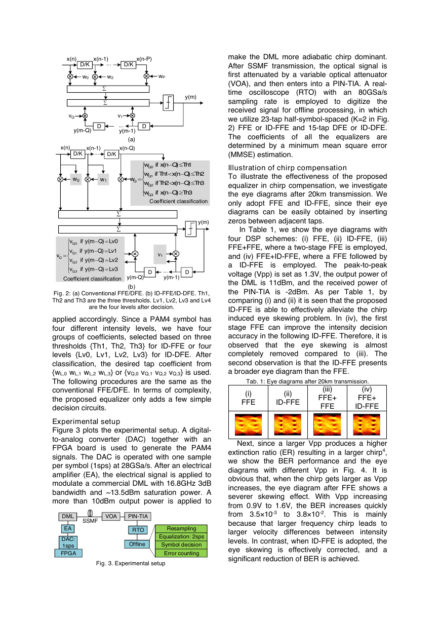
an intensity-directed equalizer as depicted in Fig.
2(b). Distinct from the conventional FFE/DFE
shown in Fig. 2(a), the proposed ID-FFE/ID-DFE
first classifies a symbol into different levels
according to its intensity as shown in the grey
inset. Then coefficients from different groups are
f3f2f1f0f3f2f1f0SSMF�
make the DML more adiabatic chirp dominant.
After SSMF transmission, the optical signal is
first attenuated by a variable optical attenuator
(VOA), and then enters into a PIN-TIA. A real-
time oscilloscope (RTO) with an 80GSa/s
sampling rate
the
received signal for offline processing, in which
we utilize 23-tap half-symbol-spaced (K=2 in Fig.
2) FFE or ID-FFE and 15-tap DFE or ID-DFE.
The coefficients of all
the equalizers are
determined by a minimum mean square error
(MMSE) estimation.
is employed
to digitize
Illustration of chirp compensation
To illustrate the effectiveness of the proposed
equalizer in chirp compensation, we investigate
the eye diagrams after 20km transmission. We
only adopt FFE and ID-FFE, since their eye
diagrams can be easily obtained by inserting
zeros between adjacent taps.
ID-FFE
In Table 1, we show the eye diagrams with
four DSP schemes: (i) FFE, (ii) ID-FFE, (iii)
FFE+FFE, where a two-stage FFE is employed,
and (iv) FFE+ID-FFE, where a FFE followed by
a
is employed. The peak-to-peak
voltage (Vpp) is set as 1.3V, the output power of
the DML is 11dBm, and the received power of
the PIN-TIA is -2dBm. As per Table 1, by
comparing (i) and (ii) it is seen that the proposed
ID-FFE is able to effectively alleviate the chirp
induced eye skewing problem. In (iv), the first
stage FFE can improve the intensity decision
accuracy in the following ID-FFE. Therefore, it is
is almost
observed
completely removed compared
to (iii). The
second observation is that the ID-FFE presents
a broader eye diagram than the FFE.
the eye skewing
that
Tab. 1: Eye diagrams after 20km transmission.
(iv)
(iii)
(i)
(ii)
FFE
ID-FFE
FFE+
FFE
FFE+
ID-FFE
Next, since a larger Vpp produces a higher
extinction ratio (ER) resulting in a larger chirp4,
we show the BER performance and the eye
diagrams with different Vpp in Fig. 4. It is
obvious that, when the chirp gets larger as Vpp
increases, the eye diagram after FFE shows a
severer skewing effect. With Vpp increasing
from 0.9V to 1.6V, the BER increases quickly
from 3.5×10⁻³
is mainly
because that larger frequency chirp leads to
larger velocity differences between intensity
levels. In contrast, when ID-FFE is adopted, the
eye skewing is effectively corrected, and a
significant reduction of BER is achieved.
to 3.8×10⁻². This
(a)
(b)
Fig. 2: (a) Conventional FFE/DFE. (b) ID-FFE/ID-DFE. Th1,
Th2 and Th3 are the three thresholds. Lv1, Lv2, Lv3 and Lv4
are the four levels after decision.
applied accordingly. Since a PAM4 symbol has
four different intensity levels, we have four
groups of coefficients, selected based on three
thresholds {Th1, Th2, Th3} for ID-FFE or four
levels {Lv0, Lv1, Lv2, Lv3} for ID-DFE. After
classification, the desired tap coefficient from
{wL,0 wL,1 wL,2 wL,3} or {vQ,0 vQ,1 vQ,2 vQ,3} is used.
The following procedures are the same as the
conventional FFE/DFE. In terms of complexity,
the proposed equalizer only adds a few simple
decision circuits.
Experimental setup
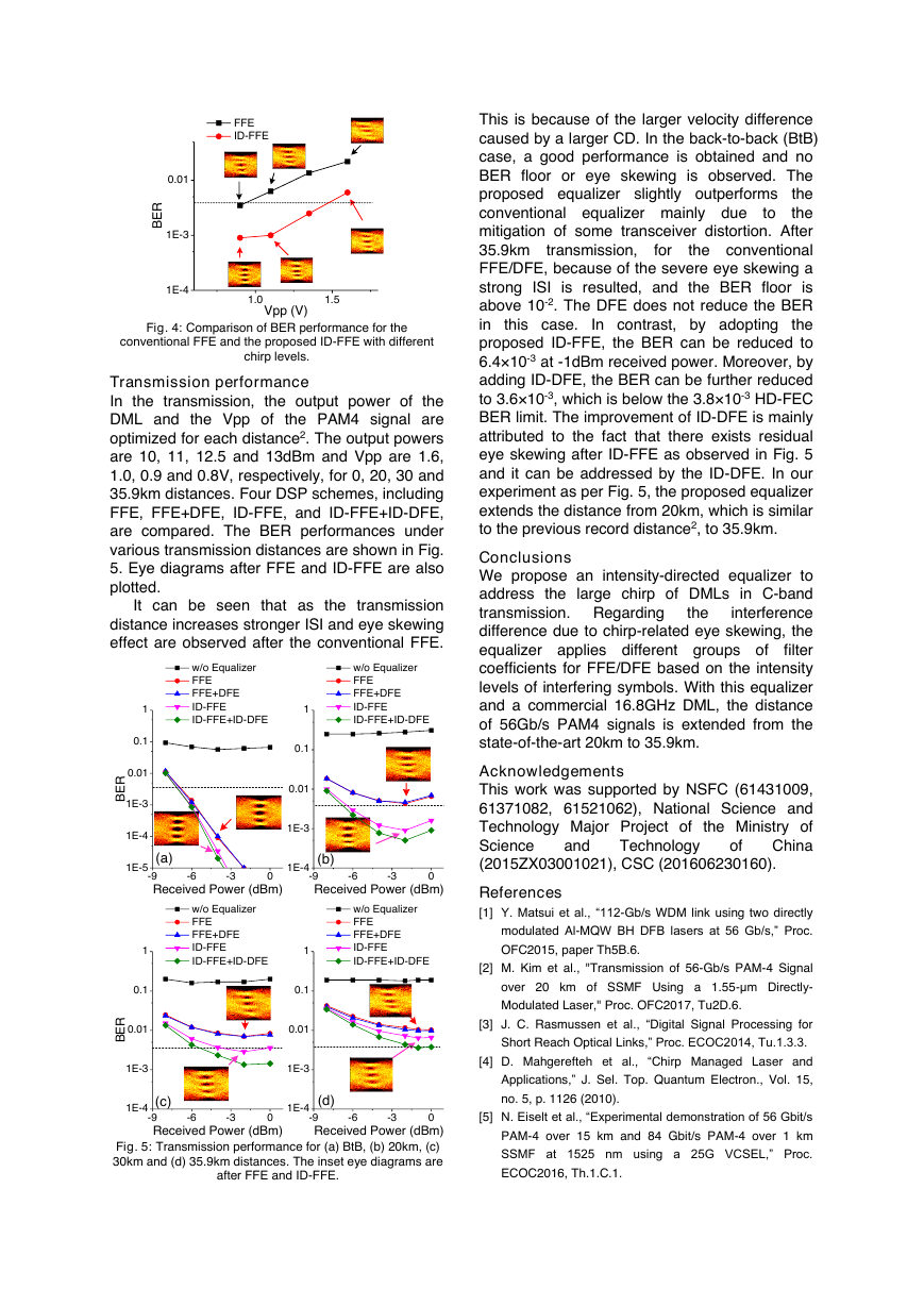
Figure 3 plots the experimental setup. A digital-
to-analog converter (DAC) together with an
FPGA board is used to generate the PAM4
signals. The DAC is operated with one sample
per symbol (1sps) at 28GSa/s. After an electrical
amplifier (EA), the electrical signal is applied to
modulate a commercial DML with 16.8GHz 3dB
bandwidth and ~13.5dBm saturation power. A
more than 10dBm output power is applied to
Fig. 3. Experimental setup
Time (s)Amplitude (AU)In-phase Signal00.0050.010.0150.020.025-505Time (s)Amplitude (AU)In-phase Signal00.0050.010.0150.020.025-505Time (s)Amplitude (AU)In-phase Signal00.0050.010.0150.020.025-505Time (s)Amplitude (AU)In-phase Signal00.0050.010.0150.020.025-505DMLDAC: 1spsFPGAVOAPIN-TIARTOOfflineSSMFEAResamplingEqualization: 2spsSymbol decisionError countingD/Kw0w2wP...x(n)x(n-1)x(n-P)DD...v1vQD/Ky(m-1)y(m-Q)y(m)Coefficient classificationD/KD/K...x(n)Coefficient classificationx(n-1)x(n-Q)DD...v1,0,1,2,3()0()1()2()3QQQQQvifymQLvvifymQLvvvifymQLvvifymQLvy(m)y(m-1)y(m-Q),0,1,2,3()11()22()3()3QQQQQwifxnQThwifThxnQThwwifThxnQThwifxnQThw1w0�
Fig. 4: Comparison of BER performance for the
conventional FFE and the proposed ID-FFE with different
chirp levels.
Transmission performance
In the transmission, the output power of the
DML and the Vpp of the PAM4 signal are
optimized for each distance2. The output powers
are 10, 11, 12.5 and 13dBm and Vpp are 1.6,
1.0, 0.9 and 0.8V, respectively, for 0, 20, 30 and
35.9km distances. Four DSP schemes, including
FFE, FFE+DFE, ID-FFE, and ID-FFE+ID-DFE,
are compared. The BER performances under
various transmission distances are shown in Fig.
5. Eye diagrams after FFE and ID-FFE are also
plotted.
It can be seen that as the transmission
distance increases stronger ISI and eye skewing
effect are observed after the conventional FFE.
for
transmission,
This is because of the larger velocity difference
caused by a larger CD. In the back-to-back (BtB)
case, a good performance is obtained and no
BER floor or eye skewing is observed. The
proposed equalizer slightly outperforms
the
conventional equalizer mainly due
the
to
mitigation of some transceiver distortion. After
35.9km
the conventional
FFE/DFE, because of the severe eye skewing a
strong ISI is resulted, and the BER floor is
above 10-2. The DFE does not reduce the BER
in this case. In contrast, by adopting the
proposed ID-FFE, the BER can be reduced to
6.4×10⁻³ at -1dBm received power. Moreover, by
adding ID-DFE, the BER can be further reduced
to 3.6×10⁻³, which is below the 3.8×10⁻³ HD-FEC
BER limit. The improvement of ID-DFE is mainly
attributed to the fact that there exists residual
eye skewing after ID-FFE as observed in Fig. 5
and it can be addressed by the ID-DFE. In our
experiment as per Fig. 5, the proposed equalizer
extends the distance from 20km, which is similar
to the previous record distance2, to 35.9km.
the
Conclusions
We propose an intensity-directed equalizer to
address the large chirp of DMLs in C-band
transmission. Regarding
interference
difference due to chirp-related eye skewing, the
equalizer applies different groups of
filter
coefficients for FFE/DFE based on the intensity
levels of interfering symbols. With this equalizer
and a commercial 16.8GHz DML, the distance
of 56Gb/s PAM4 signals is extended from the
state-of-the-art 20km to 35.9km.
Acknowledgements
This work was supported by NSFC (61431009,
61371082, 61521062), National Science and
Technology Major Project of the Ministry of
Science
China
(2015ZX03001021), CSC (201606230160).
Technology
and
of
References
[1] Y. Matsui et al., “112-Gb/s WDM link using two directly
modulated Al-MQW BH DFB lasers at 56 Gb/s,” Proc.
OFC2015, paper Th5B.6.
[2] M. Kim et al., "Transmission of 56-Gb/s PAM-4 Signal
over 20 km of SSMF Using a 1.55-μm Directly-
Modulated Laser," Proc. OFC2017, Tu2D.6.
[3] J. C. Rasmussen et al., “Digital Signal Processing for
Short Reach Optical Links,” Proc. ECOC2014, Tu.1.3.3.
[4] D. Mahgerefteh et al., “Chirp Managed Laser and
Applications,” J. Sel. Top. Quantum Electron., Vol. 15,
no. 5, p. 1126 (2010).
[5] N. Eiselt et al., “Experimental demonstration of 56 Gbit/s
PAM-4 over 15 km and 84 Gbit/s PAM-4 over 1 km
SSMF at 1525 nm using a 25G VCSEL,” Proc.
Fig. 5: Transmission performance for (a) BtB, (b) 20km, (c)
30km and (d) 35.9km distances. The inset eye diagrams are
after FFE and ID-FFE.
ECOC2016, Th.1.C.1.
Time (s)Amplitude (AU)In-phase Signal024681012x 10-3-505Time (s)Amplitude (AU)In-phase Signal024681012x 10-3-505Time (s)Amplitude (AU)In-phase Signal024681012x 10-3-505Time (s)Amplitude (AU)In-phase Signal024681012x 10-3-505Time (s)Amplitude (AU)In-phase Signal024681012x 10-3-505Time (s)Amplitude (AU)In-phase Signal024681012x 10-3-5051.01.51E-41E-30.01BERVpp (V) FFE ID-FFETime (s)Amplitude (AU)In-phase Signal024681012x 10-3-505Time (s)Amplitude (AU)In-phase Signal024681012x 10-3-505Time (s)Amplitude (AU)In-phase Signal024681012x 10-3-505Time (s)Amplitude (AU)In-phase Signal024681012x 10-3-505(a)(d)Time (s)Amplitude (AU)In-phase Signal024681012x 10-3-505Time (s)Amplitude (AU)In-phase Signal024681012x 10-3-505-9-6-301E-51E-41E-30.010.11BERReceived Power (dBm) w/o Equalizer FFE FFE+DFE ID-FFE ID-FFE+ID-DFE-9-6-301E-41E-30.010.11BERReceived Power (dBm) w/o Equalizer FFE FFE+DFE ID-FFE ID-FFE+ID-DFETime (s)Amplitude (AU)In-phase Signal024681012x 10-3-505Time (s)Amplitude (AU)In-phase Signal024681012x 10-3-505(b)-9-6-301E-41E-30.010.11BERReceived Power (dBm) w/o Equalizer FFE FFE+DFE ID-FFE ID-FFE+ID-DFE(c)-9-6-301E-41E-30.010.11BERReceived Power (dBm) w/o Equalizer FFE FFE+DFE ID-FFE ID-FFE+ID-DFE�


 2023年江西萍乡中考道德与法治真题及答案.doc
 2012年重庆南川中考生物真题及答案.doc
 2013年江西师范大学地理学综合及文艺理论基础考研真题.doc
 2020年四川甘孜小升初语文真题及答案I卷.doc
 2020年注册岩土工程师专业基础考试真题及答案.doc
 2023-2024学年福建省厦门市九年级上学期数学月考试题及答案.doc
 2021-2022学年辽宁省沈阳市大东区九年级上学期语文期末试题及答案.doc
 2022-2023学年北京东城区初三第一学期物理期末试卷及答案.doc
 2018上半年江西教师资格初中地理学科知识与教学能力真题及答案.doc
 2012年河北国家公务员申论考试真题及答案-省级.doc
 2020-2021学年江苏省扬州市江都区邵樊片九年级上学期数学第一次质量检测试题及答案.doc
 2022下半年黑龙江教师资格证中学综合素质真题及答案.doc