logo资料库

Mimaki打印机-CF2-0912说明书.pdf

第1页 / 共186页
第2页 / 共186页
第3页 / 共186页
第4页 / 共186页
第5页 / 共186页
第6页 / 共186页
第7页 / 共186页
第8页 / 共186页
资料共186页,剩余部分请下载后查看
TABLE OF CONTENTS
Foreward
About model name
For safe operation
For safe operation
Precautions in installation
How to read this operation manual
Structure of this operation manual
Features of the device
Chapter 1 SET-UP
Installation site
Effective cutting area
Checking the accessories
Configuration and Function
Main unit
Head
Operation panel
Connecting the Cables
Connecting the signal wire cable for the blower
Connecting the interface cable
Connecting the power cable
Turning the power on/off
Turning the power on
Turning the power off
Emergency stop
How to stop the device in an emergency
How to reset the emergency stop
LOCAL/REMOTE Modes
LOCAL mode and the indication on the LCD
REMOTE mode and the indications on the LCD
Matching the functions of the device to the specifications of the computer
Setting communication conditions [INTERFACE]
Rendering the set values on the personal computer effective [MODE SET] > [CMD SW]
Setting the response value with respect to the valid area [MODE SET] > [OH UNIT]
Setting the command origin [MODE SET] > [ORIGIN]
Setting the resolution (GDP) [MODE SET] > [GDP]
Matching the specifications on the plotter's side
Setting for automatic head retract [AUTO VIEW]
Auto-OFF feature of the vacuum
Auto-OFF/Panel-OFF[MODE SET]>[VACUUM]
CHAPTER 2 BASIC OPERATION
Basic operation on the LOCAL menu
LOCAL menu
MODE SET menu
Basic operation on the LOCAL menu
Basic operation flow chart
Moving the head
Moving the head by "VIEW" function
Fixing a work
Fixing a work that is comparatively light in weight
Fixing heavy-weight packing etc.
Adjusting the blade and the pen
Cutter holders 4N and 10N (for unit C)
Cutter holder 2N (for unit B)
Reciprocal cutter holder (for unit B)
Swivel cutter
Attaching the tools
Attaching the pen and the swivel blade
Attaching the tangential cutter
Attaching the reciprocal cutter (cutter holder)
Installing the crease roller
Adjusting the height of the head
Attaching the work holder
Selecting a tool [TOOL SELECT]
Setting cutting conditions [CONDITION]
Setting items
Set values
Checking cutting conditions [TEST CUT]
Checking the status of tools
Setting the cutting area [CUT AREA]
Setting the origin (Origin for Plotting)
Interruption of Processing (Plotting, Cutting or Creasing)
Interruption of processing [DATA CLEAR]
CHAPTER 3 WHEN ABNORMAL CONDITIONS ARE ENCOUNTERED
If any of the below-stated phenomena takes place
Cutting depth is insufficient [CONDITION] > [PRESS CORRECT]
The work remains uncut at the cutting start and end [CONDITION] > [START/END CORRECT]
[TOOL ADJUST] > [CIRCLE q-ADJUST]
Corrugated board is cut out at flutes though creasing is performed [CONDITION] > [PRESS (Y)]
Tools are not aligned to each other [TOOL SELECT]
Flowchart of checking and adjusting procedures
General explanation of the adjustment of tools
Adjustment of the cutter
Adjustment of the roller
How to adjust the tools
If there is a sign of failure
The device not at all actuates even when the power to the device is turned on
The device fails to actuate even when data is transmitted from CAD
Error arises when transmitting data
The tool drags on the sheet of paper
Dotted lines or blurred lines are plotted
There is no reciprocal vibration
Troubles for which error messages are given on the LCD
Errors that can be corrected by users
Errors that cannot be corrected by users
CHAPTER 4 APPLICATION FUNCTIONS
Assignment of pen numbers [MODE SET] > [PEN ASIGN]
Setting the number cut function [MODE SET] > [MULTI-PASS]
Setting the ONE-stroke cutting [MODE SET] > [ONE STROKE]
Setting the direction of rotation for the coordinate axis [MODE SET] > [ROTATE]
Setting the cutter stroke [MODE SET] > [Z STROKE]
Setting the unit to be used for indication [MODE SET] > [UNIT]
Setting the DUMMY CUT operation of the SWIVEL BLADE [MODE SET] > [DUMMY CUT]
Alignment of mechanical axes to ruled lines printed [AXIS ALIGN]
Expand the cutting area [EXPANDS]
CHAPTER 5 REGISTER MARK DETECT FUNCTION
Setting of register mark detect
How to display the register mark setting on LCD
Precautions in preparing data with register mark
Size of the square mark
Size of the register mark
The area where register marks and designs can be arranged
No-plotting area around the register marks
The size of, and the distance between, register marks
Color of Register mark
Register mark Blurred
Setting of register mark detect operation
Precautions on register mark detection
How to display the register mark setting on LCD
Settings for detect
Continuous cut with Register mark
Initialize the register mark scale adjustment [SC.CLR]
CHAPTER 6 Self-test
Confirmation of cutting quality only by the single unit of the device [SELF TEST]
Cutting quality * / Sample *** / Circle cutting R = ***
Dump test [SELF TEST]
Executing the data dump
Execution of the parameter dump
APPENDIX
A. Replacing the blade tips
Tangential cutter blade
Swivel blade
B. Local menu structure
RC-head model
RT-head model
R-head model
C. Output samples
Cutting quality 1
Cutting quality 2
ASCII dump list
Sample (coated)
Sample (E corrugated)
Sample (B corrugated)
Circle cutting R = 3/5/10/20/50/100
Parameter dump list
D. Specifications
Basic specifications
Specifications for interface specifications
E. Maintenance
Cutting panel surface
Unit B
Cover
F. OPTIONAL ACCESSORIES
Swivel cutter components
Reciprocal Relationships
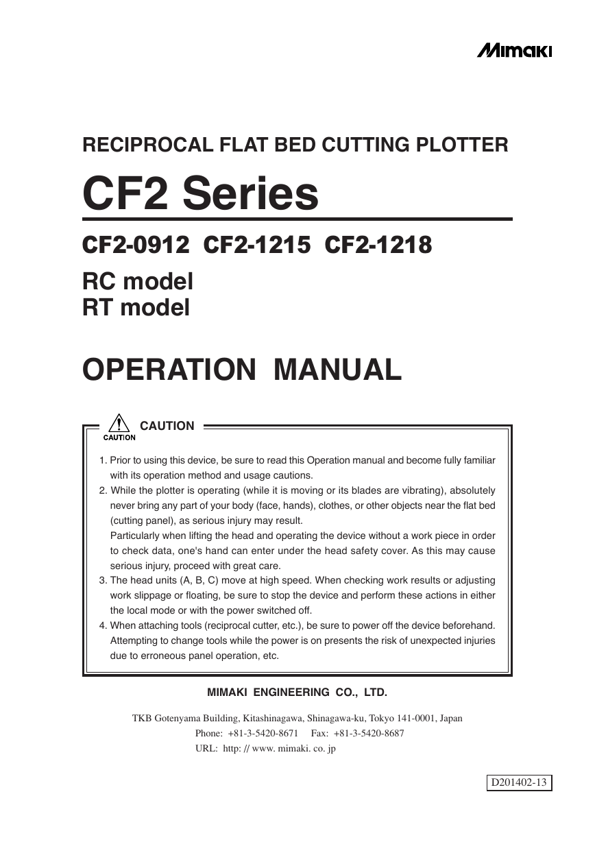
RECIPROCAL FLAT BED CUTTING PLOTTER CF2 Series CF2-0912 CF2-1215 CF2-1218 RC model RT model OPERATION MANUAL CAUTION 1. Prior to using this device, be sure to read this Operation manual and become fully familiar with its operation method and usage cautions. 2. While the plotter is operating (while it is moving or its blades are vibrating), absolutely never bring any part of your body (face, hands), clothes, or other objects near the flat bed (cutting panel), as serious injury may result. Particularly when lifting the head and operating the device without a work piece in order to check data, one's hand can enter under the head safety cover. As this may cause serious injury, proceed with great care. 3. The head units (A, B, C) move at high speed. When checking work results or adjusting work slippage or floating, be sure to stop the device and perform these actions in either the local mode or with the power switched off. 4. When attaching tools (reciprocal cutter, etc.), be sure to power off the device beforehand. Attempting to change tools while the power is on presents the risk of unexpected injuries due to erroneous panel operation, etc. MIMAKI ENGINEERING CO., LTD. TKB Gotenyama Building, Kitashinagawa, Shinagawa-ku, Tokyo 141-0001, Japan Phone: +81-3-5420-8671 Fax: +81-3-5420-8687 URL: http: // www. mimaki. co. jp D201402-13
This device is a first-class information processing device (information processing device that shall be commissioned in a commercial and industrial area) and conforms to the Voluntary Control Council Interference (VCCI) standard that has been developed for the purpose of prevention of radio disturbance in commercial or industrial areas. This device, therefore, can interfere with radios and televisions if put into service in a residential area and its adjacent areas. Correct handling procedure shall be followed according to this Operation manual. In the case where MIMAKI-designated cable is not used for the connection of this device, limits provided by VCCI rules can be exceeded. To prevent this, use of MIMAKI-designated cable is essential for the connection of this device. Interference to televisions and radios The product covered by this Operation manual produces high frequency waves while it is in opera- tion. The product can interfere with radios and televisions if set up or commissioned under improper conditions. The product is not guaranteed against any damage to specific-purpose radio and televisions. The product’s interference with your radio or television will be checked by turning off the power to the product. If the interference is elimiated by turning the product off, the product is the cause of interference. In the event that the product is the cause of interference, try to elimiate it by taking one of th following corrective measures or taking some of them in combination. • Change the direction of the antenna of your radio/television to find one that avoids interference. • Install your radio/television at a place that is sufficiently spaced from the product. • Connect the plug of your radio/television into a receptacle that does not share the power supply with the product. DISCLAIMER OF WARRANTY DISCLAIMER OF WARRANTY: THIS LIMITED WARRANTY OF MIMAKI SHALL BE THE SOLE AND EXCLUSIVE WARRANTY AND IS IN LIEU OF ALL OTHER WARRANTIES, EXPRESS OR IMPLIED, INCLUDING, BUT NOT LIMITED TO, ANY IMPLIED WARRANTY OF MERCHANTABILITY OR FITNESS, AND MIMAKI NEITHER ASSUMES NOR AUTHORIZES DEALER TO ASSUME FOR IT ANY OTHER OBLIGATION OR LIABILITY OR MAKE ANY OTHER WARRANTY OR MAKE ANY OTHER WARRANTY IN CONNECTION WITH ANY PRODUCT WITH- OUT MIMAKIÅfS PRIOR WRITTEN CONSENT. IN NO EVENT SHALL MIMAKI BE LIABLE FOR SPECIAL, INCIDENTAL OR CONSEQUENTIAL DAMAGES OR FOR LOSS OF PROFITS OF DEALER OR CUSTOMERS OF ANY PRODUCT. • Reproduction of this manual in whole or in part is strictly prohibited.
FOREWARD Congratulations on your purchase of a “CF2 Series” of reciprocal flat bed cutting plotter. This Operation manual is intended for RC model and RT model under the “CF2 Series.” Any function for which no head name is designated is common to all models. Please read and fully understand this Operation manual before putting the machine into service. It is also necessary to keep this Operation manual on hand. • This device uses blades and is extremely dangerous while it is operating. Abso- lutely never bring your hands or head near the head as doing so may result in cut fingers, etc. NOTES • Make arrangements to deliver this Operation manual to the person in charge of the operation of this device. • This Operation manual has been carefully prepared for your easy understanding, however, please do not hesitate to contact a distributor or our office in your country if you have any questions. • Description contained in this Operation manual are subject to change without notice. • In the case where this Operation manual should be illegible due to destruction by fire or break- age, purchase another copy of the Operation manual from our office. — i —
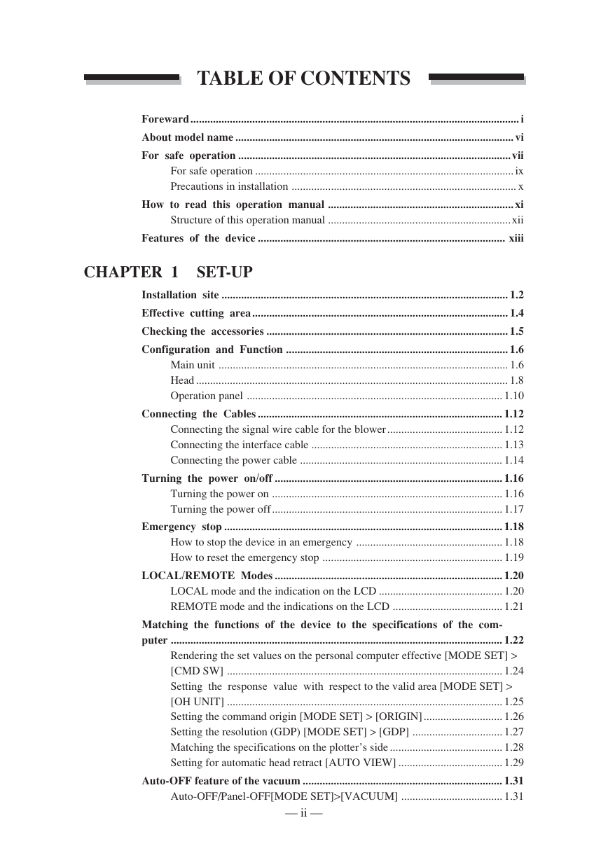
TABLE OF CONTENTS Foreward..................................................................................................................... i About model name ................................................................................................... vi For safe operation .................................................................................................vii For safe operation ............................................................................................ ix Precautions in installation ................................................................................ x How to read this operation manual .................................................................. xi Structure of this operation manual .................................................................xii Features of the device ........................................................................................ xiii CHAPTER 1 SET-UP Installation site ...................................................................................................... 1.2 Effective cutting area........................................................................................... 1.4 Checking the accessories ...................................................................................... 1.5 Configuration and Function ............................................................................... 1.6 Main unit ....................................................................................................... 1.6 Head ............................................................................................................... 1.8 Operation panel ........................................................................................... 1.10 Connecting the Cables ....................................................................................... 1.12 Connecting the signal wire cable for the blower ......................................... 1.12 Connecting the interface cable .................................................................... 1.13 Connecting the power cable ........................................................................ 1.14 Turning the power on/off ................................................................................. 1.16 Turning the power on .................................................................................. 1.16 Turning the power off.................................................................................. 1.17 Emergency stop ................................................................................................... 1.18 How to stop the device in an emergency .................................................... 1.18 How to reset the emergency stop ................................................................ 1.19 LOCAL/REMOTE Modes ................................................................................. 1.20 LOCAL mode and the indication on the LCD ............................................ 1.20 REMOTE mode and the indications on the LCD ....................................... 1.21 Matching the functions of the device to the specifications of the com- puter ...................................................................................................................... 1.22 Rendering the set values on the personal computer effective [MODE SET] > [CMD SW] .................................................................................................. 1.24 Setting the response value with respect to the valid area [MODE SET] > [OH UNIT] .................................................................................................. 1.25 Setting the command origin [MODE SET] > [ORIGIN] ............................ 1.26 Setting the resolution (GDP) [MODE SET] > [GDP] ................................ 1.27 Matching the specifications on the plotter’s side ........................................ 1.28 Setting for automatic head retract [AUTO VIEW] ..................................... 1.29 Auto-OFF feature of the vacuum ....................................................................... 1.31 Auto-OFF/Panel-OFF[MODE SET]>[VACUUM] .................................... 1.31 — ii —
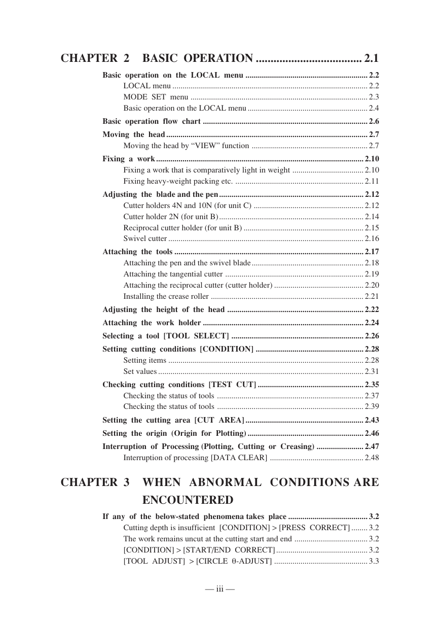
CHAPTER 2 BASIC OPERATION .................................... 2.1 Basic operation on the LOCAL menu ............................................................ 2.2 LOCAL menu ................................................................................................ 2.2 MODE SET menu ....................................................................................... 2.3 Basic operation on the LOCAL menu ........................................................... 2.4 Basic operation flow chart ................................................................................. 2.6 Moving the head ................................................................................................... 2.7 Moving the head by “VIEW” function ......................................................... 2.7 Fixing a work...................................................................................................... 2.10 Fixing a work that is comparatively light in weight ................................... 2.10 Fixing heavy-weight packing etc. ............................................................... 2.11 Adjusting the blade and the pen....................................................................... 2.12 Cutter holders 4N and 10N (for unit C) ...................................................... 2.12 Cutter holder 2N (for unit B)....................................................................... 2.14 Reciprocal cutter holder (for unit B) ........................................................... 2.15 Swivel cutter ................................................................................................ 2.16 Attaching the tools ............................................................................................. 2.17 Attaching the pen and the swivel blade....................................................... 2.18 Attaching the tangential cutter .................................................................... 2.19 Attaching the reciprocal cutter (cutter holder) ............................................ 2.20 Installing the crease roller ........................................................................... 2.21 Adjusting the height of the head ................................................................... 2.22 Attaching the work holder ............................................................................... 2.24 Selecting a tool [TOOL SELECT] ................................................................. 2.26 Setting cutting conditions [CONDITION] ..................................................... 2.28 Setting items ................................................................................................ 2.28 Set values ..................................................................................................... 2.31 Checking cutting conditions [TEST CUT] .................................................... 2.35 Checking the status of tools ........................................................................ 2.37 Checking the status of tools ........................................................................ 2.39 Setting the cutting area [CUT AREA] .......................................................... 2.43 Setting the origin (Origin for Plotting) ......................................................... 2.46 Interruption of Processing (Plotting, Cutting or Creasing) ....................... 2.47 Interruption of processing [DATA CLEAR] .............................................. 2.48 CHAPTER 3 WHEN ABNORMAL CONDITIONS ARE ENCOUNTERED If any of the below-stated phenomena takes place ....................................... 3.2 Cutting depth is insufficient [CONDITION] > [PRESS CORRECT] ........ 3.2 The work remains uncut at the cutting start and end .................................... 3.2 [CONDITION] > [START/END CORRECT]............................................. 3.2 [TOOL ADJUST] > [CIRCLE θ-ADJUST] .............................................. 3.3 — iii —
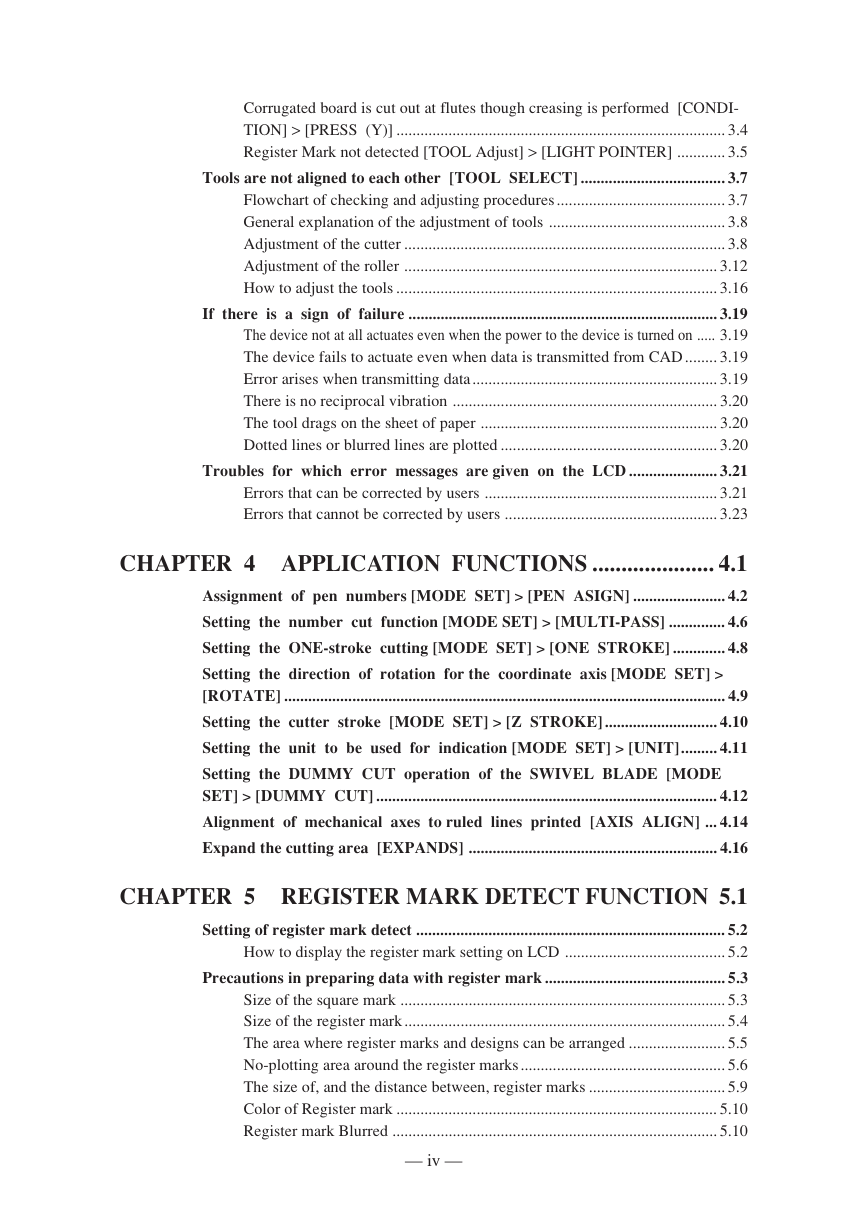
Corrugated board is cut out at flutes though creasing is performed [CONDI- TION] > [PRESS (Y)] .................................................................................. 3.4 Register Mark not detected [TOOL Adjust] > [LIGHT POINTER] ............ 3.5 Tools are not aligned to each other [TOOL SELECT] .................................... 3.7 Flowchart of checking and adjusting procedures .......................................... 3.7 General explanation of the adjustment of tools ............................................ 3.8 Adjustment of the cutter ................................................................................ 3.8 Adjustment of the roller .............................................................................. 3.12 How to adjust the tools ................................................................................ 3.16 If there is a sign of failure ............................................................................. 3.19 The device not at all actuates even when the power to the device is turned on ..... 3.19 The device fails to actuate even when data is transmitted from CAD ........ 3.19 Error arises when transmitting data ............................................................. 3.19 There is no reciprocal vibration .................................................................. 3.20 The tool drags on the sheet of paper ........................................................... 3.20 Dotted lines or blurred lines are plotted ...................................................... 3.20 Troubles for which error messages are given on the LCD ...................... 3.21 Errors that can be corrected by users .......................................................... 3.21 Errors that cannot be corrected by users ..................................................... 3.23 CHAPTER 4 APPLICATION FUNCTIONS ..................... 4.1 Assignment of pen numbers [MODE SET] > [PEN ASIGN] ....................... 4.2 Setting the number cut function [MODE SET] > [MULTI-PASS] .............. 4.6 Setting the ONE-stroke cutting [MODE SET] > [ONE STROKE] ............. 4.8 Setting the direction of rotation for the coordinate axis [MODE SET] > [ROTATE] .............................................................................................................. 4.9 Setting the cutter stroke [MODE SET] > [Z STROKE] ............................ 4.10 Setting the unit to be used for indication [MODE SET] > [UNIT]......... 4.11 Setting the DUMMY CUT operation of the SWIVEL BLADE [MODE SET] > [DUMMY CUT] ..................................................................................... 4.12 Alignment of mechanical axes to ruled lines printed [AXIS ALIGN] ... 4.14 Expand the cutting area [EXPANDS] .............................................................. 4.16 CHAPTER 5 REGISTER MARK DETECT FUNCTION 5.1 Setting of register mark detect ............................................................................. 5.2 How to display the register mark setting on LCD ........................................ 5.2 Precautions in preparing data with register mark ............................................. 5.3 Size of the square mark ................................................................................. 5.3 Size of the register mark ................................................................................ 5.4 The area where register marks and designs can be arranged ........................ 5.5 No-plotting area around the register marks ................................................... 5.6 The size of, and the distance between, register marks .................................. 5.9 Color of Register mark ................................................................................ 5.10 Register mark Blurred ................................................................................. 5.10 — iv —
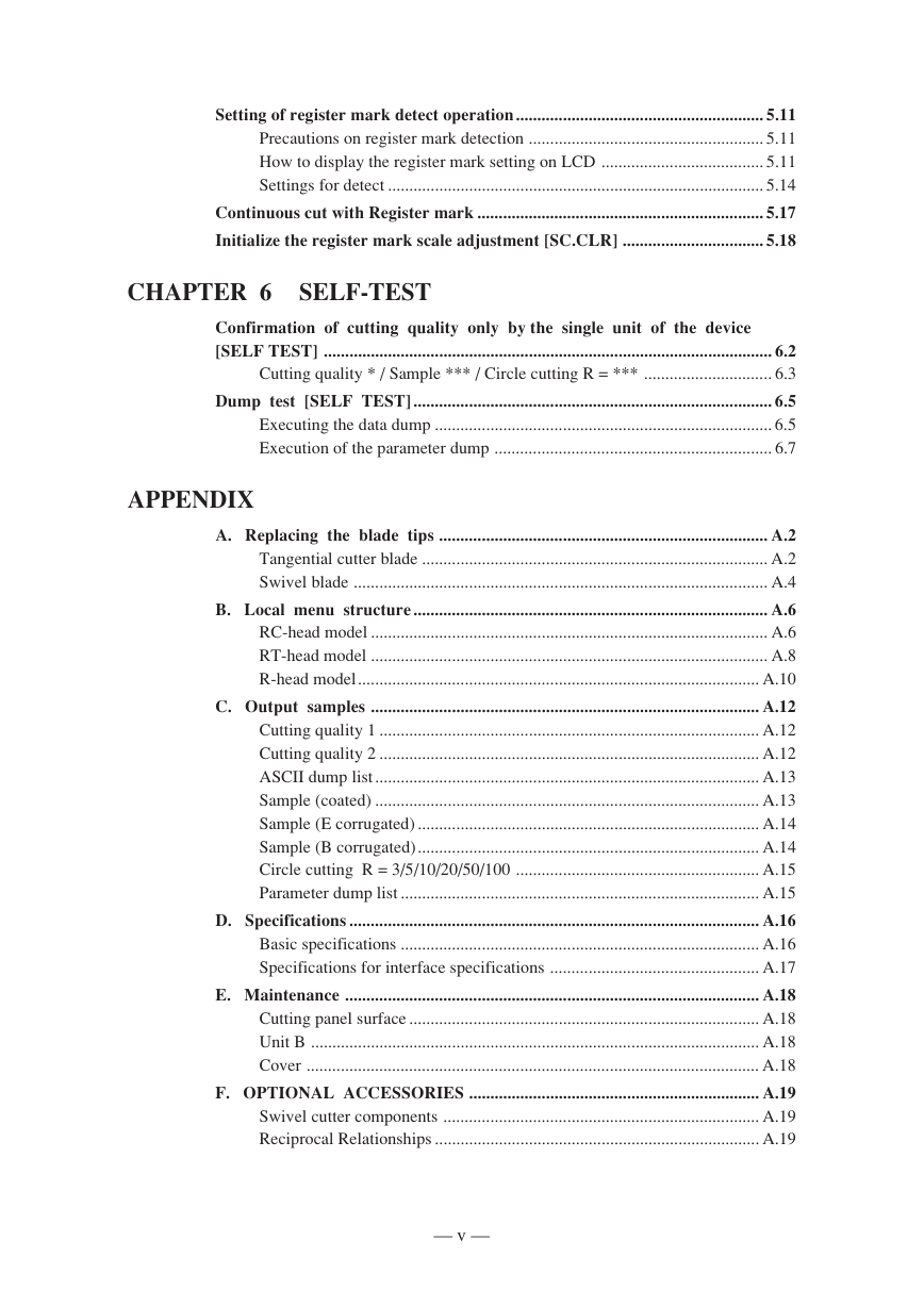
Setting of register mark detect operation.......................................................... 5.11 Precautions on register mark detection ....................................................... 5.11 How to display the register mark setting on LCD ...................................... 5.11 Settings for detect ........................................................................................ 5.14 Continuous cut with Register mark ................................................................... 5.17 Initialize the register mark scale adjustment [SC.CLR] ................................. 5.18 CHAPTER 6 SELF-TEST Confirmation of cutting quality only by the single unit of the device [SELF TEST] ......................................................................................................... 6.2 Cutting quality * / Sample *** / Circle cutting R = *** .............................. 6.3 Dump test [SELF TEST] .................................................................................... 6.5 Executing the data dump ............................................................................... 6.5 Execution of the parameter dump ................................................................. 6.7 APPENDIX A. Replacing the blade tips ............................................................................. A.2 Tangential cutter blade ................................................................................. A.2 Swivel blade ................................................................................................. A.4 B. Local menu structure ................................................................................... A.6 RC-head model ............................................................................................. A.6 RT-head model ............................................................................................. A.8 R-head model.............................................................................................. A.10 C. Output samples ........................................................................................... A.12 Cutting quality 1 ......................................................................................... A.12 Cutting quality 2 ......................................................................................... A.12 ASCII dump list .......................................................................................... A.13 Sample (coated) .......................................................................................... A.13 Sample (E corrugated) ................................................................................ A.14 Sample (B corrugated)................................................................................ A.14 Circle cutting R = 3/5/10/20/50/100 ......................................................... A.15 Parameter dump list .................................................................................... A.15 D. Specifications ................................................................................................ A.16 Basic specifications .................................................................................... A.16 Specifications for interface specifications ................................................. A.17 E. Maintenance ................................................................................................. A.18 Cutting panel surface .................................................................................. A.18 Unit B ......................................................................................................... A.18 Cover .......................................................................................................... A.18 F. OPTIONAL ACCESSORIES .................................................................... A.19 Swivel cutter components .......................................................................... A.19 Reciprocal Relationships ............................................................................ A.19 — v —
ABOUT MODEL NAME The structure of model name is as follows. Head type - Presence of Mark sensor Model name - Size Model Name: CF2 Size 0912 1200 x 900mm 1215 1500 x 1200mm 1218 1800 x 1200mm Head type RC RT Reciprocal cutter unit 2mm Creasing unit Reciprocal cutter unit 5mm Creasing unit Mark sensor N S No mark sensor Mark sensor equipped — vi —
分享到:
收藏