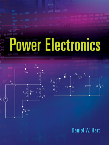
Cover
Title Page
Copyright
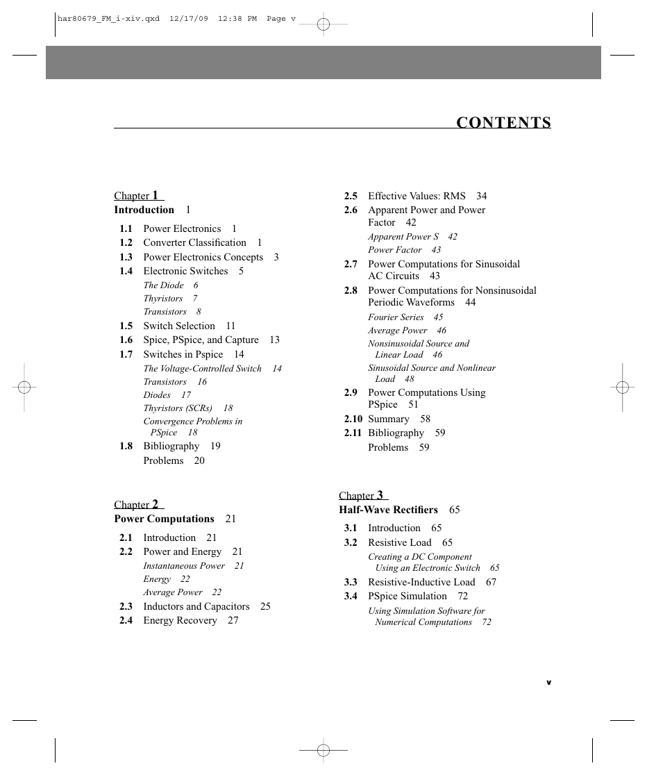
Contents
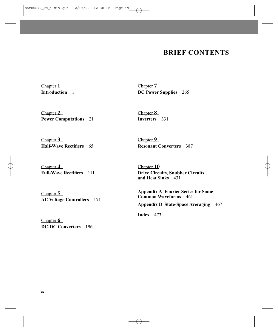
Chapter 1 Introduction
1.1 Power Electronics
1.2 Converter Classification
1.3 Power Electronics Concepts
1.4 Electronic Switches
The Diode
Thyristors
Transistors
1.5 Switch Selection
1.6 Spice, PSpice, and Capture
1.7 Switches in Pspice
The Voltage-Controlled Switch
Transistors
Diodes
Thyristors (SCRs)
Convergence Problems in PSpice
1.8 Bibliography
Problems
Chapter 2 Power Computations
2.1 Introduction
2.2 Power and Energy
Instantaneous Power
Energy
Average Power
2.3 Inductors and Capacitors
2.4 Energy Recovery
2.5 Effective Values: RMS
2.6 Apparent Power and Power Factor
Apparent Power S
Power Factor
2.7 Power Computations for Sinusoidal AC Circuits
2.8 Power Computations for Nonsinusoidal Periodic Waveforms
Fourier Series
Average Power
Nonsinusoidal Source and Linear Load
Sinusoidal Source and Nonlinear Load
2.9 Power Computations Using PSpice
2.10 Summary
2.11 Bibliography
Problems
Chapter 3 Half-Wave Rectifiers
3.1 Introduction
3.2 Resistive Load
Creating a DC Component Using an Electronic Switch
3.3 Resistive-Inductive Load
3.4 PSpice Simulation
Using Simulation Software for Numerical Computations
3.5 RL-Source Load
Supplying Power to a DC Source from an AC Source
3.6 Inductor-Source Load
Using Inductance to Limit Current
3.7 The Freewheeling Diode
Creating a DC Current
Reducing Load Current Harmonics
3.8 Half-Wave Rectifier With a Capacitor Filter
Creating a DC Voltage from an AC Source
3.9 The Controlled Half-Wave Rectifier
Resistive Load
RL Load
RL-Source Load
3.10 PSpice Solutions For Controlled Rectifiers
Modeling the SCR in PSpice
3.11 Commutation
The Effect of Source Inductance
3.12 Summary
3.13 Bibliography
Problems
Chapter 4 Full-Wave Rectifiers
4.1 Introduction
4.2 Single-Phase Full-Wave Rectifiers
The Bridge Rectifier
The Center-Tapped Transformer Rectifier
Resistive Load
RL Load
Source Harmonics
PSpice Simulation
RL-Source Load
Capacitance Output Filter
Voltage Doublers
LC Filtered Output
4.3 Controlled Full-Wave Rectifiers
Resistive Load
RL Load, Discontinuous Current
RL Load, Continuous Current
PSpice Simulation of Controlled Full-Wave Rectifiers
Controlled Rectifier with RL-Source Load
Controlled Single-Phase Converter Operating as an Inverter
4.4 Three-Phase Rectifiers
4.5 Controlled Three-Phase Rectifiers
Twelve-Pulse Rectifiers
The Three-Phase Converter Operating as an Inverter
4.6 DC Power Transmission
4.7 Commutation: The Effect of Source Inductance
Single-Phase Bridge Rectifier
Three-Phase Rectifier
4.8 Summary
4.9 Bibliography
Problems
Chapter 5 AC Voltage Controllers
5.1 Introduction
5.2 The Single-Phase AC Voltage Controller
Basic Operation
Single-Phase Controller with a Resistive Load
Single-Phase Controller with an RL Load
PSpice Simulation of Single-Phase AC Voltage Controllers
5.3 Three-Phase Voltage Controllers
Y-Connected Resistive Load
Y-Connected RL Load
Delta-Connected Resistive Load
5.4 Induction Motor Speed Control
5.5 Static VAR Control
5.6 Summary
5.7 Bibliography
Problems
Chapter 6 DC-DC Converters
6.1 Linear Voltage Regulators
6.2 A Basic Switching Converter
6.3 The Buck (Step-Down) Converter
Voltage and Current Relationships
Output Voltage Ripple
Capacitor Resistance—The Effect on Ripple Voltage
Synchronous Rectification for the Buck Converter
6.4 Design Considerations
6.5 The Boost Converter
Voltage and Current Relationships
Output Voltage Ripple
Inductor Resistance
6.6 The Buck-Boost Converter
Voltage and Current Relationships
Output Voltage Ripple
6.7 The Cuk Converter
6.8 The Single-Ended Primary Inductance Converter (SEPIC)
6.9 Interleaved Converters
6.10 Nonideal Switches and Converter Performance
Switch Voltage Drops
Switching Losses
6.11 Discontinuous-Current Operation
Buck Converter with Discontinuous Current
Boost Converter with Discontinuous Current
6.12 Switched-Capacitor Converters
The Step-Up Switched-Capacitor Converter
The Inverting Switched-Capacitor Converter
The Step-Down Switched-Capacitor Converter
6.13 PSpice Simulation of DC-DC Converters
A Switched PSpice Model
An Averaged Circuit Model
6.14 Summary
6.15 Bibliography
Problems
Chapter 7 DC Power Supplies
7.1 Introduction
7.2 Transformer Models
7.3 The Flyback Converter
Continuous-Current Mode
Discontinuous-Current Mode in the Flyback Converter
Summary of Flyback Converter Operation
7.4 The Forward Converter
Summary of Forward Converter Operation
7.5 The Double-Ended (Two-Switch) Forward Converter
7.6 The Push-Pull Converter
Summary of Push-Pull Operation
7.7 Full-Bridge and Half-Bridge DC-DC Converters
7.8 Current-Fed Converters
7.9 Multiple Outputs
7.10 Converter Selection
7.11 Power Factor Correction
7.12 PSpice Simulation of DC Power Supplies
7.13 Power Supply Control
Control Loop Stability
Small-Signal Analysis
Switch Transfer Function
Filter Transfer Function
Pulse-Width Modulation Transfer Function
Type 2 Error Amplifier with Compensation
Design of a Type 2 Compensated Error Amplifier
PSpice Simulation of Feedback Control
Type 3 Error Amplifier with Compensation
Design of a Type 3 Compensated Error Amplifier
Manual Placement of Poles and Zeros in the Type 3 Amplifier
7.14 PWM Control Circuits
7.15 The AC Line Filter
7.16 The Complete DC Power Supply
7.17 Bibliography
Problems
Chapter 8 Inverters
8.1 Introduction
8.2 The Full-Bridge Converter
8.3 The Square-Wave Inverter
8.4 Fourier Series Analysis
8.5 Total Harmonic Distortion
8.6 PSpice Simulation of Square Wave Inverters
8.7 Amplitude and Harmonic Control
8.8 The Half-Bridge Inverter
8.9 Multilevel Inverters
Multilevel Converters with Independent DC Sources
Equalizing Average Source Power with Pattern Swapping
Diode-Clamped Multilevel Inverters
8.10 Pulse-Width-Modulated Output
Bipolar Switching
Unipolar Switching
8.11 PWM Definitions and Considerations
8.12 PWM Harmonics
Bipolar Switching
Unipolar Switching
8.13 Class D Audio Amplifiers
8.14 Simulation of Pulse-Width-Modulated Inverters
Bipolar PWM
Unipolar PWM
8.15 Three-Phase Inverters
The Six-Step Inverter
PWM Three-Phase Inverters
Multilevel Three-Phase Inverters
8.16 PSpice Simulation of Three-Phase Inverters
Six-Step Three-Phase Inverters
PWM Three-Phase Inverters
8.17 Induction Motor Speed Control
8.18 Summary
8.19 Bibliography
Problems
Chapter 9 Resonant Converters
9.1 Introduction
9.2 A Resonant Switch Converter: Zero-Current Switching
Basic Operation
Output Voltage
9.3 A Resonant Switch Converter: Zero-Voltage Switching
Basic Operation
Output Voltage
9.4 The Series Resonant Inverter
Switching Losses
Amplitude Control
9.5 The Series Resonant DC-DC Converter
Basic Operation
Operation for ω[sub(s)] > ω[sub(o)]
Operation for ω[sub(0)]/2 < ω[sub(s)] < ω[sub(0)]
Operation for ω[sub(s)] < ω[sub(0)]/2
Variations on the Series Resonant DC-DC Converter
9.6 The Parallel Resonant DC-DC Converter
9.7 The Series-Parallel DC-DC Converter
9.8 Resonant Converter Comparison
9.9 The Resonant DC Link Converter
9.10 Summary
9.11 Bibliography
Problems
Chapter 10 Drive Circuits, Snubber Circuits, and Heat Sinks
10.1 Introduction
10.2 MOSFET and IGBT Drive Circuits
Low-Side Drivers
High-Side Drivers
10.3 Bipolar Transistor Drive Circuits
10.4 Thyristor Drive Circuits
10.5 Transistor Snubber Circuits
10.6 Energy Recovery Snubber Circuits
10.7 Thyristor Snubber Circuits
10.8 Heat Sinks and Thermal Management
Steady-State Temperatures
Time-Varying Temperatures
10.9 Summary
10.10 Bibliography
Problems
Appendix A: Fourier Series for Some Common Waveforms
Appendix B: State-Space Averaging
Index


 2023年江西萍乡中考道德与法治真题及答案.doc
 2012年重庆南川中考生物真题及答案.doc
 2013年江西师范大学地理学综合及文艺理论基础考研真题.doc
 2020年四川甘孜小升初语文真题及答案I卷.doc
 2020年注册岩土工程师专业基础考试真题及答案.doc
 2023-2024学年福建省厦门市九年级上学期数学月考试题及答案.doc
 2021-2022学年辽宁省沈阳市大东区九年级上学期语文期末试题及答案.doc
 2022-2023学年北京东城区初三第一学期物理期末试卷及答案.doc
 2018上半年江西教师资格初中地理学科知识与教学能力真题及答案.doc
 2012年河北国家公务员申论考试真题及答案-省级.doc
 2020-2021学年江苏省扬州市江都区邵樊片九年级上学期数学第一次质量检测试题及答案.doc
 2022下半年黑龙江教师资格证中学综合素质真题及答案.doc