AFFDL-TR-79-3032
Volume I
THE USAF STABILITY AND CONTROL DATCOM
Volume I, Users Manual
McDonnell Douglas Astronautics Company
St. Louis Division
St Louis, Missouri 63166
April 1979
Updated by
Public Domain Aeronautical Software
Santa Cruz CA 95061
December 1999
AIR FORCE FLIGHT DYNAMICS LABORATORY
AIR FORCE WRIGHT AERONAUTICAL LABORATORIES
AIR FORCE SYSTEMS COMMAND
WRIGHT-PATTERSON AIR FORCE BASE, OH 45433
Page 1 of 67
�
From AFFDL-TR-79-3032
THE USAF STABILITY AND CONTROL DIGITAL DATCOM
Volume I, Users Manual
SECTION 1
INTRODUCTION
In preliminary design operations, rapid and economical estimations of
aerodynamic stability and control characteristics are frequently required. The
extensive application of complex automated estimation procedures is often
prohibitive in terms of time and computer cost in such an environment. Similar
inefficiencies accompany hand-calculation procedures, which can require
expenditures of significant man-hours, particularly if configuration trade studies
are involved, or if estimates are desired over a range of flight conditions. The
fundamental purpose of the USAF Stability and Control Datcom is to provide a
systematic summary of methods for estimating stability and control characteristics
In preliminary design applications. Consistent with this philosophy, the
development of the Digital Datcom computer program is an approach to provide
rapid and economical estimation of aerodynamic stability and control
characteristics.
Digital Datcom calculates static stability, high-lift and control device, and
dynamic-derivative characteristics using the methods contained in Sections 4
through 7 of Datcom. The computer program also offer a trim option that
computes control deflections and aerodynamic data for vehicle trim at subsonic
Mach numbers.
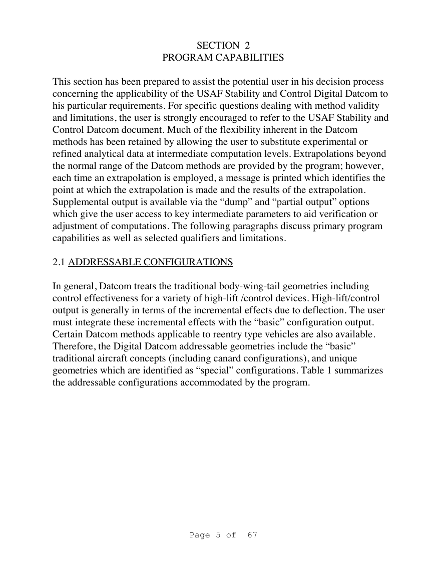
The program has been developed an a modular basis as illustrated in Figure 1.
These modules correspond to the primary building blocks referenced in the
program executive. The modular approach was used because it simplified program
development, testing, and modification or expansion.
This report is the User's Manual for the USAF Stability and Control Digital
Datcom. Potential users are directed to Section 2 for an overview of program
capabilities. Section 3 provides input definitions, with basic configuration
geometry modeling techniques presented in Section 4. Analyses of special
configurations are treated in Section 5. Section 6 discusses the available output
Page 2 of 67
�
data. The appendices discuss namelist coding rules, airfoil section characteristic
estimation methods with supplemental data, and a list of geometric and
aerodynamic variables available as supplemental output. A self-contained user's
kit is included to aid the user in setting up inputs to the program.
Even though the development of Digital Datcom was pursued with the sole
objective of translating the Datcom methods into an efficient, user-oriented
computer program, differences between Datcom and Digital Datcom do exist.
Such is the primary subject of Volume II, Implementation of Datcom Methods,
which contains the correspondence between Datcom methods and program
formulation. This volume also defines the program implementation requirements.
The listing of the computer program is contained on microfiche as a supplement to
this report. Modifications, extensions, and limitations of Datcom methods as
incorporated in Digital Datcom are discussed throughout the report.
Users should refer to Datcom for the limitations of methods involved. However,
potential users are forewarned that Datcom drag methods are not recommended for
performance. Where more than one Datcom method exists, Volume II indicates
which method or methods are employed in Digita1 Datcom.
Direct all program inquiries to AFFDL FGC, Wright-Patterson Air Force Base,
OH 45433; phone (513) 255-4315.
Page 3 of 67
�
MASTER ROUTINES
Main Programs
Executive Subroutines
Utility Subroutines
METHOD MODULES
Performs the executive functions of organizing and directing the
operations performed by other program components.
Performs user-oriented non-method operations such as ordering input
data, logic switching, input error analysis, and output format selection.
Performs standard mathematical tasks repetitively performed by method
subroutines.
SUBSONIC
TRANSONIC
SUPERSONIC
MODULE 1
CHARACTERISTICS AT
ANGLE OF ATTACK
MODULE 3
CHARACTERISTICS AT
ANGLE OF ATTACK
MODULE 5
CHARACTERISTICS AT
ANGLE OF ATTACK
MODULE 2
CHARACTERISTICS IN
SIDESLIP
MODULE 4
CHARACTERISTICS IN
SIDESLIP
MODULE 6
CHARACTERISTICS IN
SIDESLIP
MODULE 10
DYNAMIC DERIVATIVES
MODULE 11
HIGH LIFT AND CONTROL DEVICES
MODULE 7
TRIM OPTION
SPECIAL
CONFIGURATIONS
MODULE 7
LOW ASPECT RATIO
WING-BODY AT
SUBSONIC SPEEDS
MODULE 8
AERODYNAMIC
CONTROL
EFFECTIVENESS AT
HYPERSONIC SPEEDS
MODULE 9
TRAVERSE-JET
CONTROL
EFFECTIVENESS AT
HYPERSONIC SPEEDS
FIGURE 1 - DIGITAL DATCOM MODULES
Page 4 of 67
�
SECTION 2
PROGRAM CAPABILITIES
This section has been prepared to assist the potential user in his decision process
concerning the applicability of the USAF Stability and Control Digital Datcom to
his particular requirements. For specific questions dealing with method validity
and limitations, the user is strongly encouraged to refer to the USAF Stability and
Control Datcom document. Much of the flexibility inherent in the Datcom
methods has been retained by allowing the user to substitute experimental or
refined analytical data at intermediate computation levels. Extrapolations beyond
the normal range of the Datcom methods are provided by the program; however,
each time an extrapolation is employed, a message is printed which identifies the
point at which the extrapolation is made and the results of the extrapolation.
Supplemental output is available via the “dump” and “partial output” options
which give the user access to key intermediate parameters to aid verification or
adjustment of computations. The following paragraphs discuss primary program
capabilities as well as selected qualifiers and limitations.
2.1 ADDRESSABLE CONFIGURATIONS
In general, Datcom treats the traditional body-wing-tail geometries including
control effectiveness for a variety of high-lift /control devices. High-lift/control
output is generally in terms of the incremental effects due to deflection. The user
must integrate these incremental effects with the “basic” configuration output.
Certain Datcom methods applicable to reentry type vehicles are also available.
Therefore, the Digital Datcom addressable geometries include the “basic”
traditional aircraft concepts (including canard configurations), and unique
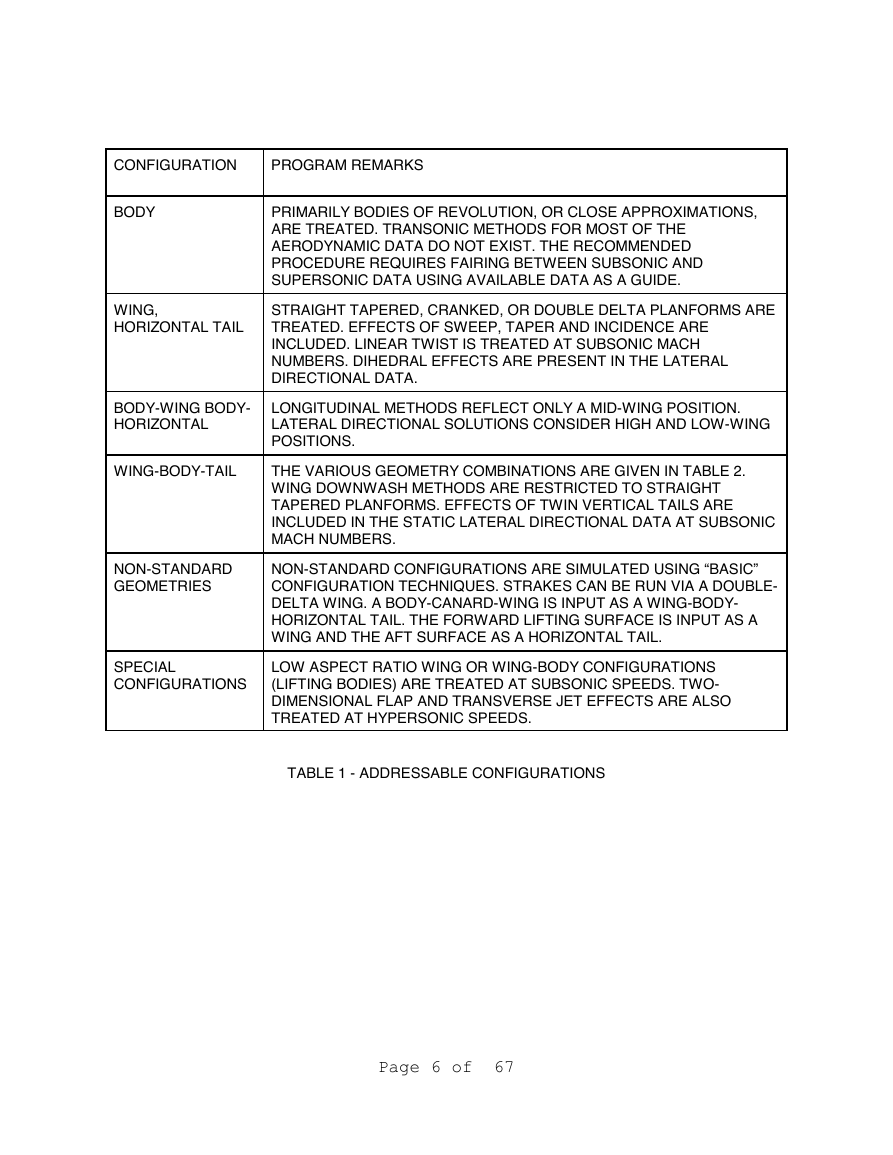
geometries which are identified as “special” configurations. Table 1 summarizes
the addressable configurations accommodated by the program.
Page 5 of 67
�
CONFIGURATION
PROGRAM REMARKS
BODY
WING,
HORIZONTAL TAIL
PRIMARILY BODIES OF REVOLUTION, OR CLOSE APPROXIMATIONS,
ARE TREATED. TRANSONIC METHODS FOR MOST OF THE
AERODYNAMIC DATA DO NOT EXIST. THE RECOMMENDED
PROCEDURE REQUIRES FAIRING BETWEEN SUBSONIC AND
SUPERSONIC DATA USING AVAILABLE DATA AS A GUIDE.
STRAIGHT TAPERED, CRANKED, OR DOUBLE DELTA PLANFORMS ARE
TREATED. EFFECTS OF SWEEP, TAPER AND INCIDENCE ARE
INCLUDED. LINEAR TWIST IS TREATED AT SUBSONIC MACH
NUMBERS. DIHEDRAL EFFECTS ARE PRESENT IN THE LATERAL
DIRECTIONAL DATA.
BODY-WING BODY-
HORIZONTAL
LONGITUDINAL METHODS REFLECT ONLY A MID-WING POSITION.
LATERAL DIRECTIONAL SOLUTIONS CONSIDER HIGH AND LOW-WING
POSITIONS.
WING-BODY-TAIL
NON-STANDARD
GEOMETRIES
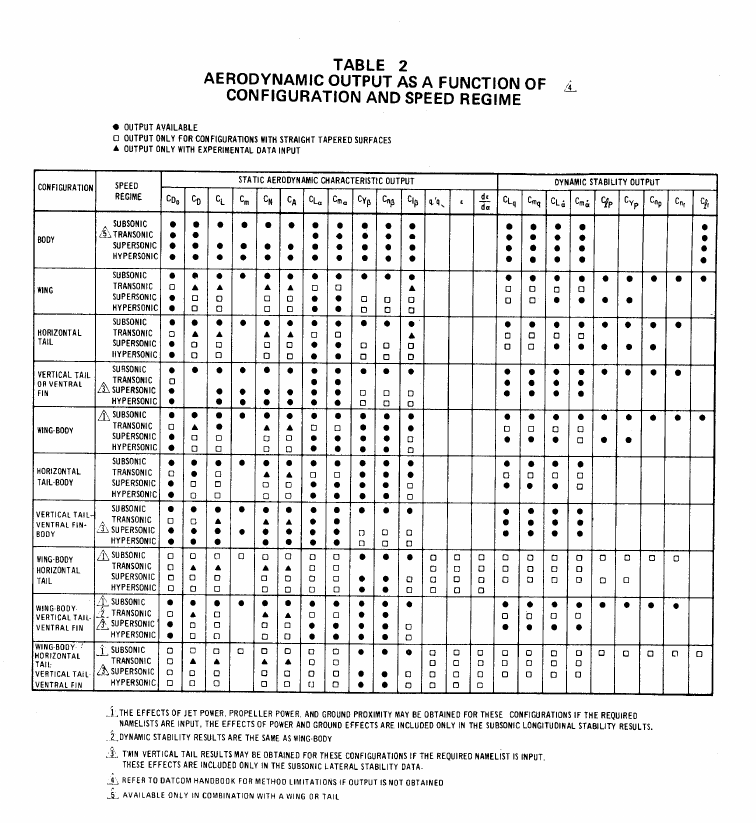
THE VARIOUS GEOMETRY COMBINATIONS ARE GIVEN IN TABLE 2.
WING DOWNWASH METHODS ARE RESTRICTED TO STRAIGHT
TAPERED PLANFORMS. EFFECTS OF TWIN VERTICAL TAILS ARE
INCLUDED IN THE STATIC LATERAL DIRECTIONAL DATA AT SUBSONIC
MACH NUMBERS.
NON-STANDARD CONFIGURATIONS ARE SIMULATED USING “BASIC”
CONFIGURATION TECHNIQUES. STRAKES CAN BE RUN VIA A DOUBLE-
DELTA WING. A BODY-CANARD-WING IS INPUT AS A WING-BODY-
HORIZONTAL TAIL. THE FORWARD LIFTING SURFACE IS INPUT AS A
WING AND THE AFT SURFACE AS A HORIZONTAL TAIL.
SPECIAL
CONFIGURATIONS
LOW ASPECT RATIO WING OR WING-BODY CONFIGURATIONS
(LIFTING BODIES) ARE TREATED AT SUBSONIC SPEEDS. TWO-
DIMENSIONAL FLAP AND TRANSVERSE JET EFFECTS ARE ALSO
TREATED AT HYPERSONIC SPEEDS.
TABLE 1 - ADDRESSABLE CONFIGURATIONS
Page 6 of 67
�
�
2.2 BASIC CONFIGURATION DATA
The capabilities discussed below apply to basic configurations, i.e., traditional
body-wing-tail concepts. A detailed summary of output as a function of
configuration and speed regime is presented in Table 2. Note that transonic output
can be expanded through the use of data substitution (Sections 3.2 and 4.5).
Typical output for these configurations are presented in section 6.
2.2.1 Static Stability Characteristics
The longitudinal and lateral-directional stability characteristics provided by the
Datcom and the Digital Datcom are in the stability-axis system. Body-axis normal-
force and axial-force coefficients are also included in the output for convenience
of the user. For those speed regimes and configurations where Datcom methods
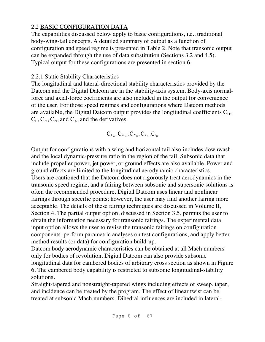
are available, the Digital Datcom output provides the longitudinal coefficients CD,
CL, Cm, CN, and CA, and the derivatives
C
L
α
,
C
m
α
,
C
,
C
,
C
l
β
n
β
Y
β
Output for configurations with a wing and horizontal tail also includes downwash
and the local dynamic-pressure ratio in the region of the tail. Subsonic data that
include propeller power, jet power, or ground effects are also available. Power and
ground effects are limited to the longitudinal aerodynamic characteristics.
Users are cautioned that the Datcom does not rigorously treat aerodynamics in the
transonic speed regime, and a fairing between subsonic and supersonic solutions is
often the recommended procedure. Digital Datcom uses linear and nonlinear
fairings through specific points; however, the user may find another fairing more
acceptable. The details of these fairing techniques are discussed in Volume II,
Section 4. The partial output option, discussed in Section 3.5, permits the user to
obtain the information necessary for transonic fairings. The experimental data
input option allows the user to revise the transonic fairings on configuration
components, perform parametric analyses on test configurations, and apply better
method results (or data) for configuration build-up.
Datcom body aerodynamic characteristics can be obtained at all Mach numbers
only for bodies of revolution. Digital Datcom can also provide subsonic
longitudinal data for cambered bodies of arbitrary cross section as shown in Figure
6. The cambered body capability is restricted to subsonic longitudinal-stability
solutions.
Straight-tapered and nonstraight-tapered wings including effects of sweep, taper,
and incidence can be treated by the program. The effect of linear twist can be
treated at subsonic Mach numbers. Dihedral influences are included in lateral-
Page 8 of 67
�


 2023年江西萍乡中考道德与法治真题及答案.doc
 2012年重庆南川中考生物真题及答案.doc
 2013年江西师范大学地理学综合及文艺理论基础考研真题.doc
 2020年四川甘孜小升初语文真题及答案I卷.doc
 2020年注册岩土工程师专业基础考试真题及答案.doc
 2023-2024学年福建省厦门市九年级上学期数学月考试题及答案.doc
 2021-2022学年辽宁省沈阳市大东区九年级上学期语文期末试题及答案.doc
 2022-2023学年北京东城区初三第一学期物理期末试卷及答案.doc
 2018上半年江西教师资格初中地理学科知识与教学能力真题及答案.doc
 2012年河北国家公务员申论考试真题及答案-省级.doc
 2020-2021学年江苏省扬州市江都区邵樊片九年级上学期数学第一次质量检测试题及答案.doc
 2022下半年黑龙江教师资格证中学综合素质真题及答案.doc