.
1
B
-
8
6
5
-
/
A
I
E
A
I
T
ANSI/TIA/EIA-568-B.1-2001
Approved: April 12, 2001
TIA/EIA
STANDARD
Commercial Building
Telecommunications Cabling Standard
Part 1: General Requirements
TIA/EIA-568-B.1
(Revision of TIA/EIA-568-A)
MAY 2001
TELECOMMUNICATIONS INDUSTRY ASSOCIATION
The Telecommunications Industry Association
represents the communications sector of
�
NOTICE
TIA/EIA Engineering Standards and Publications are designed to serve the public interest through
eliminating misunderstandings between manufacturers and purchasers, facilitating interchangeability and
improvement of products, and assisting the purchaser in selecting and obtaining with minimum delay the
proper product for his particular need. Existence of such Standards and Publications shall not in any
respect preclude any member or nonmember of TIA/EIA from manufacturing or selling products not
conforming to such Standards and Publications, nor shall the existence of such Standards and
Publications preclude their voluntary use by those other than TIA/EIA members, whether the standard is
to be used either domestically or internationally.
Standards and Publications are adopted by TIA/EIA in accordance with the American National
Standards Institute (ANSI) patent policy. By such action, TIA/EIA does not assume any liability to any
patent owner, nor does it assume any obligation whatever to parties adopting the Standard or
Publication.
This Standard does not purport to address all safety problems associated with its use or all applicable
regulatory requirements. It is the responsibility of the user of this Standard to establish appropriate
safety and health practices and to determine the applicability of regulatory limitations before its use.
(From Standards Proposal Nos.4425-B, 4425-B-1 and 4425-B-2, formulated under the cognizance of the
TIA TR-42 Committee on User Premises Telecommunications Infrastructure.)
Published by
TELECOMMUNICATIONS INDUSTRY ASSOCIATION 2001
Standards and Technology Department
2500 Wilson Boulevard
Arlington, VA 22201
PRICE: Please refer to current Catalog of
EIA ELECTRONIC INDUSTRIES ALLIANCE STANDARDS and ENGINEERING
PUBLICATIONS or call Global Engineering Documents, USA and Canada
(1-800-854-7179) International (303-397-7956)
All rights reserved
Printed in U.S.A.
�
PLEASE!
DON'T VIOLATE
THE
LAW!
This document is copyrighted by the TIA and may not be reproduced without
permission.
Organizations may obtain permission to reproduce a limited number of copies
through entering into a license agreement. For information, contact:
U.S.A. and Canada 1-800-854-7179, International (303) 397-7956
Englewood, CO 80112-5704 or call
Global Engineering Documents
15 Inverness Way East
�
�
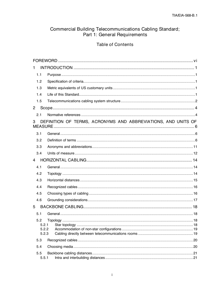
TIA/EIA-568-B.1
Commercial Building Telecommunications Cabling Standard;
Part 1: General Requirements
Table of Contents
FOREWORD ........................................................................................................................... vi
1
INTRODUCTION .............................................................................................................. 1
Purpose ..........................................................................................................................1
1.1
Specification of criteria......................................................................................................1
1.2
1.3 Metric equivalents of US customary units ...........................................................................1
Life of this Standard..........................................................................................................1
1.4
1.5
Telecommunications cabling system structure....................................................................2
2 Scope................................................................................................................................. 4
2.1 Normative references ........................................................................................................4
3 DEFINITION OF TERMS, ACRONYMS AND ABBREVIATIONS, AND UNITS OF
MEASURE ................................................................................................................................ 6
3.1 General ...........................................................................................................................6
3.2 Definition of terms ............................................................................................................6
3.3
Acronyms and abbreviations............................................................................................11
3.4 Units of measure............................................................................................................12
4 HORIZONTAL CABLING................................................................................................ 14
4.1 General .........................................................................................................................14
4.2
Topology .......................................................................................................................14
4.3 Horizontal distances .......................................................................................................15
4.4 Recognized cables .........................................................................................................16
4.5 Choosing types of cabling ...............................................................................................16
4.6 Grounding considerations................................................................................................17
5 BACKBONE CABLING................................................................................................... 18
5.1 General .........................................................................................................................18
Topology .......................................................................................................................18
5.2
Star topology ..........................................................................................................18
Accommodation of non-star configurations .................................................................19
Cabling directly between telecommunications rooms ..................................................19
5.3 Recognized cables .........................................................................................................20
5.4 Choosing media .............................................................................................................20
Backbone cabling distances............................................................................................21
5.5
Intra and interbuilding distances ................................................................................21
5.2.1
5.2.2
5.2.3
5.5.1
i
�
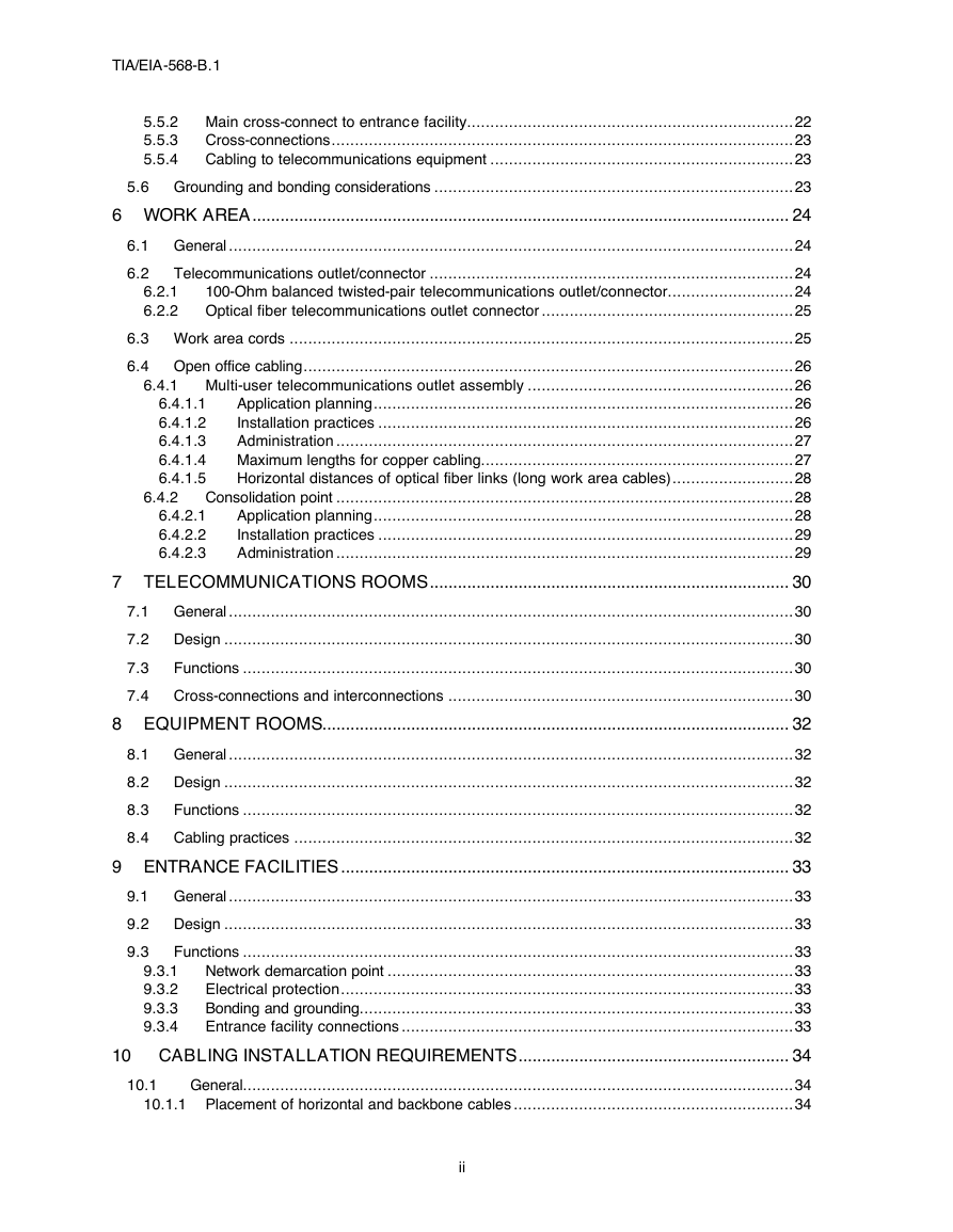
TIA/EIA-568-B.1
6.4.2
6.4.2.1
6.4.2.2
6.4.2.3
6.4.1.1
6.4.1.2
6.4.1.3
6.4.1.4
6.4.1.5
5.5.2 Main cross-connect to entrance facility......................................................................22
Cross-connections...................................................................................................23
5.5.3
5.5.4
Cabling to telecommunications equipment .................................................................23
5.6 Grounding and bonding considerations .............................................................................23
6 WORK AREA................................................................................................................... 24
6.1 General .........................................................................................................................24
6.2
Telecommunications outlet/connector ..............................................................................24
6.2.1
100-Ohm balanced twisted-pair telecommunications outlet/connector...........................24
6.2.2 Optical fiber telecommunications outlet connector ......................................................25
6.3 Work area cords ............................................................................................................25
6.4 Open office cabling.........................................................................................................26
6.4.1 Multi-user telecommunications outlet assembly .........................................................26
Application planning..........................................................................................26
Installation practices .........................................................................................26
Administration ..................................................................................................27
Maximum lengths for copper cabling...................................................................27
Horizontal distances of optical fiber links (long work area cables)..........................28
Consolidation point ..................................................................................................28
Application planning..........................................................................................28
Installation practices .........................................................................................29
Administration ..................................................................................................29
7 TELECOMMUNICATIONS ROOMS............................................................................. 30
7.1 General .........................................................................................................................30
7.2 Design ..........................................................................................................................30
7.3
Functions ......................................................................................................................30
7.4 Cross-connections and interconnections ..........................................................................30
8 EQUIPMENT ROOMS.................................................................................................... 32
8.1 General .........................................................................................................................32
8.2 Design ..........................................................................................................................32
8.3
Functions ......................................................................................................................32
8.4 Cabling practices ...........................................................................................................32
9 ENTRANCE FACILITIES ................................................................................................ 33
9.1 General .........................................................................................................................33
9.2 Design ..........................................................................................................................33
Functions ......................................................................................................................33
9.3
Network demarcation point .......................................................................................33
Electrical protection.................................................................................................33
Bonding and grounding.............................................................................................33
Entrance facility connections ....................................................................................33
10 CABLING INSTALLATION REQUIREMENTS.......................................................... 34
General......................................................................................................................34
10.1.1 Placement of horizontal and backbone cables ............................................................34
9.3.1
9.3.2
9.3.3
9.3.4
10.1
ii
�
TIA/EIA-568-B.1
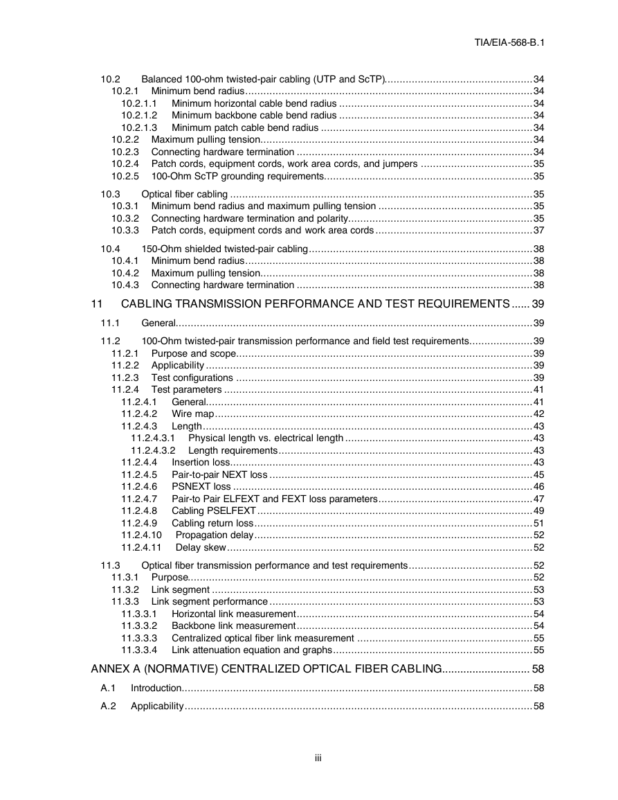
10.2
10.3
10.4
11.1
11.2
Balanced 100-ohm twisted-pair cabling (UTP and ScTP).................................................34
10.2.1 Minimum bend radius...............................................................................................34
10.2.1.1 Minimum horizontal cable bend radius ................................................................34
10.2.1.2 Minimum backbone cable bend radius ................................................................34
10.2.1.3 Minimum patch cable bend radius ......................................................................34
10.2.2 Maximum pulling tension..........................................................................................34
10.2.3 Connecting hardware termination ..............................................................................34
10.2.4 Patch cords, equipment cords, work area cords, and jumpers .....................................35
10.2.5 100-Ohm ScTP grounding requirements.....................................................................35
Optical fiber cabling ....................................................................................................35
10.3.1 Minimum bend radius and maximum pulling tension ...................................................35
10.3.2 Connecting hardware termination and polarity.............................................................35
10.3.3 Patch cords, equipment cords and work area cords ....................................................37
150-Ohm shielded twisted-pair cabling..........................................................................38
10.4.1 Minimum bend radius...............................................................................................38
10.4.2 Maximum pulling tension..........................................................................................38
10.4.3 Connecting hardware termination ..............................................................................38
11 CABLING TRANSMISSION PERFORMANCE AND TEST REQUIREMENTS ...... 39
General......................................................................................................................39
100-Ohm twisted-pair transmission performance and field test requirements.....................39
11.2.1 Purpose and scope..................................................................................................39
11.2.2 Applicability ............................................................................................................39
11.2.3 Test configurations ..................................................................................................39
11.2.4 Test parameters ......................................................................................................41
11.2.4.1 General............................................................................................................41
11.2.4.2 Wire map.........................................................................................................42
11.2.4.3
Length.............................................................................................................43
11.2.4.3.1 Physical length vs. electrical length ..............................................................43
11.2.4.3.2 Length requirements....................................................................................43
11.2.4.4
Insertion loss....................................................................................................43
11.2.4.5 Pair-to-pair NEXT loss .......................................................................................45
11.2.4.6 PSNEXT loss ...................................................................................................46
11.2.4.7 Pair-to Pair ELFEXT and FEXT loss parameters...................................................47
11.2.4.8 Cabling PSELFEXT ...........................................................................................49
11.2.4.9 Cabling return loss............................................................................................51
11.2.4.10 Propagation delay............................................................................................52
11.2.4.11 Delay skew.....................................................................................................52
Optical fiber transmission performance and test requirements.........................................52
11.3.1 Purpose..................................................................................................................52
11.3.2 Link segment ..........................................................................................................53
11.3.3 Link segment performance .......................................................................................53
11.3.3.1 Horizontal link measurement..............................................................................54
11.3.3.2 Backbone link measurement..............................................................................54
11.3.3.3 Centralized optical fiber link measurement ..........................................................55
Link attenuation equation and graphs..................................................................55
11.3.3.4
ANNEX A (NORMATIVE) CENTRALIZED OPTICAL FIBER CABLING............................. 58
A.1
Introduction....................................................................................................................58
A.2 Applicability...................................................................................................................58
11.3
iii
�
TIA/EIA-568-B.1
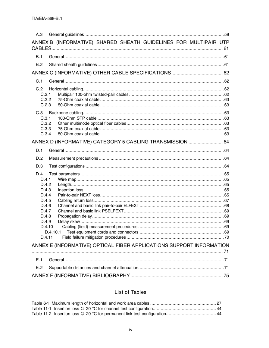
A.3 General guidelines..........................................................................................................58
ANNEX B (INFORMATIVE) SHARED SHEATH GUIDELINES FOR MULTIPAIR UTP
CABLES.................................................................................................................................. 61
B.1 General .........................................................................................................................61
B.2 Shared sheath guidelines ................................................................................................61
ANNEX C (INFORMATIVE) OTHER CABLE SPECIFICATIONS....................................... 62
C.1 General .........................................................................................................................62
C.2 Horizontal cabling...........................................................................................................62
C.2.1 Multipair 100-ohm twisted-pair cables ........................................................................62
C.2.2
75-Ohm coaxial cable ..............................................................................................63
50-Ohm coaxial cable ..............................................................................................63
C.2.3
C.3 Backbone cabling...........................................................................................................63
C.3.1
100-Ohm STP cable ................................................................................................63
C.3.2 Other multimode optical fiber cables..........................................................................63
75-Ohm coaxial cable ..............................................................................................63
C.3.3
C.3.4
50-Ohm coaxial cable ..............................................................................................63
ANNEX D (INFORMATIVE) CATEGORY 5 CABLING TRANSMISSION .......................... 64
D.1 General .........................................................................................................................64
D.2 Measurement precautions ...............................................................................................64
D.3
Test configurations .........................................................................................................64
Test parameters .............................................................................................................65
D.4
D.4.1 Wire map................................................................................................................65
Length....................................................................................................................65
D.4.2
D.4.3
Insertion loss ..........................................................................................................65
D.4.4
Pair-to-pair NEXT loss..............................................................................................65
D.4.5 Cabling return loss...................................................................................................67
D.4.6 Channel and basic link pair-to-pair ELFEXT ................................................................68
D.4.7 Channel and basic link PSELFEXT............................................................................69
D.4.8
Propagation delay....................................................................................................69
D.4.9 Delay skew.............................................................................................................69
Cabling (field) measurement procedures .................................................................69
D.4.10
D.4.10.1 Test equipment cords and connectors ................................................................69
Field failure mitigation procedures ..........................................................................70
ANNEX E (INFORMATIVE) OPTICAL FIBER APPLICATIONS SUPPORT INFORMATION
................................................................................................................................................. 71
E.1 General .........................................................................................................................71
E.2 Supportable distances and channel attenuation.................................................................71
ANNEX F (INFORMATIVE) BIBLIOGRAPHY ...................................................................... 75
D.4.11
List of Tables
Table 6-1 Maximum length of horizontal and work area cables .................................................. 27
Table 11-1 Insertion loss @ 20 °C for channel test configuration................................................ 44
Table 11-2 Insertion loss @ 20 °C for permanent link test configuration...................................... 44
iv
�




 2023年江西萍乡中考道德与法治真题及答案.doc
 2012年重庆南川中考生物真题及答案.doc
 2013年江西师范大学地理学综合及文艺理论基础考研真题.doc
 2020年四川甘孜小升初语文真题及答案I卷.doc
 2020年注册岩土工程师专业基础考试真题及答案.doc
 2023-2024学年福建省厦门市九年级上学期数学月考试题及答案.doc
 2021-2022学年辽宁省沈阳市大东区九年级上学期语文期末试题及答案.doc
 2022-2023学年北京东城区初三第一学期物理期末试卷及答案.doc
 2018上半年江西教师资格初中地理学科知识与教学能力真题及答案.doc
 2012年河北国家公务员申论考试真题及答案-省级.doc
 2020-2021学年江苏省扬州市江都区邵樊片九年级上学期数学第一次质量检测试题及答案.doc
 2022下半年黑龙江教师资格证中学综合素质真题及答案.doc