设计题目: 顺序延时关断三盏灯开关
院
系: 电子信息与电气工程系
学生姓名:
学
号:
200902070006
专业班级: 09 电子信息工程(专升本)
2010 年 10 月 04 日
�
顺序延时关断三盏灯开关
1. 设计背景和设计方案
设计一个开关装置,该开关装置在第一次按下按钮 k 时,三盏灯 x、y 和 z 同时点亮;
当再次按下按钮 k 是,x 灯立刻熄灭;y 灯 5s 后熄灭,在 y 灯熄灭 8s 后,z 灯熄灭。
1.1 设计原理框图与状态图
由设计要求,该数字系统的原理框图如图—1 所示。按下按钮 k 是,输出低电平。
根据功能要求,可以画出如图—2 所示的状态图。
图—1 顺数延时关断三盏灯开关的原理框图
图—2 顺数延时关断三盏灯开关的状态图
1.2 设计方法
(1) 图形输入法:使用图形方式输入数字系统,底层和顶层模块都用图形输入;
(2) 硬件描述语言输入法:使用硬件描述语言 VHDL 或 Verilog HDL 输入数字系
统进行设计的方法,底层和顶层模块都使用硬件描述语言进行描述;
(3) 混合输入法:使用硬件描述语言输入底层模块,使用图形输入顶层模块。
2. 方案实施
本设计课题使用混合输入法设计该数字系统。
�
根据系统要求,该系统分为状态机、5s 计数器、8s 计数器和译码器 4 个模块。
2.1 状态机设计
(1) 用 VHDL 描述状态机
首先启动软件,然后创建新文件,根据图—2 所示的状态图,在文本编辑窗口输入
状态机的 VHDL 语言描述,如下所示。
library ieee;
use ieee.std_logic_1164.all;
use ieee.std_logic_unsigned.all;
entity state is
port(td5,td8,clk,k:in std_logic;
x,y,z,t5,t8:out std_logic);
end;
architecture state_arch of state is
type zt_type is (z0,z1,z2,z3,z4);
signal zt_now,zt_next:zt_type;
begin
n1:process(clk)
begin
if clk'event and clk='1' then
zt_now<=zt_next;
end if;
end process;
n2:process(td5,td8,k,zt_now)
begin
case zt_now is
when z0=> x<='0';y<='0';z<='0';t5<='0';t8<='0';
if k='0' then zt_next<=z1;
else zt_next<=z0;
end if;
when z1=> x<='1';y<='1';z<='1';t5<='0';t8<='0';
if k='1' then zt_next<=z2;
�
else zt_next<=z1;
end if;
when z2=> x<='1';y<='1';z<='1';t5<='0';t8<='0';
if k='0' then zt_next<=z3;
else zt_next<=z2;
end if;
when z3=> x<='0';y<='1';z<='1';t5<='1';t8<='0';
if td5='1' then zt_next<=z4;
else zt_next<=z3;
end if;
when z4=> x<='0';y<='0';z<='1';t5<='0';t8<='1';
if td8='1' then zt_next<=z0;
else zt_next<=z4;
end if;
when others=>x<='0';y<='0';z<='0';t5<='0';t8<='0';zt_next<=z0;
end case;
end process;
end state_arch;
程序运行结束后生成状态机模块,且此状态机的功能完全满足实验的具体要求。
程序运行正确后,运用调用功能生成调用模块,以便在顶层设计时调用。
仿真结果如图—3 所示
图—3 状态机的仿真结果
可以看出,在输入信号 k 的作用之下,状态开始从状态 0 转换到状态 3;随后 td5
�
的高电平使状态传换到 4;td8 信号使状态机从状态 4 返回到状态 0。在状态 0,输出 x、
y 和 z 都是低电平(表示三盏灯灭);在状态 1 和 2,输出 x、y 和 z 都是高电平(表示
三盏灯亮);在状态 3,x 灯灭;在状态 4,x、y 灯灭;最后,返回状态 0,三盏灯同时
灭。
2.2 5s 减法计数器模块设计
5s 减法计数器用于 5s 定时,设计方法与状态机的设计相同。
library ieee;
use ieee.std_logic_1164.all;
use ieee.std_logic_unsigned.all;
entity jishu5 is
port(t5,clk:in std_logic;
td5:out std_logic;
shuchu:out std_logic_vector(0 to 3));
end;
architecture ds5_arch of jishu5 is
signal qq:std_logic_vector(0 to 3);
begin
process(clk,t5)
begin
if t5='0' then qq<="0101";
elsif clk'event and clk='1' then
if qq/="0000" then qq<=qq-1;
else qq<=qq;
end if;
end if;
end process;
td5<='1' when qq="0000" else '0';
shuchu<=qq(0 to 3);
end ds5_arch;
程序运行结束后生成 5s 减法计数器模块,且此减法计数器的功能完全满足实验的具
体要求。
�
程序运行正确后,运用调用功能生成调用模块,以便在顶层设计时调用。
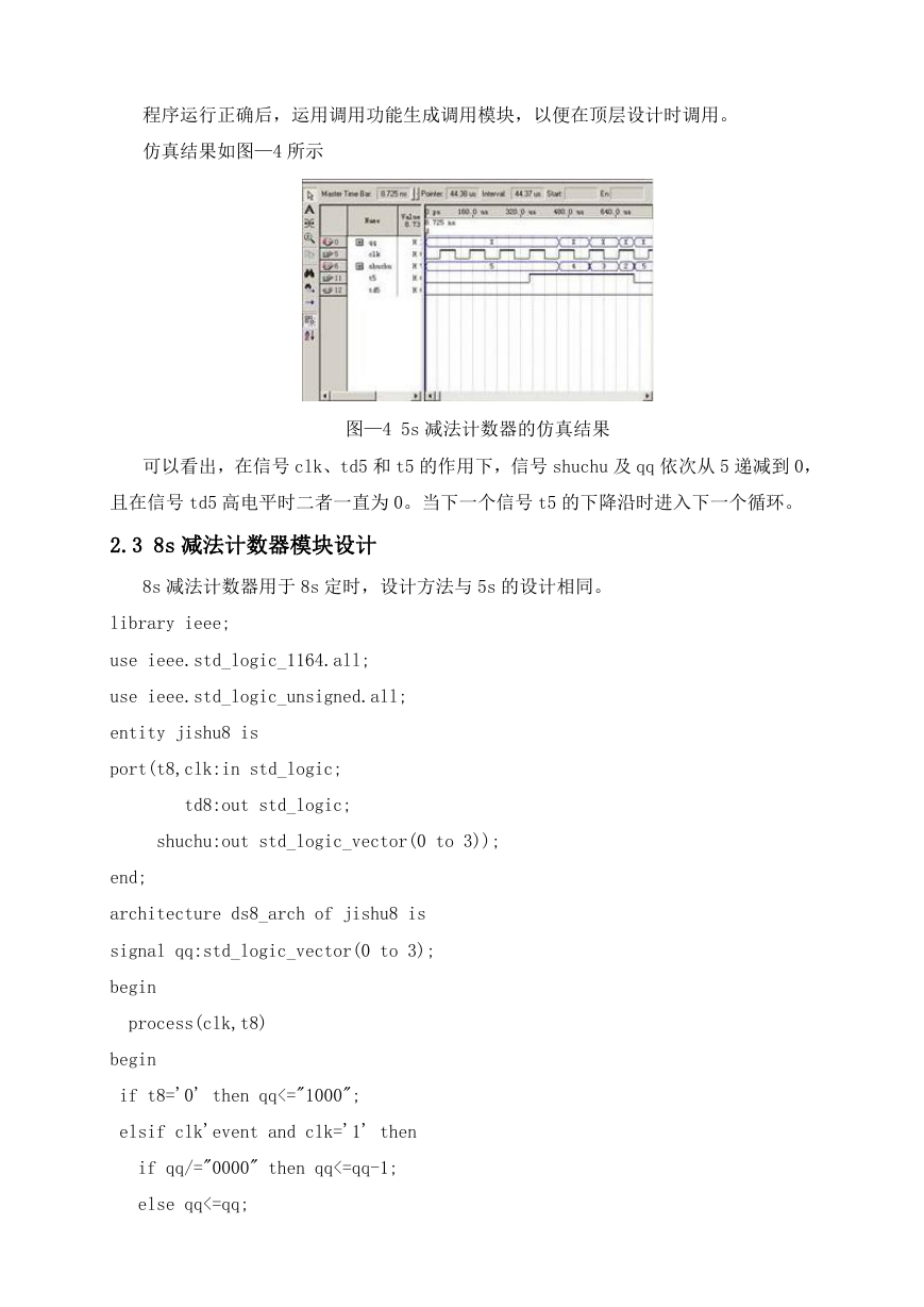
仿真结果如图—4 所示
图—4 5s 减法计数器的仿真结果
可以看出,在信号 clk、td5 和 t5 的作用下,信号 shuchu 及 qq 依次从 5 递减到 0,
且在信号 td5 高电平时二者一直为 0。当下一个信号 t5 的下降沿时进入下一个循环。
2.3 8s 减法计数器模块设计
8s 减法计数器用于 8s 定时,设计方法与 5s 的设计相同。
library ieee;
use ieee.std_logic_1164.all;
use ieee.std_logic_unsigned.all;
entity jishu8 is
port(t8,clk:in std_logic;
td8:out std_logic;
shuchu:out std_logic_vector(0 to 3));
end;
architecture ds8_arch of jishu8 is
signal qq:std_logic_vector(0 to 3);
begin
process(clk,t8)
begin
if t8='0' then qq<="1000";
elsif clk'event and clk='1' then
if qq/="0000" then qq<=qq-1;
else qq<=qq;
�
end if;
end if;
end process;
td8<='1' when qq="0000" else '0';
shuchu<=qq(0 to 3);
end ds8_arch;
程序运行结束后生成 8s 减法计数器模块,且此减法计数器的功能完全满足实验的具
体要求。
程序运行正确后,运用调用功能生成调用模块,以便在顶层设计时调用。
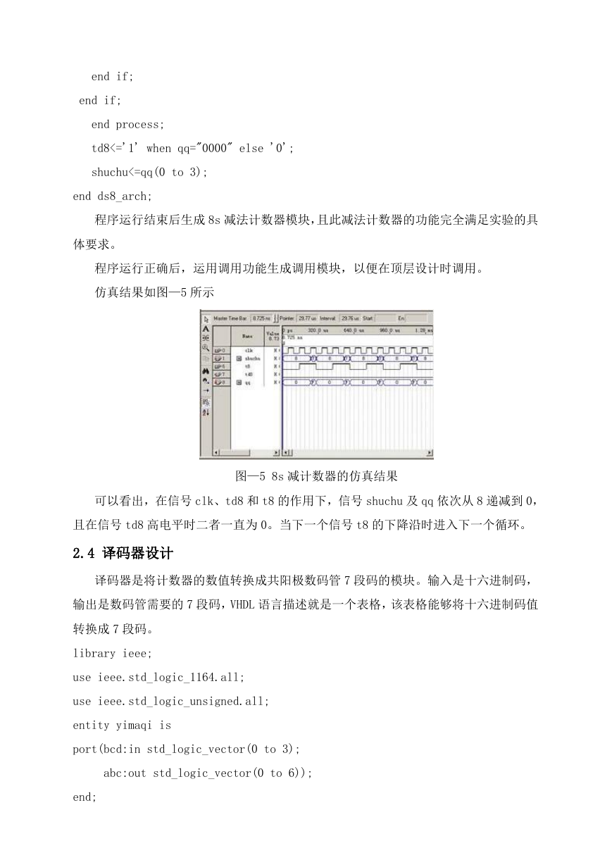
仿真结果如图—5 所示
图—5 8s 减计数器的仿真结果
可以看出,在信号 clk、td8 和 t8 的作用下,信号 shuchu 及 qq 依次从 8 递减到 0,
且在信号 td8 高电平时二者一直为 0。当下一个信号 t8 的下降沿时进入下一个循环。
2.4 译码器设计
译码器是将计数器的数值转换成共阳极数码管 7 段码的模块。输入是十六进制码,
输出是数码管需要的 7 段码,VHDL 语言描述就是一个表格,该表格能够将十六进制码值
转换成 7 段码。
library ieee;
use ieee.std_logic_1164.all;
use ieee.std_logic_unsigned.all;
entity yimaqi is
port(bcd:in std_logic_vector(0 to 3);
abc:out std_logic_vector(0 to 6));
end;
�
architecture yima_arch of yimaqi is
signal bb:std_logic_vector(0 to 6);
begin
process(bcd)
begin
case bcd is
when "0000"=>bb<="0000001";
when "0001"=>bb<="1001111";
when "0010"=>bb<="0010010";
when "0011"=>bb<="0000110";
when "0100"=>bb<="1001100";
when "0101"=>bb<="0100100";
when "0110"=>bb<="0100000";
when "0111"=>bb<="0001111";
when "1000"=>bb<="0000000";
when "1001"=>bb<="0000100";
when "1010"=>bb<="0001000";
when "1011"=>bb<="1100000";
when "1100"=>bb<="0110001";
when "1101"=>bb<="1000010";
when "1110"=>bb<="0110000";
when "1111"=>bb<="0111000";
when others=>bb<="1111111";
end case;
end process;
abc<=bb;
end yima_arch;
程序运行结束后生成译码器模块,且此译码器的功能完全满足实验的具体要求。
程序运行正确后,运用调用功能生成调用模块,以便在顶层设计时调用。
仿真结果如图—6 所示
�


 2023年江西萍乡中考道德与法治真题及答案.doc
 2012年重庆南川中考生物真题及答案.doc
 2013年江西师范大学地理学综合及文艺理论基础考研真题.doc
 2020年四川甘孜小升初语文真题及答案I卷.doc
 2020年注册岩土工程师专业基础考试真题及答案.doc
 2023-2024学年福建省厦门市九年级上学期数学月考试题及答案.doc
 2021-2022学年辽宁省沈阳市大东区九年级上学期语文期末试题及答案.doc
 2022-2023学年北京东城区初三第一学期物理期末试卷及答案.doc
 2018上半年江西教师资格初中地理学科知识与教学能力真题及答案.doc
 2012年河北国家公务员申论考试真题及答案-省级.doc
 2020-2021学年江苏省扬州市江都区邵樊片九年级上学期数学第一次质量检测试题及答案.doc
 2022下半年黑龙江教师资格证中学综合素质真题及答案.doc