ADSemiconductor®
TSM12S (12-CH Auto Sensitivity Calibration Capacitive Touch Sensor)
TSM12S
12-CH Auto Sensitivity Calibration Capacitive Touch Sensor
SPECIFICATION
VER. 1.0
Feb. 2018 ADSemiconductor Confidential
�
ADSemiconductor®
TSM12S (12-CH Auto Sensitivity Calibration Capacitive Touch Sensor)
Revision History
Rev.
1.0
First Creation
Description of change
Date
Originator
18.02.28
CH LEE
AD Semiconductor Confidential 2 / 32
�
ADSemiconductor®
TSM12S (12-CH Auto Sensitivity Calibration Capacitive Touch Sensor)
General
The TSM12S is 12-Channel capacitive sensor with
auto sensitivity calibration. And the supply voltage
range is from 1.8 to 5.0V.
The TSM12S has the SLEEP mode to save the
consumption. And the current consumption is 8 uA.
The TSM12S offers fast touch detection with fast
response operation.
The result of touch sensing can be checked by the I2C
serial interface. And touch intensity can be detectable
within 3 steps (Low, Middle and High).
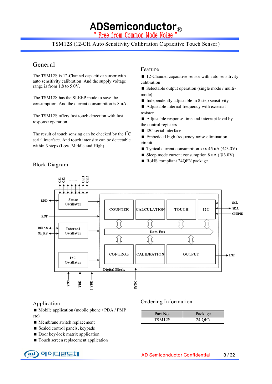
Block Diagram
Feature
12-Channel capacitive sensor with auto sensitivity
calibration
Selectable output operation (single mode / multi-
mode)
Independently adjustable in 8 step sensitivity
Adjustable internal frequency with external
resister
Adjustable response time and interrupt level by
the control registers
I2C serial interface
Embedded high frequency noise elimination
circuit
Typical current consumption xxx 45 uA (@3.0V)
Sleep mode current consumption 8 uA (@3.0V)
RoHS compliant 24QFN package
Application
Mobile application (mobile phone / PDA / PMP
etc)
Membrane switch replacement
Sealed control panels, keypads
Door key-lock matrix application
Touch screen replacement application
Ordering Information
Part No.
TSM12S
Package
24 QFN
AD Semiconductor Confidential 3 / 32
�
ADSemiconductor®
TSM12S (12-CH Auto Sensitivity Calibration Capacitive Touch Sensor)
Content
2.1
8.1
8.2
7
4.1
4.2
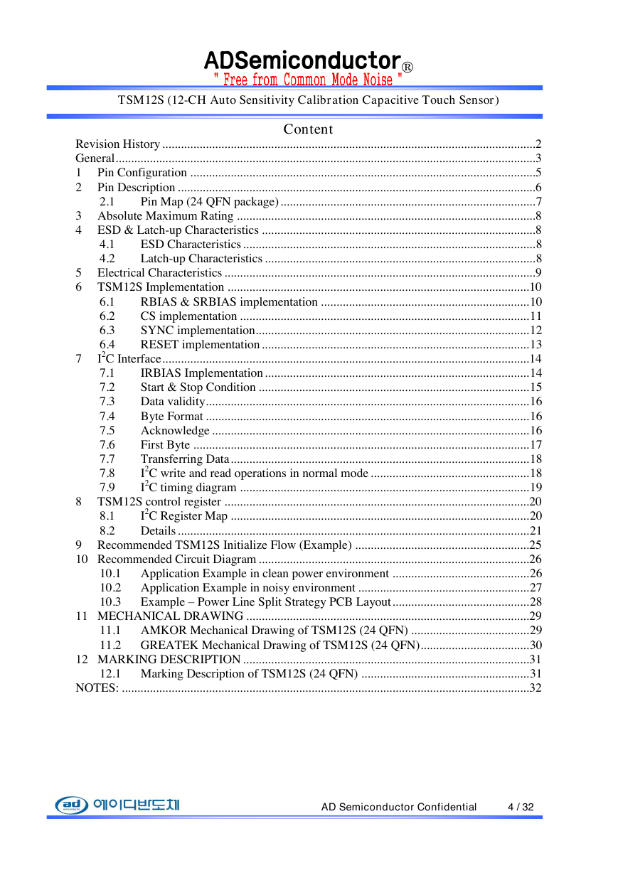
Revision History ........................................................................................................................ 2
General ....................................................................................................................................... 3
1 Pin Configuration ............................................................................................................... 5
2 Pin Description ................................................................................................................... 6
Pin Map (24 QFN package) .................................................................................. 7
3 Absolute Maximum Rating ................................................................................................ 8
4 ESD & Latch-up Characteristics ........................................................................................ 8
ESD Characteristics .............................................................................................. 8
Latch-up Characteristics ....................................................................................... 8
5 Electrical Characteristics .................................................................................................... 9
6 TSM12S Implementation ................................................................................................. 10
6.1
RBIAS & SRBIAS implementation ................................................................... 10
6.2
CS implementation ............................................................................................. 11
6.3
SYNC implementation........................................................................................ 12
6.4
RESET implementation ...................................................................................... 13
I2C Interface ...................................................................................................................... 14
IRBIAS Implementation ..................................................................................... 14
7.1
7.2
Start & Stop Condition ....................................................................................... 15
Data validity........................................................................................................ 16
7.3
Byte Format ........................................................................................................ 16
7.4
Acknowledge ...................................................................................................... 16
7.5
7.6
First Byte ............................................................................................................ 17
Transferring Data ................................................................................................ 18
7.7
I2C write and read operations in normal mode ................................................... 18
7.8
I2C timing diagram ............................................................................................. 19
7.9
8 TSM12S control register .................................................................................................. 20
I2C Register Map ................................................................................................ 20
Details ................................................................................................................. 21
9 Recommended TSM12S Initialize Flow (Example) ........................................................ 25
10 Recommended Circuit Diagram ....................................................................................... 26
10.1 Application Example in clean power environment ............................................ 26
10.2 Application Example in noisy environment ....................................................... 27
10.3
Example – Power Line Split Strategy PCB Layout ............................................ 28
11 MECHANICAL DRAWING ........................................................................................... 29
11.1 AMKOR Mechanical Drawing of TSM12S (24 QFN) ...................................... 29
11.2 GREATEK Mechanical Drawing of TSM12S (24 QFN)................................... 30
12 MARKING DESCRIPTION ............................................................................................ 31
12.1 Marking Description of TSM12S (24 QFN) ...................................................... 31
NOTES: ................................................................................................................................... 32
AD Semiconductor Confidential 4 / 32
�
ADSemiconductor®
TSM12S (12-CH Auto Sensitivity Calibration Capacitive Touch Sensor)
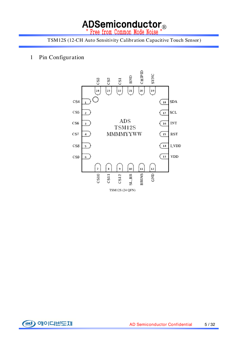
1 Pin Configuration
TSM12S (24 QFN)
AD Semiconductor Confidential 5 / 32
�
ADSemiconductor®
TSM12S (12-CH Auto Sensitivity Calibration Capacitive Touch Sensor)
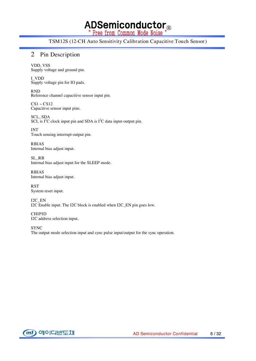
2 Pin Description
VDD, VSS
Supply voltage and ground pin.
I_VDD
Supply voltage pin for IO pads.
RND
Reference channel capacitive sensor input pin.
CS1 ~ CS12
Capacitive sensor input pins.
SCL, SDA
SCL is I2C clock input pin and SDA is I2C data input-output pin.
INT
Touch sensing interrupt output pin.
RBIAS
Internal bias adjust input.
SL_RB
Internal bias adjust input for the SLEEP mode.
RBIAS
Internal bias adjust input.
RST
System reset input.
I2C_EN
I2C Enable input. The I2C block is enabled when I2C_EN pin goes low.
CHIPID
I2C address selection input.
SYNC
The output mode selection input and sync pulse input/output for the sync operation.
AD Semiconductor Confidential 6 / 32
�
ADSemiconductor®
TSM12S (12-CH Auto Sensitivity Calibration Capacitive Touch Sensor)
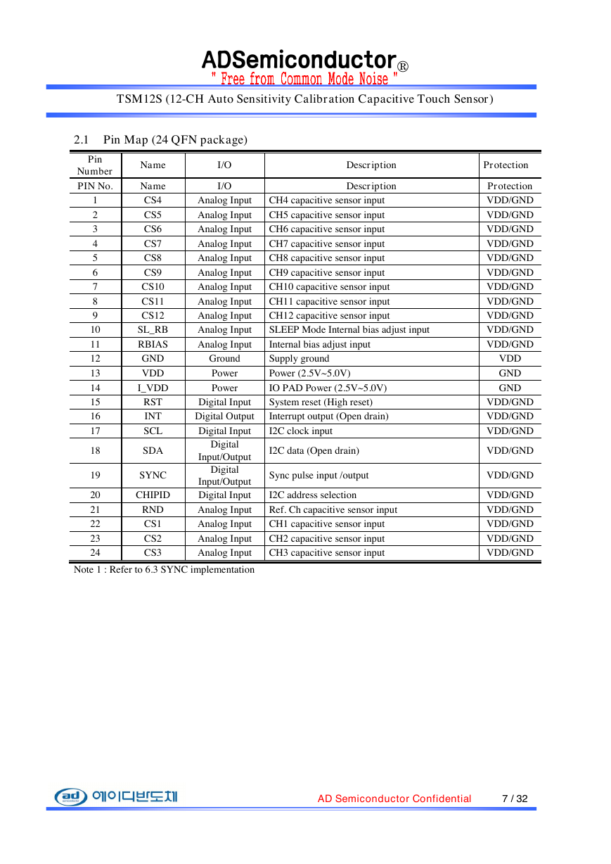
2.1 Pin Map (24 QFN package)
Pin
Number
PIN No.
1
2
3
4
5
6
7
8
9
10
11
12
13
14
15
16
17
18
19
20
21
22
23
24
Name
Name
CS4
CS5
CS6
CS7
CS8
CS9
CS10
CS11
CS12
SL_RB
RBIAS
GND
VDD
I_VDD
RST
INT
SCL
SDA
SYNC
CHIPID
RND
CS1
CS2
CS3
I/O
I/O
Description
Description
Analog Input
CH4 capacitive sensor input
Analog Input
CH5 capacitive sensor input
Analog Input
CH6 capacitive sensor input
Analog Input
CH7 capacitive sensor input
Analog Input
CH8 capacitive sensor input
Analog Input
CH9 capacitive sensor input
Analog Input
CH10 capacitive sensor input
Analog Input
CH11 capacitive sensor input
Analog Input
CH12 capacitive sensor input
Analog Input
SLEEP Mode Internal bias adjust input
Analog Input
Internal bias adjust input
Ground
Supply ground
Power
Power
Power (2.5V~5.0V)
IO PAD Power (2.5V~5.0V)
Digital Input
System reset (High reset)
Digital Output
Interrupt output (Open drain)
Digital Input
I2C clock input
Digital
Input/Output
Digital
Input/Output
Digital Input
I2C data (Open drain)
Sync pulse input /output
I2C address selection
Analog Input
Ref. Ch capacitive sensor input
Analog Input
CH1 capacitive sensor input
Analog Input
CH2 capacitive sensor input
Analog Input
CH3 capacitive sensor input
Note 1 : Refer to 6.3 SYNC implementation
Protection
Protection
VDD/GND
VDD/GND
VDD/GND
VDD/GND
VDD/GND
VDD/GND
VDD/GND
VDD/GND
VDD/GND
VDD/GND
VDD/GND
VDD
GND
GND
VDD/GND
VDD/GND
VDD/GND
VDD/GND
VDD/GND
VDD/GND
VDD/GND
VDD/GND
VDD/GND
VDD/GND
AD Semiconductor Confidential 7 / 32
�
ADSemiconductor®
TSM12S (12-CH Auto Sensitivity Calibration Capacitive Touch Sensor)
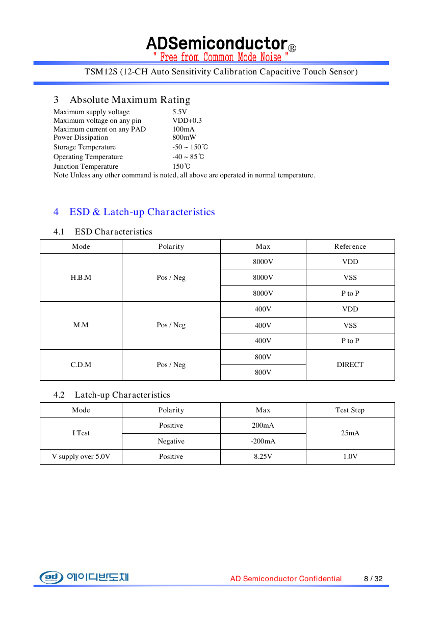
3 Absolute Maximum Rating
5.5V
Maximum supply voltage
VDD+0.3
Maximum voltage on any pin
100mA
Maximum current on any PAD
Power Dissipation
800mW
-50 ~ 150℃
Storage Temperature
-40 ~ 85℃
Operating Temperature
150℃
Junction Temperature
Note Unless any other command is noted, all above are operated in normal temperature.
4 ESD & Latch-up Characteristics
4.1 ESD Characteristics
Mode
Polarity
H.B.M
Pos / Neg
M.M
Pos / Neg
C.D.M
Pos / Neg
4.2 Latch-up Characteristics
Mode
I Test
V supply over 5.0V
Polarity
Positive
Negative
Positive
Max
8000V
8000V
8000V
400V
400V
400V
800V
800V
Max
200mA
-200mA
8.25V
Reference
VDD
VSS
P to P
VDD
VSS
P to P
DIRECT
Test Step
25mA
1.0V
AD Semiconductor Confidential 8 / 32
�


 2023年江西萍乡中考道德与法治真题及答案.doc
 2012年重庆南川中考生物真题及答案.doc
 2013年江西师范大学地理学综合及文艺理论基础考研真题.doc
 2020年四川甘孜小升初语文真题及答案I卷.doc
 2020年注册岩土工程师专业基础考试真题及答案.doc
 2023-2024学年福建省厦门市九年级上学期数学月考试题及答案.doc
 2021-2022学年辽宁省沈阳市大东区九年级上学期语文期末试题及答案.doc
 2022-2023学年北京东城区初三第一学期物理期末试卷及答案.doc
 2018上半年江西教师资格初中地理学科知识与教学能力真题及答案.doc
 2012年河北国家公务员申论考试真题及答案-省级.doc
 2020-2021学年江苏省扬州市江都区邵樊片九年级上学期数学第一次质量检测试题及答案.doc
 2022下半年黑龙江教师资格证中学综合素质真题及答案.doc