85DR2-TC / 85DR-TC
Chapter 2 Hardware Setup
To Get Things Ready for Hardware Setup !!!
1. We recommend to install your CPU before any other componentes. For
detailed installation instructions of processor, you can also refer to the
pamphlet enclosed in your CPU package.
2. Installing a cooling fan with a good heatsink is a must for proper heat
dissipation for your CPU. Get ready an appropriate fan with heatsink for
proper installation. Improper fan and installation will damage your CPU.
3. In case CPU Vcore, CPU clock or Frequency Ratio is adjustable onboard,
please follow the instructions described in the User manual for proper
setup. Incorrect setting will cause damage to your CPU.
The following topics are included in this chapter:
2-1 Pentium 4 CPU and Installation
2-2 Pentium 4 CPU Fan Installation
2-3 Memory Installation
2-4 AGP 4X (Accelerated Graphics Port) Installation
2-5 HDD Installation
2-6 FDD Installation
2-7 ATX Power Supply Installation
2-8 Jumper and Switch Settings
2-9 Other Connectors Configuration
16
�
Chapter 2 Hardware Setup
2-1 Pentium 4 CPU and Installation
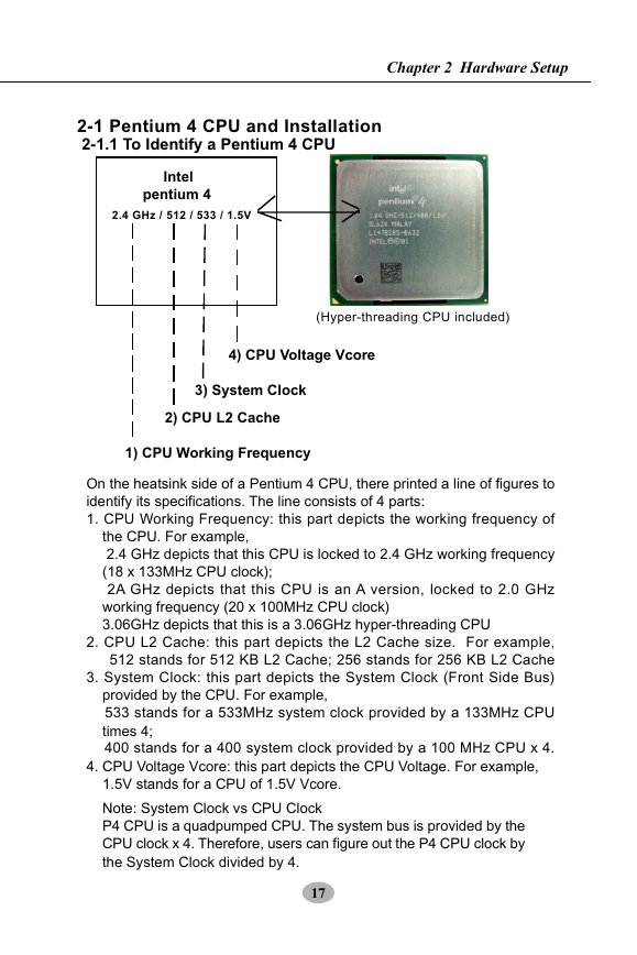
2-1.1 To Identify a Pentium 4 CPU
Intel
pentium 4
2.4 GHz / 512 / 533 / 1.5V
(Hyper-threading CPU included)
4) CPU Voltage Vcore
3) System Clock
2) CPU L2 Cache
1) CPU Working Frequency
On the heatsink side of a Pentium 4 CPU, there printed a line of figures to
identify its specifications. The line consists of 4 parts:
1. CPU Working Frequency: this part depicts the working frequency of
the CPU. For example,
2.4 GHz depicts that this CPU is locked to 2.4 GHz working frequency
(18 x 133MHz CPU clock);
2A GHz depicts that this CPU is an A version, locked to 2.0 GHz
working frequency (20 x 100MHz CPU clock)
3.06GHz depicts that this is a 3.06GHz hyper-threading CPU
2. CPU L2 Cache: this part depicts the L2 Cache size. For example,
512 stands for 512 KB L2 Cache; 256 stands for 256 KB L2 Cache
3. System Clock: this part depicts the System Clock (Front Side Bus)
provided by the CPU. For example,
533 stands for a 533MHz system clock provided by a 133MHz CPU
times 4;
400 stands for a 400 system clock provided by a 100 MHz CPU x 4.
4. CPU Voltage Vcore: this part depicts the CPU Voltage. For example,
1.5V stands for a CPU of 1.5V Vcore.
Note: System Clock vs CPU Clock
P4 CPU is a quadpumped CPU. The system bus is provided by the
CPU clock x 4. Therefore, users can figure out the P4 CPU clock by
the System Clock divided by 4.
17
�
85DR2-TC / 85DR-TC
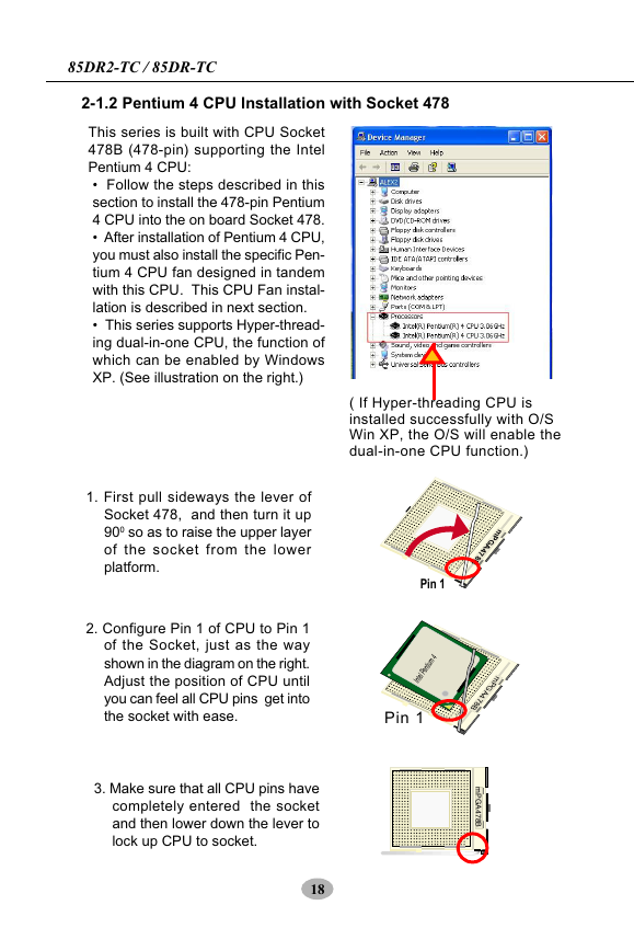
2-1.2 Pentium 4 CPU Installation with Socket 478
This series is built with CPU Socket
478B (478-pin) supporting the Intel
Pentium 4 CPU:
• Follow the steps described in this
section to install the 478-pin Pentium
4 CPU into the on board Socket 478.
• After installation of Pentium 4 CPU,
you must also install the specific Pen-
tium 4 CPU fan designed in tandem
with this CPU. This CPU Fan instal-
lation is described in next section.
• This series supports Hyper-thread-
ing dual-in-one CPU, the function of
which can be enabled by Windows
XP. (See illustration on the right.)
1. First pull sideways the lever of
Socket 478, and then turn it up
900 so as to raise the upper layer
of the socket from the lower
platform.
2. Configure Pin 1 of CPU to Pin 1
of the Socket, just as the way
shown in the diagram on the right.
Adjust the position of CPU until
you can feel all CPU pins get into
the socket with ease.
3. Make sure that all CPU pins have
completely entered the socket
and then lower down the lever to
lock up CPU to socket.
18
( If Hyper-threading CPU is
installed successfully with O/S
Win XP, the O/S will enable the
dual-in-one CPU function.)
Pin 1
Intel Pentium 4
Pin 1
m
P
G
A
4
7
8
B
m
P
G
A
4
7
8
B
m
P
G
A
4
7
8
B
�
Chapter 2 Hardware Setup
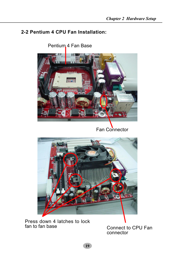
2-2 Pentium 4 CPU Fan Installation:
Pentium 4 Fan Base
Fan Connector
Press down 4 latches to lock
fan to fan base
Connect to CPU Fan
connector
19
�
85DR2-TC / 85DR-TC
2-3 Memory Installation
How to tackle the memory modules:
• Make sure to unplug your power supply before adding or removing
memory module. Failure to do so may cause severe damage to both your
mainboard and the memory module.
• Pay attention to the orientation of the DIMM slots. Forcing a DIMM into a
slot improperly will damage the memory module and the slot itself.
• Make sure you have the right type of memory module for your mainboard.
2-3.1 To Install DIMM Module
• This series only supports up to 2GB unbuffered DDR 266/200MHz
SDRAM, with 2 DDR DIMM slots on board. Do not insert other type of
memory module into these slots.
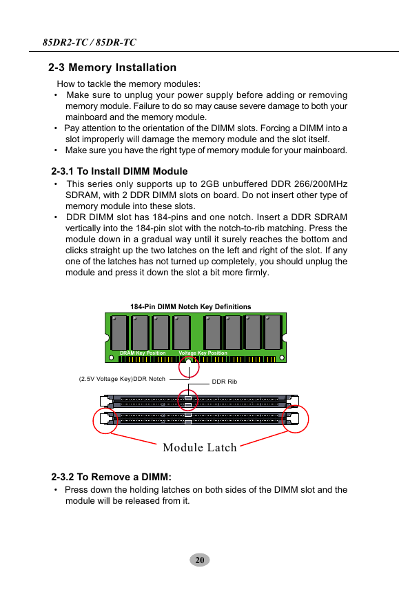
• DDR DIMM slot has 184-pins and one notch. Insert a DDR SDRAM
vertically into the 184-pin slot with the notch-to-rib matching. Press the
module down in a gradual way until it surely reaches the bottom and
clicks straight up the two latches on the left and right of the slot. If any
one of the latches has not turned up completely, you should unplug the
module and press it down the slot a bit more firmly.
184-Pin DIMM Notch Key Definitions
DRAM Key Position
Voltage Key Position
(2.5V Voltage Key)DDR Notch
DDR Rib
Module Latch
2-3.2 To Remove a DIMM:
• Press down the holding latches on both sides of the DIMM slot and the
module will be released from it.
20
�
Chapter 2 Hardware Setup
2-4 Install AGP4X with LED & Jumper Safeguard
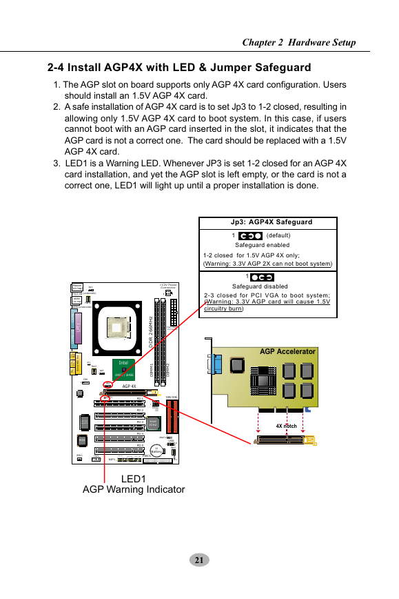
1. The AGP slot on board supports only AGP 4X card configuration. Users
should install an 1.5V AGP 4X card.
2. A safe installation of AGP 4X card is to set Jp3 to 1-2 closed, resulting in
allowing only 1.5V AGP 4X card to boot system. In this case, if users
cannot boot with an AGP card inserted in the slot, it indicates that the
AGP card is not a correct one. The card should be replaced with a 1.5V
AGP 4X card.
3. LED1 is a Warning LED. Whenever JP3 is set 1-2 closed for an AGP 4X
card installation, and yet the AGP slot is left empty, or the card is not a
correct one, LED1 will light up until a proper installation is done.
Jp3:
AGP4X Safeguard
1
(default)
Safeguard enabled
1-2 closed for 1.5V AGP 4X only;
(Warning: 3.3V AGP 2X can not boot system)
1
Safeguard disabled
2-3 closed for PCI VGA to boot system;
(Warning: 3.3V AGP card will cause 1.5V
circuitry burn)
AGP Accelerator
+12V Power
Connector
1
3
Main Power
Connector
2
M
M
I
D
IDE2
IDE1
z
H
M
6
6
2
R
D
D
1
M
M
I
D
1
4
P
J
5
P
J
1
P
G
A
J
2
P
G
A
J
Intel
ICH2
4X notch
Mouse
(on top)
Jp1
1
PS/2 KB
(underside)
USB0
(on top)
Fan1
USB1(underside)
1
T
P
L
1
M
O
C
2
M
O
C
e
n
i
t
u
O
L
e
n
t
r
o
P
I
D
I
M
/
e
m
a
c G
M
n
I
L
i
i
RT1
Fan2
Jp2
1
CD8
1
AC'97
Codec
ALC202A
LPC I/O
W83627HF
BIOS
m
P
G
A
4
7
8
B
1
Intel
Intel RG82845
i845D / i845E
AGP 4X
Jp3
1
LED1
PCI 1
PCI 2
PCI 3
PCI 4
PCI 5
1
1
1
JBAT1
Li
Battery
USB2
10
1
Fan3
RT2
WOL1
1
CN19
1
10
9
NJP1
1
IDE_LED
+
-
-
+
IRTX
IRRX
PWR
SMI
FDC1
Speaker
RST
+
-
PWR/LED
SUS_LED
1
LED1
AGP Warning Indicator
21
�
85DR2-TC / 85DR-TC
2-5 IDE Connector Installation
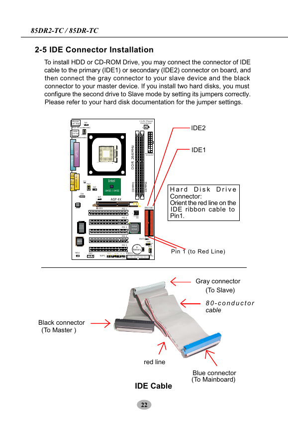
To install HDD or CD-ROM Drive, you may connect the connector of IDE
cable to the primary (IDE1) or secondary (IDE2) connector on board, and
then connect the gray connector to your slave device and the black
connector to your master device. If you install two hard disks, you must
configure the second drive to Slave mode by setting its jumpers correctly.
Please refer to your hard disk documentation for the jumper settings.
Mouse
(on top)
Jp1
1
PS/2 KB
(underside)
USB0
(on top)
Fan1
USB1(underside)
1
T
P
L
1
M
O
C
2
M
O
C
e
n
i
t
u
O
L
e
n
t
r
o
P
I
D
I
M
/
e
m
a
c G
M
n
I
L
i
i
RT1
Fan2
Jp2
1
CD8
1
AC'97
Codec
ALC202A
LPC I/O
W83627HF
BIOS
m
P
G
A
4
7
8
B
1
Intel
Intel RG82845
i845D / i845E
AGP 4X
Jp3
1
LED1
PCI 1
PCI 2
PCI 3
PCI 4
PCI 5
IDE_LED
+
-
-
+
IRTX
IRRX
PWR
SMI
FDC1
Speaker
RST
+
-
PWR/LED
SUS_LED
1
WOL1
1
CN19
1
10
9
NJP1
1
Black connector
(To Master )
+12V Power
Connector
1
3
Main Power
Connector
2
M
M
I
D
IDE2
IDE1
z
H
M
6
6
2
R
D
D
1
M
M
I
D
1
4
P
J
5
P
J
1
P
G
A
J
2
P
G
A
J
Intel
ICH2
IDE2
IDE1
H a r d D i s k D r i v e
Connector:
Orient the red line on the
IDE ribbon cable to
Pin1.
1
1
1
JBAT1
Li
Battery
USB2
10
1
Fan3
RT2
Pin 1 (to Red Line)
Gray connector
(To Slave)
8 0 - c o n d u c t o r
cable
red line
IDE Cable
22
Blue connector
(To Mainboard)
�
Chapter 2 Hardware Setup
2-6 FDC (Floppy Drive Connector) Installation
To install FDD (Floppy Disk Drive) to FDC, you should connect the end of
cable with single connector to the board, and connect the other end with
two plugs to the floppy drives.
Mouse
(on top)
Jp1
1
PS/2 KB
(underside)
USB0
(on top)
Fan1
USB1(underside)
1
T
P
L
1
M
O
C
2
M
O
C
e
n
i
t
u
O
L
e
n
t
r
o
P
I
D
I
M
/
e
m
a
c G
M
n
I
L
i
i
RT1
Fan2
Jp2
1
CD8
1
AC'97
Codec
ALC202A
LPC I/O
W83627HF
BIOS
m
P
G
A
4
7
8
B
1
Intel
Intel RG82845
i845D / i845E
AGP 4X
Jp3
1
LED1
PCI 1
PCI 2
PCI 3
PCI 4
PCI 5
+12V Power
Connector
1
3
Main Power
Connector
2
M
M
I
D
IDE2
IDE1
z
H
M
6
6
2
R
D
D
1
M
M
I
D
1
Floppy Drive Connector:
Orient the red line on the
floppy ribbon cable to Pin1.
4
P
J
5
P
J
1
P
G
A
J
2
P
G
A
J
Intel
ICH2
1
1
1
JBAT1
Li
Battery
USB2
10
1
Fan3
RT2
WOL1
1
CN19
1
10
9
NJP1
1
IDE_LED
+
-
-
+
IRTX
IRRX
PWR
SMI
FDC1
Speaker
RST
+
-
PWR/LED
SUS_LED
1
Pin 1 (to Red Line)
Signal Swap End
To 2nd Floppy Drive
red line
To mainboard
To 1st Floppy Drive
FDD Cable
23
�



 2023年江西萍乡中考道德与法治真题及答案.doc
 2012年重庆南川中考生物真题及答案.doc
 2013年江西师范大学地理学综合及文艺理论基础考研真题.doc
 2020年四川甘孜小升初语文真题及答案I卷.doc
 2020年注册岩土工程师专业基础考试真题及答案.doc
 2023-2024学年福建省厦门市九年级上学期数学月考试题及答案.doc
 2021-2022学年辽宁省沈阳市大东区九年级上学期语文期末试题及答案.doc
 2022-2023学年北京东城区初三第一学期物理期末试卷及答案.doc
 2018上半年江西教师资格初中地理学科知识与教学能力真题及答案.doc
 2012年河北国家公务员申论考试真题及答案-省级.doc
 2020-2021学年江苏省扬州市江都区邵樊片九年级上学期数学第一次质量检测试题及答案.doc
 2022下半年黑龙江教师资格证中学综合素质真题及答案.doc