logo资料库

OTM8019A data sheet.pdf

第1页 / 共298页
第2页 / 共298页
第3页 / 共298页
第4页 / 共298页
第5页 / 共298页
第6页 / 共298页
第7页 / 共298页
第8页 / 共298页
资料共298页,剩余部分请下载后查看
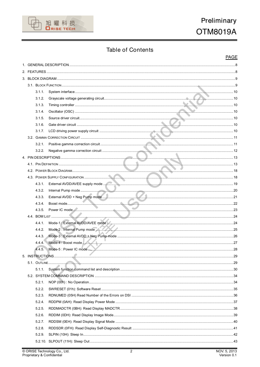
1. GENERAL DESCRIPTION
2. FEATURES
3. BLOCK DIAGRAM
3.1. Block Function
3.2.Gamma Correction Circuit
4. PIN DESCRIPTIONS
4.1. Pin Definition
4.2. Power Block Diagram
4.3. Power Supply Configuration
4.4. BOM List
4.4.1. Mode-1 : External AVDD/AVEE mode
4.4.2. Mode-2 : Internal Pump mode
4.4.3. Mode-3 : External AVDD + Neg Pump mode
4.4.4. Mode-4 : Boost mode
4.4.5. Mode-5 : Power ICmode
5. INSTRUCTIONS
5.1. Outline
5.2. SYSTEM COMMAND DESCRIPTION
5.2.1. NOP (00h) : No Operation
5.2.2. SWRESET (01h): Software Reset
5.2.3. RDNUMED (05H) Read Number of the Errors on DSI
5.2.4. RDDPM (0AH): Read Display Power Mode
5.2.5. RDDMADCTR (0BH): Read Display MADCTR
5.2.6. RDDIM (0DH): Read Display Image Mode
5.2.7. RDDSM (0EH): Read Display Signal Mode
5.2.8. RDDSDR (0FH): Read Display Self-Diagnostic Result
5.2.9. SLPIN (10H): Sleep In
5.2.10. SLPOUT (11H): Sleep Out
5.2.11. NORON (13H): Normal Display Mode On
5.2.12. INVOFF (20h) : Display Inversion Off
5.2.13. INVON (21h) : Display Inversion On
5.2.14. ALLPOFF (22H): All Pixels Off
5.2.15. ALLPON (23H): All Pixels On
5.2.16. DISPOFF (28H): Display Off
5.2.17. DISPON (29H): Display On
5.2.18. TEOFF (34H): Tearing Effect Line OFF
5.2.19. TEON (35H): Tearing Effect Line ON
5.2.20. WRDISBV (51H) Write Display Brightness
5.2.21. RDDISBV (52H) Read Display Brightness Value
5.2.22. WRCTRLD (53H) Write CTRL Display
5.2.23. RDCTRLD (54H) Read CTRL Display
5.2.24. WRCABC (55H) Write Content Adaptive Brightness Control
5.2.25. RDCABC (56H) Read Content Adaptive Brightness Control
5.2.26. WRCABCMB (5EH) Write CABC Minimum Brightness
5.2.27. RDCABCMB (5FH) Read CABC Minimum Brightness
5.2.28. RDPWMSDR (68H) Read Automatic Brightness Control Self-diagnostics Result
5.2.29. RDBWLB (70H) Read Back/White Low Bits
5.2.30. RDBkx (71H) Read Bkx
5.2.31. RDBky (72H) Read Bky
5.2.32. RDWx (73H) Read Wx
5.2.33. RDWy (74H) Read Wy
5.2.34. RDRGLB (75H) Read Red/Green Low Bits
5.2.35. RDRx (76H) Read Rx
5.2.36. RDRy (77H) Read Ry
5.2.37. RDGx (78H) Read Gx
5.2.38. RDGy (79H) Read Gy
5.2.39. RDBALB (7AH) Read Blue/AColour Low Bits
5.2.40. RDBx (7BH) Read Bx
5.2.41. RDDBy (7CH) Read By
5.2.42. RDAx (7DH) Read Ax
5.2.43. RDAy (7EH) Read Ay
5.2.44. RDDDBSTR (A1H): Read DDB Start
5.2.45. RDDDBCNT (A8H): Read DDB Continue
5.2.46. RDFCS (AAH): Read First Checksum
5.2.47. RDCCS (AFH): Read Continue Checksum
5.2.48. RDID1 (DAH): Read ID1
5.2.49. RDID2 (DBH): Read ID2
5.2.50. RDID3 (DCH): Read ID3
5.3. Customer Command List and Description (Manufacturer Command Set / Command 2)
5.3.1. ADRSFT (0000h): Address Shift Function
5.3.2. CMD2_ENA1 (FF00h): Enable Access Command 2 & Software EXTC Enable
5.3.3. CMD2_ENA2 (FF80h): Enable Access Orise Command 2
5.3.4. OTPSEL (A000h): OTP select region
5.3.5. MIPISET1 (B080h~ B08Ch): MIPI Setting 1
5.3.6. MIPISET2 (B0A1h): MIPI Setting 2
5.3.7. IF_PARA1 (B280H) IF Parameter 1
5.3.8. IF_PARA2 (B282H) IF Parameter 2
5.3.9. PAD_PARA1 (B390H) IOPAD Parameter 1
5.3.10. PAD_PARA2 (B391H) IOPAD Parameter 2
5.3.11. PAD_PARA3 (B392H) IOPAD Parameter 3
5.3.12. PANEL_TYPE (B3A1h): Panel Type Set
5.3.13. PDOTSET(B3A6h) Pseudo-Dot Inversion Driving Setting
5.3.14. PANEL_ENA_SET (B3A7h): Panel Enable Set
5.3.15. TSP1(C080h) TCON Setting Parameter 1
5.3.16. MCLK_SHIFT (C090h ~C095h): Mclk Shift Set
5.3.17. PTSP3 (C0A2~C0A4h) Panel Timing Setting Parameter 3
5.3.18. P_DRV_M(C0B4h) : Panel Driving Mode
5.3.19. OSC_ADJ(C181h) : Oscillator Adjustment for Normal Mode
5.3.20. OSC_REF_CTRL (C1A0h~C1A8h): Oscillator Reference Control
5.3.21. SD_PCH_CTRL(C480h): Source Driver Precharge Control
5.3.22. SD_CTRL_STATE (C487h~C489h): Source Driver Control State
5.3.23. POWER_DC2DC (C4A0h ~ C4ADh): Power Control for DC2DC Circuit
5.3.24. PWR_CTRL1(C580h): Power Control Setting 1
5.3.25. PWR_CTRL2(C590h): Power Control Setting 2 for Normal Mode
5.3.26. PWR_CTRL3(C5B0h): Power Control Setting 3 for DC Voltage Settings
5.3.27. PWM_PARA1 (C680H) PWM Parameter 1
5.3.28. PWM_PARA2 (C6B0H) PWM Parameter 2
5.3.29. PWM_PARA3 (C6B1H) PWM Parameter 3
5.3.30. PWM_PARA4 (C6B3H) PWM Parameter 4
5.3.31. PWM_PARA5 (C6B4H) PWM Parameter 5
5.3.32. CABCSET1 (C700h): CABC Setting
5.3.33. CABCSET2 (C800h): CABC gamma curve setting
5.3.34. AIESET(C900h): AIE Setting
5.3.35. CABCTH (CA80h): CABC threshold parameter setting
5.3.36. PANCTRLSET1 (CB80h~CB83h, CB85h~CB88h) Panel Control Setting 1
5.3.37. PANCTRLSET2 (CB90h~CB9Eh) Panel Control Setting 2
5.3.38. PANCTRLSET3 (CBA0h, CBA5h~CBAEh) Panel Control Setting 3
5.3.39. PANCTRLSET4 (CBB0h~CBB5h) Panel Control Setting 4
5.3.40. PANCTRLSET5 (CBC0h~CBCEh) Panel Control Setting 5
5.3.41. PANCTRLSET6 (CBD0h, CBD5h~CBDEh) Panel Control Setting 6
5.3.42. PANCTRLSET7 (CBE0h~CBE5h) Panel Control Setting 7
5.3.43. PANCTRLSET8 (CBF0h~CBF3h, CBF5h~CBF8h) Panel Control Setting 8
5.3.44. PANU2D1(CC80h~CC89h) Panel U2D Setting 1
5.3.45. PANU2D2(CC90h~CC9Eh) Panel U2D Setting 2
5.3.46. PANU2D3(CCA0h~CCAEh) Panel U2D Setting 3
5.3.47. PAND2U1(CCB0h~CCB9h) Panel D2U Setting 1
5.3.48. PAND2U2(CCC0h~CCCEh) Panel D2U Setting 2
5.3.49. PAND2U3(CCD0h~CCDEh) Panel D2U Setting 3
5.3.50. GOAVST(CE80h~CE8Bh) GOA VST Setting
5.3.51. GOAVEND(CE90h~CE9Bh) GOA VEND Setting
5.3.52. GOAGPSET(CE9Ch) GOA Group Setting
5.3.53. GOACLKA1(CEA0h~CEA6h) GOA CLKA1 Setting
5.3.54. GOACLKA2(CEA7h~CEADh) GOA CLKA2 Setting
5.3.55. GOACLKA3(CEB0h~CEB6h) GOA CLKA3 Setting
5.3.56. GOACLKA4(CEB7h~CEBDh) GOA CLKA4 Setting
5.3.57. GOACLKB1(CEC0h~CEC6h) GOA CLKB1 Setting
5.3.58. GOACLKB2(CEC7h~CECDh) GOA CLKB2 Setting
5.3.59. GOACLKB3(CED0h~CED6h) GOA CLKB3 Setting
5.3.60. GOACLKB4(CED7h~CEDDh) GOA CLKB4 Setting
5.3.61. GOAECLK(CFC0h~CFC4h) GOA ECLK Setting
5.3.62. GOAOPT1(CFC6h) GOA Other Options 1
5.3.63. GOATGOPT(CFC7h~CFC9h) GOA Signal Toggle Option Setting
5.3.64. GOA_F_CTRL (CFD0h ): GOA signal Frame behavior setting
5.3.65. WRID1(D000h) ID1 Setting
5.3.66. WRID2(D100h) ID2/ID3 Setting
5.3.67. WRDDB(D200h) DDB Setting
5.3.68. EXTCCHK (D300h): EXTC Check
5.3.69. CEEN(D680h): CE Enable
5.3.70. AIEEN(D700h): AIE Enable
5.3.71. GVDDSET (D800h): GVDD/NGVDD
5.3.72. VCOMDC (D900h): VCOM voltage setting
5.3.73. GMCT22P (E100h): Gamma Correction Characteristics Setting (2.2 + )
5.3.74. GMCT22N (E200h): Gamma Correction Characteristics Setting (2.2 - )
5.3.75. NVMIN (EB00h): NV Memory Write Mode
5.3.76. DGAMR (EC00h): Digital Gamma Correction Characteristics Setting (Red):
5.3.77. DGAMG (ED00h): Digital Gamma Correction Characteristics Setting (Green):
5.3.78. DGAMB (EE00h): Digital Gamma Correction Characteristics Setting (Blue):
5.3.79. PWR_EN_CTRL1 (F580~F58Bh): Power Enable Control Setting 1
5.3.80. PWR_EN_CTRL2 (F590~F599h): Power Enable Control Setting 2
5.3.81. PWR_EN_CTRL3 (F5A0~F5A7h): Power Enable Control Setting 3
5.3.82. PWR_EN_CTRL4 (F5B0~F5BBh): Power Enable Control Setting 4
6. FUNCTION DESCRIPTIONS
6.1. Interface type selection
6.2. MIPI-DSI interface
6.2.1. General description
6.2.2. Interface level communication
6.2.3. DSI data lanes
6.2.4. Packet level communication
6.2.5. Customer-defined generic read data type format
6.3. RGB Interface
6.3.1. RGB interface color mapping Format
6.3.2. RGB timing parameter
6.3.3. RGB interface power on/off sequence
6.4. I2C-Bus Interface
6.4.1.Characteristics of I2C-bus
6.4.2. I2C-bus protocol
6.5. Serial interface (SPI)
6.5.1. SPI Write mode
6.5.2. SPI read mode
6.6. Sleep Out-Command And Self-Diagnostic Functions Of The Display Module
6.6.1. Register loading detection
6.6.2. Functionality detection
6.7. Power On/Off Sequence
6.7.1. Case 1 – RESX line is held high or unstable by host at power on
6.7.2. Case 1 – RESX line is held high or unstable by host at power on
6.7.3. Uncontrolled power off
6.8. Power Level Definition
6.8.1. Power level
6.8.2. Power flow chart
6.9. Checksum
6.10. Content Adaptive Brightness Control (CABC)
6.10.1. Backlight(BC) brightness control
6.11. Orise Image Enhancement
6.11.1. Color Enhancement Lite(CE_lite)
6.11.2. Saturation gain ratio
6.11.3. Aaptive Saturation Gain Control
6.11.4. Color Enhancement Lite Features
6.12. Adaptive Image Enhancement ( AIE )
6.12.1. Concept
6.12.2. AIE function flow
6.12.3. CABC gamma curve setting
6.12.4. AIE gamma curve setting
6.13. NVM Programming Procedure
6.13.1. NVM program flow chart
6.13.2. Programming sequence
7. ELECTRICAL SPECIFICATIONS
7.1. Absolute Maximum Ratings
7.2. DC characteristic
7.2.1. Basic DC characteristic
7.2.2. MIPI DC character
7.3. AC timing characteristics
7.3.1. TCON Oscillaotr characteristics
7.3.2. Reset timing characteristics
7.3.3. Serial interface characteristics (SPI)
7.3.4. I2C interface characteristics
7.3.5. RGB interface characteristics
7.3.6. MIPI-DSI characteristics
8. CHIP INFORMATION
8.1. PAD Assignment
8.2. PAD Dimension
8.3. Pad Location
8.4. Alignment Mark
9. DISCLAIMER
10. REVISION HISTORY
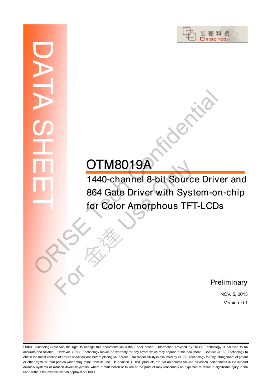
D A T A S H E E T OOTTMM88001199AA 11444400--cchhaannnneell 88--bbiitt SSoouurrccee DDrriivveerr aanndd 886644 GGaattee DDrriivveerr wwiitthh SSyysstteemm--oonn--cchhiipp ffoorr CCoolloorr AAmmoorrpphhoouuss TTFFTT--LLCCDDss PPrreelliimmiinnaarryy NOV. 5, 2013 Version 0.1 ORISE Technology reserves the right to change this documentation without prior notice. Information provided by ORISE Technology is believed to be accurate and reliable. However, ORISE Technology makes no warranty for any errors which may appear in this document. Contact ORISE Technology to obtain the latest version of device specifications before placing your order. No responsibility is assumed by ORISE Technology for any infringement of patent or other rights of third parties which may result from its use. In addition, ORISE products are not authorized for use as critical components in life support devices/ systems or aviation devices/systems, where a malfunction or failure of the product may reasonably be expected to result in significant injury to the user, without the express written approval of ORISE. ORISE Tech Confidential For 金達 Use Only
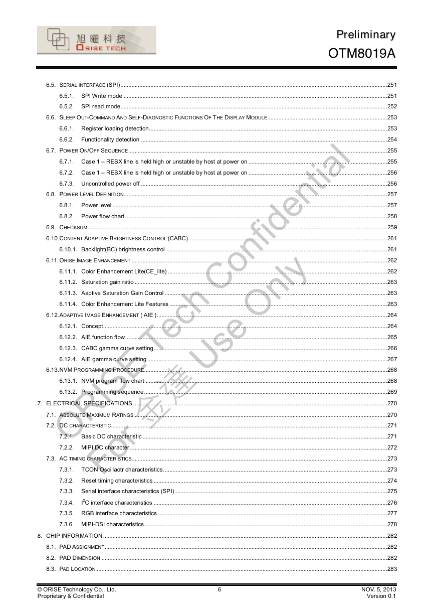
Table of Contents PPrreelliimmiinnaarryy OTM8019A PAGE 1. GENERAL DESCRIPTION................................................................................................................................................................................8 2. FEATURES........................................................................................................................................................................................................8 3. BLOCK DIAGRAM.............................................................................................................................................................................................9 3.1. BLOCK FUNCTION........................................................................................................................................................................................9 3.1.1. System interface........................................................................................................................................................................10 3.1.2. Grayscale voltage generating circuit.........................................................................................................................................10 3.1.3. Timing controller........................................................................................................................................................................10 3.1.4. Oscillator (OSC)........................................................................................................................................................................10 3.1.5. Source driver circuit...................................................................................................................................................................10 3.1.6. Gate driver circuit......................................................................................................................................................................10 3.1.7. LCD driving power supply circuit..............................................................................................................................................10 3.2. GAMMA CORRECTION CIRCUIT ..................................................................................................................................................................11 3.2.1. Positive gamma correction circuit.............................................................................................................................................11 3.2.2. Negative gamma correction circuit...........................................................................................................................................12 4. PIN DESCRIPTIONS.......................................................................................................................................................................................13 4.1. PIN DEFINITION .........................................................................................................................................................................................13 4.2. POWER BLOCK DIAGRAM...........................................................................................................................................................................18 4.3. POWER SUPPLY CONFIGURATION..............................................................................................................................................................18 4.3.1. External AVDD/AVEE supply mode..........................................................................................................................................19 4.3.2. Internal Pump mode..................................................................................................................................................................20 4.3.3. External AVDD + Neg Pump mode...........................................................................................................................................21 4.3.4. Boost mode................................................................................................................................................................................22 4.3.5. Power IC mode..........................................................................................................................................................................23 4.4. BOM LIST .................................................................................................................................................................................................24 4.4.1. Mode-1 : External AVDD/AVEE mode......................................................................................................................................24 4.4.2. Mode-2 : Internal Pump mode..................................................................................................................................................25 4.4.3. Mode-3 : External AVDD + Neg Pump mode...........................................................................................................................26 4.4.4. Mode-4 : Boost mode................................................................................................................................................................27 4.4.5. Mode-5 : Power IC mode..........................................................................................................................................................28 5. INSTRUCTIONS..............................................................................................................................................................................................29 5.1. OUTLINE....................................................................................................................................................................................................29 5.1.1. System function command list and description........................................................................................................................30 5.2. SYSTEM COMMAND DESCRIPTION...................................................................................................................................................34 5.2.1. NOP (00h) : No Operation.........................................................................................................................................................34 5.2.2. SWRESET (01h): Software Reset............................................................................................................................................35 5.2.3. RDNUMED (05H) Read Number of the Errors on DSI............................................................................................................36 5.2.4. RDDPM (0AH): Read Display Power Mode.............................................................................................................................37 5.2.5. RDDMADCTR (0BH): Read Display MADCTR........................................................................................................................38 5.2.6. RDDIM (0DH): Read Display Image Mode...............................................................................................................................39 5.2.7. RDDSM (0EH): Read Display Signal Mode.............................................................................................................................40 5.2.8. RDDSDR (0FH): Read Display Self-Diagnostic Result...........................................................................................................41 5.2.9. SLPIN (10H): Sleep In...............................................................................................................................................................42 5.2.10. SLPOUT (11H): Sleep Out........................................................................................................................................................43 © ORISE Technology Co., Ltd. Proprietary & Confidential 2 NOV. 5, 2013 Version 0.1 ORISE Tech Confidential For 金達 Use Only
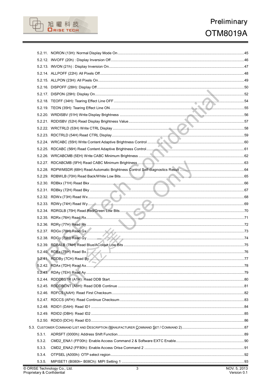
PPrreelliimmiinnaarryy OTM8019A 5.2.11. NORON (13H): Normal Display Mode On................................................................................................................................45 5.2.12. INVOFF (20h) : Display Inversion Off.......................................................................................................................................46 5.2.13. INVON (21h) : Display Inversion On.........................................................................................................................................47 5.2.14. ALLPOFF (22H): All Pixels Off..................................................................................................................................................48 5.2.15. ALLPON (23H): All Pixels On....................................................................................................................................................49 5.2.16. DISPOFF (28H): Display Off.....................................................................................................................................................50 5.2.17. DISPON (29H): Display On.......................................................................................................................................................52 5.2.18. TEOFF (34H): Tearing Effect Line OFF....................................................................................................................................54 5.2.19. TEON (35H): Tearing Effect Line ON........................................................................................................................................55 5.2.20. WRDISBV (51H) Write Display Brightness..............................................................................................................................56 5.2.21. RDDISBV (52H) Read Display Brightness Value.....................................................................................................................57 5.2.22. WRCTRLD (53H) Write CTRL Display.....................................................................................................................................58 5.2.23. RDCTRLD (54H) Read CTRL Display......................................................................................................................................59 5.2.24. WRCABC (55H) Write Content Adaptive Brightness Control..................................................................................................60 5.2.25. RDCABC (56H) Read Content Adaptive Brightness Control...................................................................................................61 5.2.26. WRCABCMB (5EH) Write CABC Minimum Brightness...........................................................................................................62 5.2.27. RDCABCMB (5FH) Read CABC Minimum Brightness............................................................................................................63 5.2.28. RDPWMSDR (68H) Read Automatic Brightness Control Self-diagnostics Result.................................................................64 5.2.29. RDBWLB (70H) Read Back/White Low Bits.............................................................................................................................65 5.2.30. RDBkx (71H) Read Bkx............................................................................................................................................................66 5.2.31. RDBky (72H) Read Bky............................................................................................................................................................67 5.2.32. RDWx (73H) Read Wx..............................................................................................................................................................68 5.2.33. RDWy (74H) Read Wy..............................................................................................................................................................69 5.2.34. RDRGLB (75H) Read Red/Green Low Bits..............................................................................................................................70 5.2.35. RDRx (76H) Read Rx................................................................................................................................................................71 5.2.36. RDRy (77H) Read Ry................................................................................................................................................................72 5.2.37. RDGx (78H) Read Gx...............................................................................................................................................................73 5.2.38. RDGy (79H) Read Gy...............................................................................................................................................................74 5.2.39. RDBALB (7AH) Read Blue/AColour Low Bits..........................................................................................................................75 5.2.40. RDBx (7BH) Read Bx................................................................................................................................................................76 5.2.41. RDDBy (7CH) Read By.............................................................................................................................................................77 5.2.42. RDAx (7DH) Read Ax................................................................................................................................................................78 5.2.43. RDAy (7EH) Read Ay................................................................................................................................................................79 5.2.44. RDDDBSTR (A1H): Read DDB Start........................................................................................................................................80 5.2.45. RDDDBCNT (A8H): Read DDB Continue................................................................................................................................81 5.2.46. RDFCS (AAH): Read First Checksum......................................................................................................................................82 5.2.47. RDCCS (AFH): Read Continue Checksum..............................................................................................................................83 5.2.48. RDID1 (DAH): Read ID1...........................................................................................................................................................84 5.2.49. RDID2 (DBH): Read ID2...........................................................................................................................................................85 5.2.50. RDID3 (DCH): Read ID3...........................................................................................................................................................86 5.3. CUSTOMER COMMAND LIST AND DESCRIPTION (MANUFACTURER COMMAND SET / COMMAND 2)...............................................................87 5.3.1. ADRSFT (0000h): Address Shift Function................................................................................................................................89 5.3.2. CMD2_ENA1 (FF00h): Enable Access Command 2 & Software EXTC Enable.....................................................................90 5.3.3. CMD2_ENA2 (FF80h): Enable Access Orise Command 2.....................................................................................................91 5.3.4. OTPSEL (A000h): OTP select region.......................................................................................................................................92 5.3.5. MIPISET1 (B080h~ B08Ch): MIPI Setting 1............................................................................................................................93 NOV. 5, 2013 Version 0.1 3 © ORISE Technology Co., Ltd. Proprietary & Confidential ORISE Tech Confidential For 金達 Use Only
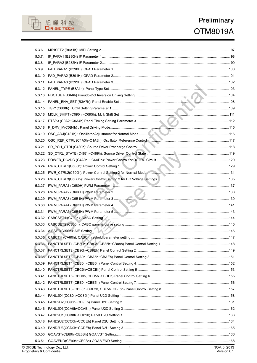
PPrreelliimmiinnaarryy OTM8019A 5.3.6. MIPISET2 (B0A1h): MIPI Setting 2...........................................................................................................................................97 5.3.7. IF_PARA1 (B280H) IF Parameter 1..........................................................................................................................................98 5.3.8. IF_PARA2 (B282H) IF Parameter 2..........................................................................................................................................99 5.3.9. PAD_PARA1 (B390H) IOPAD Parameter 1............................................................................................................................100 5.3.10. PAD_PARA2 (B391H) IOPAD Parameter 2............................................................................................................................101 5.3.11. PAD_PARA3 (B392H) IOPAD Parameter 3............................................................................................................................102 5.3.12. PANEL_TYPE (B3A1h): Panel Type Set................................................................................................................................103 5.3.13. PDOTSET(B3A6h) Pseudo-Dot Inversion Driving Setting.....................................................................................................104 5.3.14. PANEL_ENA_SET (B3A7h): Panel Enable Set.....................................................................................................................108 5.3.15. TSP1(C080h) TCON Setting Parameter 1.............................................................................................................................109 5.3.16. MCLK_SHIFT (C090h ~C095h): Mclk Shift Set.....................................................................................................................111 5.3.17. PTSP3 (C0A2~C0A4h) Panel Timing Setting Parameter 3...................................................................................................112 5.3.18. P_DRV_M(C0B4h) : Panel Driving Mode...............................................................................................................................115 5.3.19. OSC_ADJ(C181h) : Oscillator Adjustment for Normal Mode................................................................................................116 5.3.20. OSC_REF_CTRL (C1A0h~C1A8h): Oscillator Reference Control.......................................................................................117 5.3.21. SD_PCH_CTRL(C480h): Source Driver Precharge Control.................................................................................................118 5.3.22. SD_CTRL_STATE (C487h~C489h): Source Driver Control State........................................................................................119 5.3.23. POWER_DC2DC (C4A0h ~ C4ADh): Power Control for DC2DC Circuit.............................................................................120 5.3.24. PWR_CTRL1(C580h): Power Control Setting 1....................................................................................................................129 5.3.25. PWR_CTRL2(C590h): Power Control Setting 2 for Normal Mode........................................................................................131 5.3.26. PWR_CTRL3(C5B0h): Power Control Setting 3 for DC Voltage Settings.............................................................................135 5.3.27. PWM_PARA1 (C680H) PWM Parameter 1............................................................................................................................137 5.3.28. PWM_PARA2 (C6B0H) PWM Parameter 2...........................................................................................................................138 5.3.29. PWM_PARA3 (C6B1H) PWM Parameter 3...........................................................................................................................139 5.3.30. PWM_PARA4 (C6B3H) PWM Parameter 4...........................................................................................................................141 5.3.31. PWM_PARA5 (C6B4H) PWM Parameter 5...........................................................................................................................143 5.3.32. CABCSET1 (C700h): CABC Setting......................................................................................................................................144 5.3.33. CABCSET2 (C800h): CABC gamma curve setting................................................................................................................145 5.3.34. AIESET(C900h): AIE Setting..................................................................................................................................................146 5.3.35. CABCTH (CA80h): CABC threshold parameter setting.........................................................................................................147 5.3.36. PANCTRLSET1 (CB80h~CB83h, CB85h~CB88h) Panel Control Setting 1.........................................................................148 5.3.37. PANCTRLSET2 (CB90h~CB9Eh) Panel Control Setting 2...................................................................................................149 5.3.38. PANCTRLSET3 (CBA0h, CBA5h~CBAEh) Panel Control Setting 3.....................................................................................151 5.3.39. PANCTRLSET4 (CBB0h~CBB5h) Panel Control Setting 4...................................................................................................152 5.3.40. PANCTRLSET5 (CBC0h~CBCEh) Panel Control Setting 5..................................................................................................153 5.3.41. PANCTRLSET6 (CBD0h, CBD5h~CBDEh) Panel Control Setting 6....................................................................................155 5.3.42. PANCTRLSET7 (CBE0h~CBE5h) Panel Control Setting 7...................................................................................................156 5.3.43. PANCTRLSET8 (CBF0h~CBF3h, CBF5h~CBF8h) Panel Control Setting 8........................................................................157 5.3.44. PANU2D1(CC80h~CC89h) Panel U2D Setting 1..................................................................................................................158 5.3.45. PANU2D2(CC90h~CC9Eh) Panel U2D Setting 2..................................................................................................................161 5.3.46. PANU2D3(CCA0h~CCAEh) Panel U2D Setting 3.................................................................................................................162 5.3.47. PAND2U1(CCB0h~CCB9h) Panel D2U Setting 1.................................................................................................................163 5.3.48. PAND2U2(CCC0h~CCCEh) Panel D2U Setting 2.................................................................................................................164 5.3.49. PAND2U3(CCD0h~CCDEh) Panel D2U Setting 3.................................................................................................................165 5.3.50. GOAVST(CE80h~CE8Bh) GOA VST Setting.........................................................................................................................166 5.3.51. GOAVEND(CE90h~CE9Bh) GOA VEND Setting..................................................................................................................168 NOV. 5, 2013 Version 0.1 4 © ORISE Technology Co., Ltd. Proprietary & Confidential ORISE Tech Confidential For 金達 Use Only
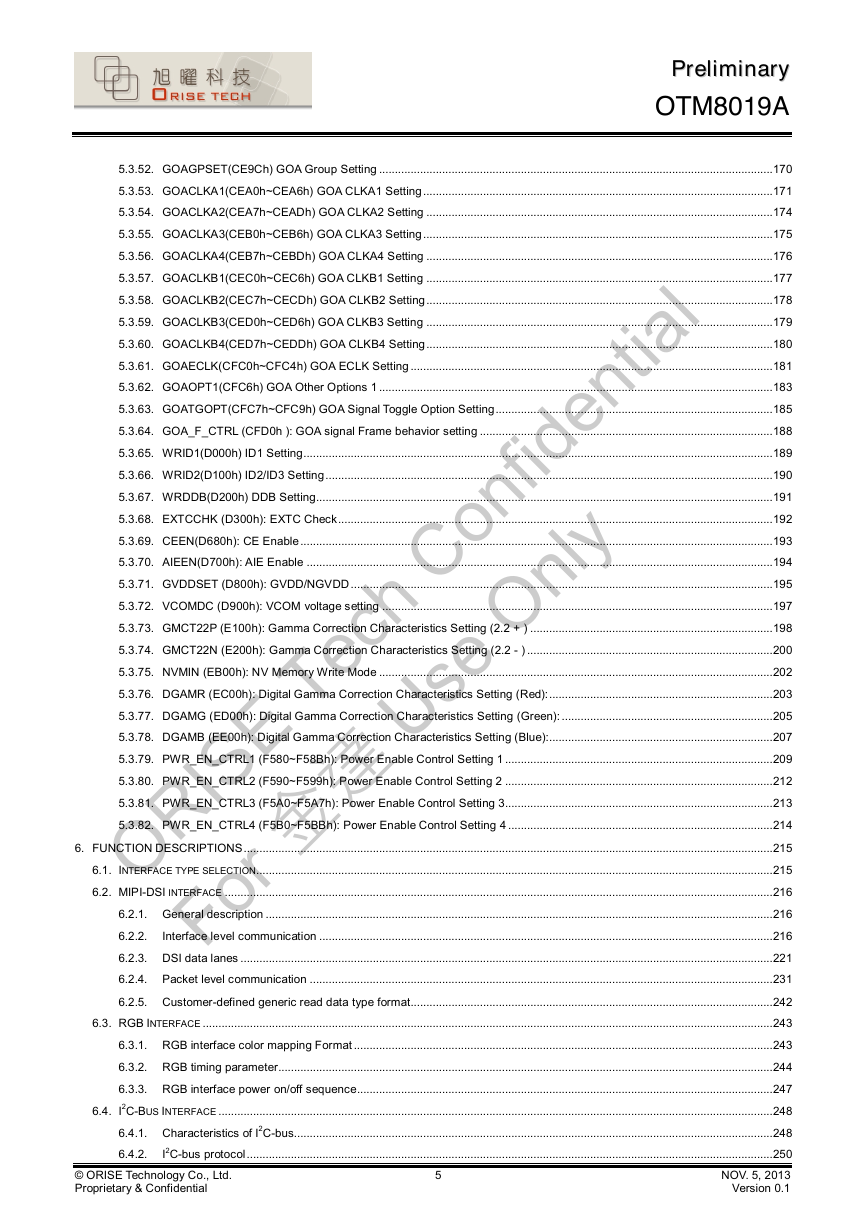
PPrreelliimmiinnaarryy OTM8019A 5.3.52. GOAGPSET(CE9Ch) GOA Group Setting.............................................................................................................................170 5.3.53. GOACLKA1(CEA0h~CEA6h) GOA CLKA1 Setting...............................................................................................................171 5.3.54. GOACLKA2(CEA7h~CEADh) GOA CLKA2 Setting..............................................................................................................174 5.3.55. GOACLKA3(CEB0h~CEB6h) GOA CLKA3 Setting...............................................................................................................175 5.3.56. GOACLKA4(CEB7h~CEBDh) GOA CLKA4 Setting..............................................................................................................176 5.3.57. GOACLKB1(CEC0h~CEC6h) GOA CLKB1 Setting..............................................................................................................177 5.3.58. GOACLKB2(CEC7h~CECDh) GOA CLKB2 Setting..............................................................................................................178 5.3.59. GOACLKB3(CED0h~CED6h) GOA CLKB3 Setting..............................................................................................................179 5.3.60. GOACLKB4(CED7h~CEDDh) GOA CLKB4 Setting..............................................................................................................180 5.3.61. GOAECLK(CFC0h~CFC4h) GOA ECLK Setting...................................................................................................................181 5.3.62. GOAOPT1(CFC6h) GOA Other Options 1.............................................................................................................................183 5.3.63. GOATGOPT(CFC7h~CFC9h) GOA Signal Toggle Option Setting........................................................................................185 5.3.64. GOA_F_CTRL (CFD0h ): GOA signal Frame behavior setting.............................................................................................188 5.3.65. WRID1(D000h) ID1 Setting.....................................................................................................................................................189 5.3.66. WRID2(D100h) ID2/ID3 Setting..............................................................................................................................................190 5.3.67. WRDDB(D200h) DDB Setting.................................................................................................................................................191 5.3.68. EXTCCHK (D300h): EXTC Check..........................................................................................................................................192 5.3.69. CEEN(D680h): CE Enable......................................................................................................................................................193 5.3.70. AIEEN(D700h): AIE Enable....................................................................................................................................................194 5.3.71. GVDDSET (D800h): GVDD/NGVDD......................................................................................................................................195 5.3.72. VCOMDC (D900h): VCOM voltage setting............................................................................................................................197 5.3.73. GMCT22P (E100h): Gamma Correction Characteristics Setting (2.2 + ).............................................................................198 5.3.74. GMCT22N (E200h): Gamma Correction Characteristics Setting (2.2 - )..............................................................................200 5.3.75. NVMIN (EB00h): NV Memory Write Mode.............................................................................................................................202 5.3.76. DGAMR (EC00h): Digital Gamma Correction Characteristics Setting (Red):.......................................................................203 5.3.77. DGAMG (ED00h): Digital Gamma Correction Characteristics Setting (Green):...................................................................205 5.3.78. DGAMB (EE00h): Digital Gamma Correction Characteristics Setting (Blue):.......................................................................207 5.3.79. PWR_EN_CTRL1 (F580~F58Bh): Power Enable Control Setting 1.....................................................................................209 5.3.80. PWR_EN_CTRL2 (F590~F599h): Power Enable Control Setting 2.....................................................................................212 5.3.81. PWR_EN_CTRL3 (F5A0~F5A7h): Power Enable Control Setting 3.....................................................................................213 5.3.82. PWR_EN_CTRL4 (F5B0~F5BBh): Power Enable Control Setting 4....................................................................................214 6. FUNCTION DESCRIPTIONS........................................................................................................................................................................215 6.1. INTERFACE TYPE SELECTION....................................................................................................................................................................215 6.2. MIPI-DSI INTERFACE ..............................................................................................................................................................................216 6.2.1. General description.................................................................................................................................................................216 6.2.2. Interface level communication................................................................................................................................................216 6.2.3. DSI data lanes.........................................................................................................................................................................221 6.2.4. Packet level communication...................................................................................................................................................231 6.2.5. Customer-defined generic read data type format...................................................................................................................242 6.3. RGB INTERFACE .....................................................................................................................................................................................243 6.3.1. RGB interface color mapping Format.....................................................................................................................................243 6.3.2. RGB timing parameter.............................................................................................................................................................244 6.3.3. RGB interface power on/off sequence....................................................................................................................................247 6.4. I2C-BUS INTERFACE ................................................................................................................................................................................248 6.4.1. Characteristics of I2C-bus........................................................................................................................................................248 I2C-bus protocol.......................................................................................................................................................................250 6.4.2. NOV. 5, 2013 Version 0.1 5 © ORISE Technology Co., Ltd. Proprietary & Confidential ORISE Tech Confidential For 金達 Use Only
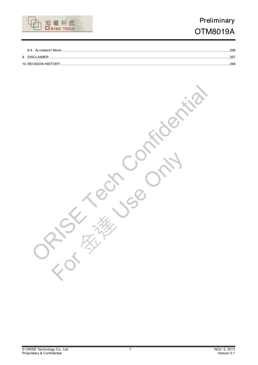
PPrreelliimmiinnaarryy OTM8019A 6.5. SERIAL INTERFACE (SPI).........................................................................................................................................................................251 6.5.1. SPI Write mode.......................................................................................................................................................................251 6.5.2. SPI read mode.........................................................................................................................................................................252 6.6. SLEEP OUT-COMMAND AND SELF-DIAGNOSTIC FUNCTIONS OF THE DISPLAY MODULE............................................................................253 6.6.1. Register loading detection.......................................................................................................................................................253 6.6.2. Functionality detection............................................................................................................................................................254 6.7. POWER ON/OFF SEQUENCE....................................................................................................................................................................255 6.7.1. Case 1 – RESX line is held high or unstable by host at power on........................................................................................255 6.7.2. Case 1 – RESX line is held high or unstable by host at power on........................................................................................256 6.7.3. Uncontrolled power off............................................................................................................................................................256 6.8. POWER LEVEL DEFINITION.......................................................................................................................................................................257 6.8.1. Power level..............................................................................................................................................................................257 6.8.2. Power flow chart......................................................................................................................................................................258 6.9. CHECKSUM..............................................................................................................................................................................................259 6.10. CONTENT ADAPTIVE BRIGHTNESS CONTROL (CABC)..............................................................................................................................261 6.10.1. Backlight(BC) brightness control............................................................................................................................................261 6.11. ORISE IMAGE ENHANCEMENT ..................................................................................................................................................................262 6.11.1. Color Enhancement Lite(CE_lite)...........................................................................................................................................262 6.11.2. Saturation gain ratio................................................................................................................................................................263 6.11.3. Aaptive Saturation Gain Control.............................................................................................................................................263 6.11.4. Color Enhancement Lite Features..........................................................................................................................................263 6.12. ADAPTIVE IMAGE ENHANCEMENT ( AIE )..................................................................................................................................................264 6.12.1. Concept....................................................................................................................................................................................264 6.12.2. AIE function flow......................................................................................................................................................................265 6.12.3. CABC gamma curve setting....................................................................................................................................................266 6.12.4. AIE gamma curve setting........................................................................................................................................................267 6.13. NVM PROGRAMMING PROCEDURE..........................................................................................................................................................268 6.13.1. NVM program flow chart.........................................................................................................................................................268 6.13.2. Programming sequence..........................................................................................................................................................269 7. ELECTRICAL SPECIFICATIONS.................................................................................................................................................................270 7.1. ABSOLUTE MAXIMUM RATINGS ................................................................................................................................................................270 7.2. DC CHARACTERISTIC...............................................................................................................................................................................271 7.2.1. Basic DC characteristic...........................................................................................................................................................271 7.2.2. MIPI DC character...................................................................................................................................................................272 7.3. AC TIMING CHARACTERISTICS..................................................................................................................................................................273 7.3.1. TCON Oscillaotr characteristics..............................................................................................................................................273 7.3.2. Reset timing characteristics....................................................................................................................................................274 7.3.3. Serial interface characteristics (SPI)......................................................................................................................................275 7.3.4. I2C interface characteristics....................................................................................................................................................276 7.3.5. RGB interface characteristics.................................................................................................................................................277 7.3.6. MIPI-DSI characteristics..........................................................................................................................................................278 8. CHIP INFORMATION....................................................................................................................................................................................282 8.1. PAD ASSIGNMENT...................................................................................................................................................................................282 8.2. PAD DIMENSION .....................................................................................................................................................................................282 8.3. PAD LOCATION ........................................................................................................................................................................................283 © ORISE Technology Co., Ltd. Proprietary & Confidential 6 NOV. 5, 2013 Version 0.1 ORISE Tech Confidential For 金達 Use Only
PPrreelliimmiinnaarryy OTM8019A 8.4. ALIGNMENT MARK ...................................................................................................................................................................................296 9. DISCLAIMER.................................................................................................................................................................................................297 10. REVISION HISTORY.....................................................................................................................................................................................298 © ORISE Technology Co., Ltd. Proprietary & Confidential 7 NOV. 5, 2013 Version 0.1 ORISE Tech Confidential For 金達 Use Only
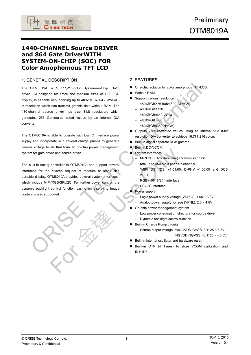
1440-CHANNEL Source DRIVER and 864 Gate DriverWITH SYSTEM-ON-CHIP (SOC) FOR Color Amophomous TFT LCD 1. GENERAL DESCRIPTION The OTM8019A, a 16,777,216-color System-on-Chip (SoC) driver LSI designed for small and medium sizes of TFT LCD display, is capable of supporting up to 480xRGBx864 ( WVGA ) in resolution which can transmit graphic data without RAM. The 480-channel source driver has true 8-bit resolution, which generates 256 Gamma-corrected values by an internal D/A converter. The OTM8019A is able to operate with low IO interface power supply and incorporate with several charge pumps to generate various voltage levels that form an on-chip power management system for gate driver and source driver. The built-in timing controller in OTM8019A can support several interfaces for the diverse request of medium or small size portable display. OTM8019A provides several system interfaces, which include MIPI/RGB/SPI/I2C. For further power control, the dynamic backlight control function basing on displaying image content is also supported. PPrreelliimmiinnaarryy OTM8019A 2. FEATURES n One-chip solution for color amorphous TFT-LCD. n Without RAM. n Support various resolution - 480XRGBX864(854,800)(WVGA) - 480XRGBX720 - 480XRGBx640(VGA) - 480XRGBx480 - 480XRGBx360(HVGA) n Outputs 256 γ-corrected values using an internal true 8-bit resolution D/A converter to achieve 16,777,216 colors n Built-in digital separate RGB gamma n Built-in DC-VCOM. n System interfaces - MIPI DSI ( 1/2/ data lane) ;transmission bit rate up to 550 Mb/s per data channel. *MIPI DSI (DSI v1.01.00, D-PHY v1.00.00 and DCS v1.01). - RGB ( 16/18/24 ) interface - SPI/I2C interface n Power supply - Logic power supply voltage (VDDIO): 1.65 ~ 3.3V - Analog power supply voltage (VPNL): 2.3 ~ 4.8V n On-chip power management system - Low power consumption structure for source driver. - Dynamic backlight control function. n Built-in Charge Pump circuits - Source output voltage level GVDD-GVSS: 3.1125 ~ 6.3V NGVDD-NGVSS: -3.1125 ~ --6.3V n Built-in internal oscillator and hardware reset. n Built –in OTP (4 Times) to store VCOM calibration and ID1~ID3. © ORISE Technology Co., Ltd. Proprietary & Confidential 8 NOV. 5, 2013 Version 0.1 ORISE Tech Confidential For 金達 Use Only
分享到:
收藏