Simplified Analysis and Design of Series-
resonant LLC Half-bridge Converters
resonant LLC Half-bridge Converters
MLD GROUP
INDUSTRIAL & POWER CONVERSION DIVISION
Off-line SMPS BU Application Lab
Claudio Adragna
Application & Architecture Manager, System & Application Expert
I&PC Div. - Off-line SMPS Appl. Lab
�
Presentation Outline
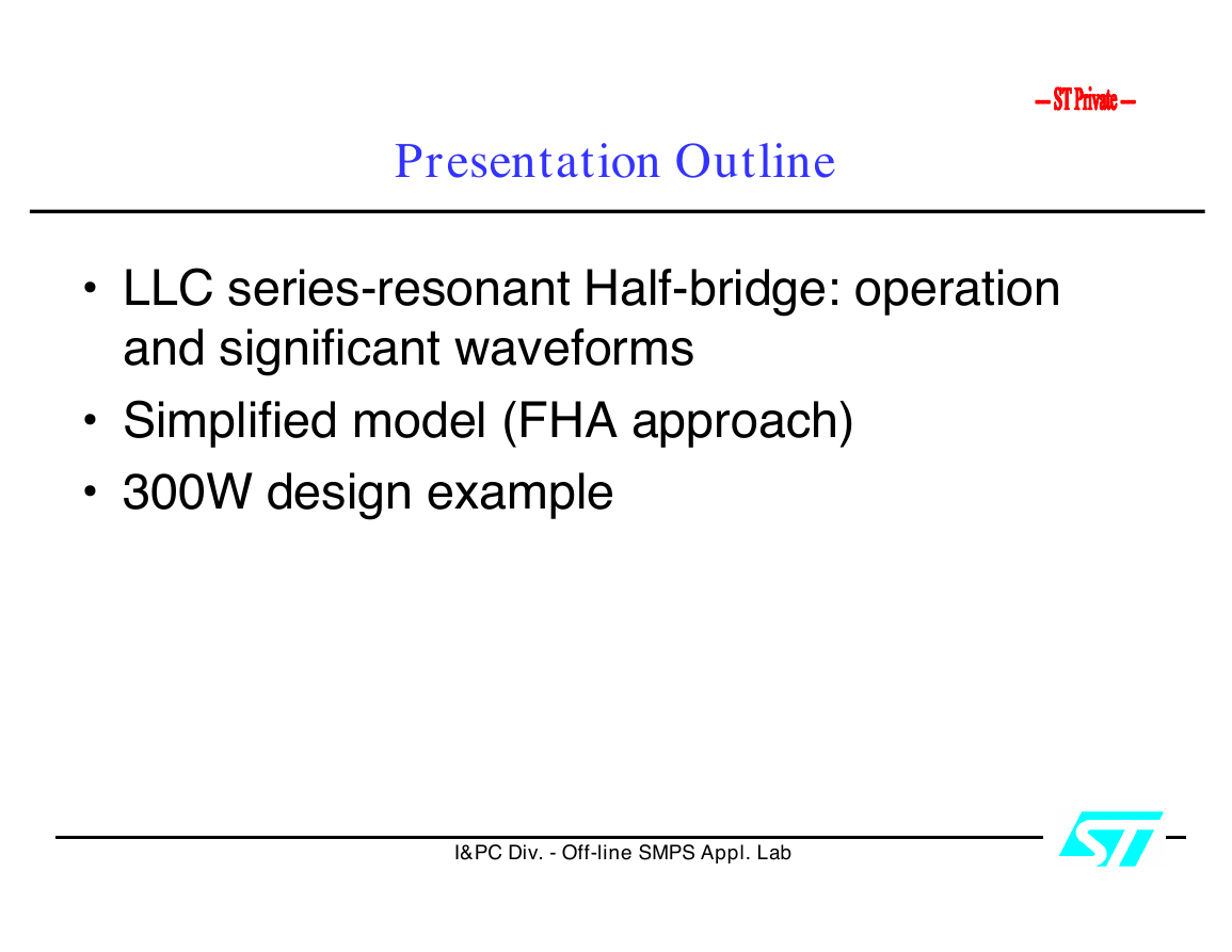
• LLC series-resonant Half-bridge: operation
and significant waveforms
• Simplified model (FHA approach)
• 300W design example
• 300W design example
I&PC Div. - Off-line SMPS Appl. Lab
�
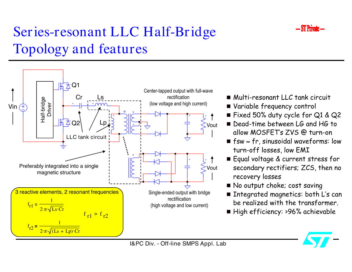
Series-resonant LLC Half-Bridge
Topology and features
Vin
e
g
d
i
r
b
-
f
l
a
H
r
e
v
i
r
D
Q1
Cr
Ls
Q2
Lp
LLC tank circuit
LLC tank circuit
Preferably integrated into a single
magnetic structure
3 reactive elements, 2 resonant frequencies
fr1
fr2
2 p
2 p
1
Ls Cr
1
Lp+
Ls
(
) Cr
>
f r1
f r2
Center-tapped output with full-wave
rectification
(low voltage and high current)
Vout
Vout
Single-ended output with bridge
rectifiication
(high voltage and low current)
� Multi-resonant LLC tank circuit
� Variable frequency control
� Fixed 50% duty cycle for Q1 & Q2
� Dead-time between LG and HG to
allow MOSFET’s ZVS @ turn-on
allow MOSFET’s ZVS @ turn-on
� fsw » fr, sinusoidal waveforms: low
turn-off losses, low EMI
� Equal voltage & current stress for
secondary rectifiers; ZCS, then no
recovery losses
� No output choke; cost saving
� Integrated magnetics: both L’s can
be realized with the transformer.
� High efficiency: >96% achievable
I&PC Div. - Off-line SMPS Appl. Lab
�
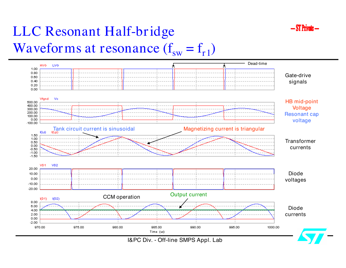
LLC Resonant Half-bridge
Waveforms at resonance (fsw = fr1)
Dead-time
Tank circuit current is sinusoidal
Magnetizing current is triangular
CCM operation
Output current
I&PC Div. - Off-line SMPS Appl. Lab
Gate-drive
signals
HB mid-point
Voltage
Resonant cap
voltage
Transformer
currents
Diode
voltages
Diode
currents
�
LLC Resonant Half-bridge
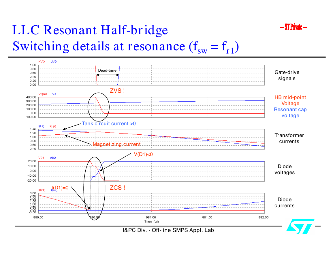
Switching details at resonance (fsw = fr1)
Dead-time
ZVS !
Tank circuit current >0
Magnetizing current
V(D1)<0
I(D1)=0
ZCS !
I&PC Div. - Off-line SMPS Appl. Lab
Gate-drive
signals
HB mid-point
Voltage
Resonant cap
voltage
Transformer
currents
Diode
voltages
Diode
currents
�
LLC Resonant Half-bridge
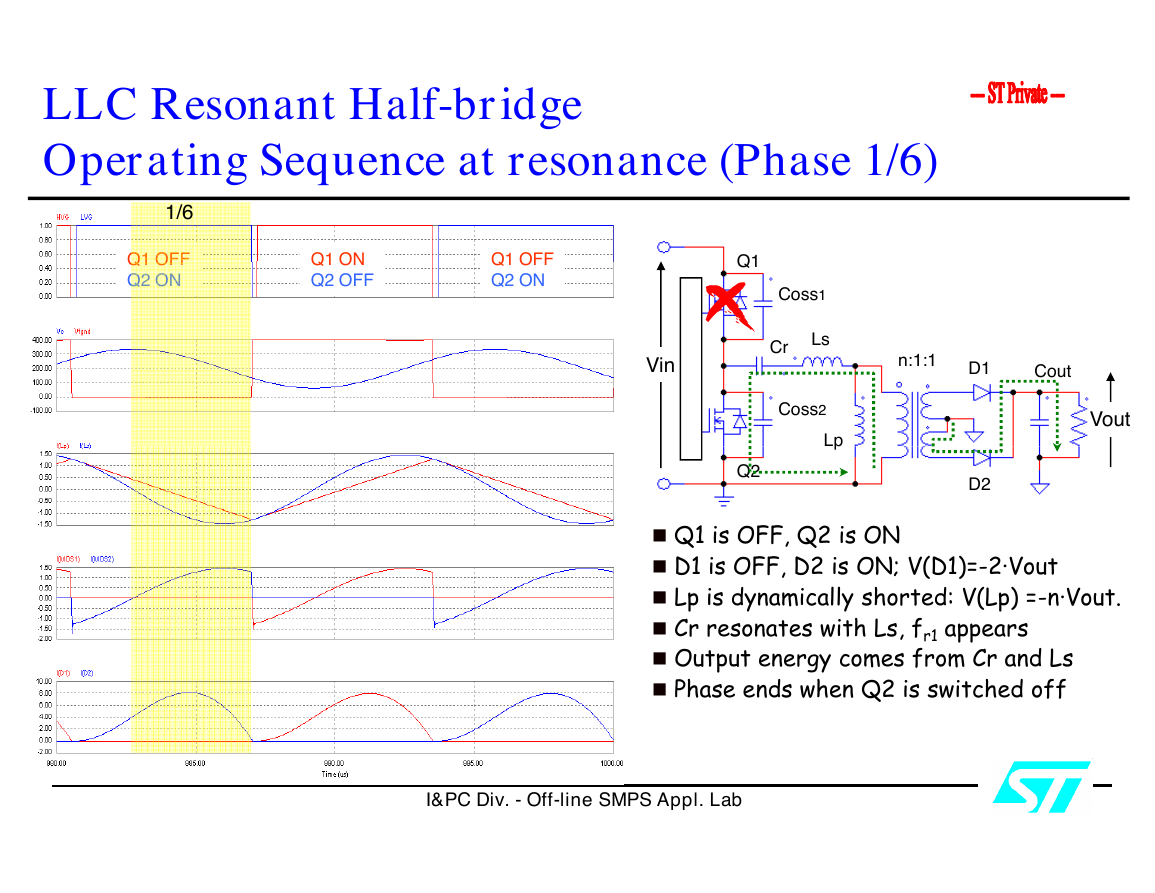
Operating Sequence at resonance (Phase 1/6)
1/6
Q1 OFF
Q2 ON
Q1 ON
Q2 OFF
Q1 OFF
Q2 ON
Vin
Q1
Q2
Coss1
Ls
Cr
Coss2
Lp
Lp
n:1:1
D1
Cout
Vout
D2
� Q1 is OFF, Q2 is ON
� D1 is OFF, D2 is ON; V(D1)=-2·Vout
� Lp is dynamically shorted: V(Lp) =-n·Vout.
� Cr resonates with Ls, fr1 appears
� Output energy comes from Cr and Ls
� Phase ends when Q2 is switched off
I&PC Div. - Off-line SMPS Appl. Lab
�
LLC Resonant Half-bridge
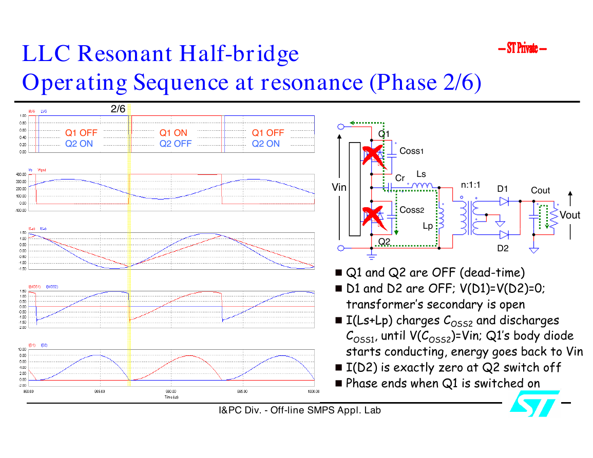
Operating Sequence at resonance (Phase 2/6)
2/6
Q1 OFF
Q2 ON
Q1 ON
Q2 OFF
Q1 OFF
Q2 ON
Vin
Q1
Q2
Coss1
Ls
Cr
Coss2
Lp
Lp
n:1:1
D1
Cout
Vout
D2
� Q1 and Q2 are OFF (dead-time)
� D1 and D2 are OFF; V(D1)=V(D2)=0;
transformer’s secondary is open
� I(Ls+Lp) charges COSS2 and discharges
COSS1, until V(COSS2)=Vin; Q1’s body diode
starts conducting, energy goes back to Vin
� I(D2) is exactly zero at Q2 switch off
� Phase ends when Q1 is switched on
I&PC Div. - Off-line SMPS Appl. Lab
�
LLC Resonant Half-bridge
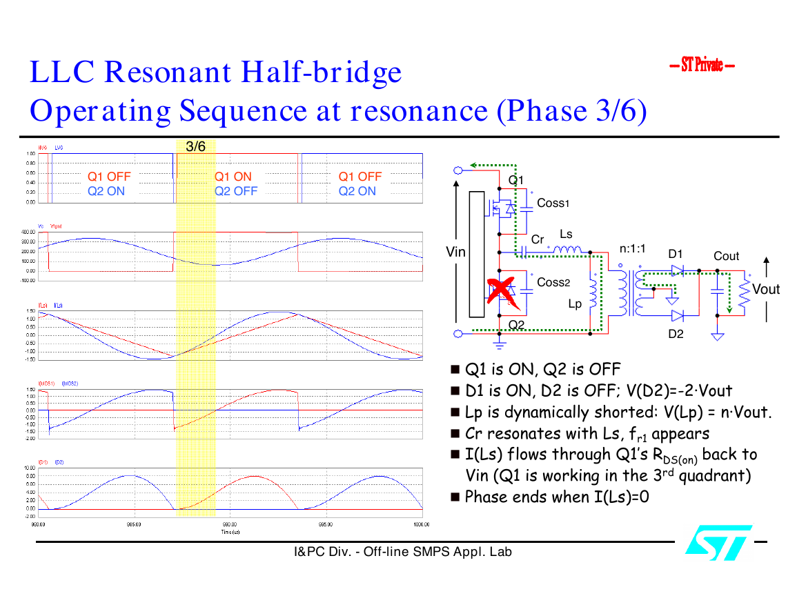
Operating Sequence at resonance (Phase 3/6)
3/6
Q1 OFF
Q2 ON
Q1 ON
Q2 OFF
Q1 OFF
Q2 ON
Vin
Q1
Q2
Coss1
Ls
Cr
Coss2
Lp
Lp
n:1:1
D1
Cout
Vout
D2
� Q1 is ON, Q2 is OFF
� D1 is ON, D2 is OFF; V(D2)=-2·Vout
� Lp is dynamically shorted: V(Lp) = n·Vout.
� Cr resonates with Ls, fr1 appears
� I(Ls) flows through Q1’s RDS(on) back to
Vin (Q1 is working in the 3rd quadrant)
� Phase ends when I(Ls)=0
I&PC Div. - Off-line SMPS Appl. Lab
�


 2023年江西萍乡中考道德与法治真题及答案.doc
 2012年重庆南川中考生物真题及答案.doc
 2013年江西师范大学地理学综合及文艺理论基础考研真题.doc
 2020年四川甘孜小升初语文真题及答案I卷.doc
 2020年注册岩土工程师专业基础考试真题及答案.doc
 2023-2024学年福建省厦门市九年级上学期数学月考试题及答案.doc
 2021-2022学年辽宁省沈阳市大东区九年级上学期语文期末试题及答案.doc
 2022-2023学年北京东城区初三第一学期物理期末试卷及答案.doc
 2018上半年江西教师资格初中地理学科知识与教学能力真题及答案.doc
 2012年河北国家公务员申论考试真题及答案-省级.doc
 2020-2021学年江苏省扬州市江都区邵樊片九年级上学期数学第一次质量检测试题及答案.doc
 2022下半年黑龙江教师资格证中学综合素质真题及答案.doc