logo资料库

PHY DP83848 中文文档.pdf

第1页 / 共91页
第2页 / 共91页
第3页 / 共91页
第4页 / 共91页
第5页 / 共91页
第6页 / 共91页
第7页 / 共91页
第8页 / 共91页
资料共91页,剩余部分请下载后查看
内容
1  介绍
1.1 特性
1.2 应用范围
1.3 支持国防、航天和医疗应用
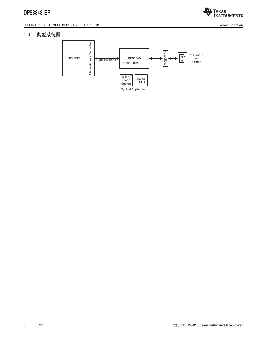
1.4 典型系统图
2 概述
2.1 描述
2.2 订购信息
2.3 器件信息
2.4 端子说明
3 ELECTRICAL SPECIFICATIONS
3.1 Absolute Maximum Ratings
3.2 Recommended Operating Conditions
3.3 Thermal Information
3.4 DC Specifications
3.4.1 Electrical Characteristics
3.5 AC Specifications
3.5.1 Power Up Timing
3.5.2 Reset Timing
3.5.3 MII Serial Management Timing
3.5.4 100 Mb/s MII Transmit Timing
3.5.5 100 Mb/s MII Receive Timing
3.5.6 100BASE-TX Transmit Packet Latency Timing
3.5.7 100BASE-TX Transmit Packet Deassertion Timing
3.5.8 100BASE-TX Transmit Timing (tR/F & Jitter)
3.5.9 100BASE-TX Receive Packet Latency Timing
3.5.10 100BASE-TX Receive Packet Deassertion Timing
3.5.11 10 Mb/s MII Transmit Timing
3.5.12 10 Mb/s MII Receive Timing
3.5.13 10 Mb/s Serial Mode Transmit Timing
3.5.14 10 Mb/s Serial Mode Receive Timing
3.5.15 10BASE-T Transmit Timing (Start of Packet)
3.5.16 10BASE-T Transmit Timing (End of Packet)
3.5.17 10BASE-T Receive Timing (Start of Packet)
3.5.18 10BASE-T Receive Timing (End of Packet)
3.5.19 10 Mb/s Heartbeat Timing
3.5.20 10 Mb/s Jabber Timing
3.5.21 10BASE-T Normal Link Pulse Timing
3.5.22 Auto-Negotiation Fast Link Pulse (FLP) Timing
3.5.23 100BASE-TX Signal Detect Timing
3.5.24 100 Mb/s Internal Loopback Timing
3.5.25 10 Mb/s Internal Loopback Timing
3.5.26 RMII Transmit Timing
3.5.27 RMII Receive Timing
3.5.28 Isolation Timing
3.5.29 25 MHz_OUT Timing
4 CONFIGURATION
4.1 Auto-Negotiation
4.1.1 Auto-Negotiation Pin Control
4.1.2 Auto-Negotiation Register Control
4.1.3 Auto-Negotiation Parallel Detection
4.1.4 Auto-Negotiation Restart
4.1.5 Enabling Auto-Negotiation via Software
4.1.6 Auto-Negotiation Complete Time
4.2 Auto-MDIX
4.3 PHY Address
4.3.1 MII Isolate Mode
4.4 LED Interface
4.4.1 LEDs
4.4.2 LED Direct Control
4.5 Half Duplex vs Full Duplex
4.6 Internal Loopback
4.7 BIST
5 FUNCTIONAL DESCRIPTION
5.1 MII Interface
5.1.1 Nibble-Wide MII Data Interface
5.1.2 Collision Detect
5.1.3 Carrier Sense
5.2 Reduced MII Interface
5.3 10 Mb Serial Network Interface (SNI)
5.4 802.3u MII Serial Management Interface
5.4.1 Serial Management Register Access
5.4.2 Serial Management Access Protocol
5.4.3 Serial Management Preamble Suppression
6 ARCHITECTURE
6.1 100BASE-TX Transmitter
6.1.1 Code-Group Encoding and Injection
6.1.2 Scrambler
6.1.3 NRZ to NRZI Encoder
6.1.4 Binary to MLT-3 Convertor
6.2 100BASE-TX Receiver
6.2.1 Analog Front End
6.2.2 Digital Signal Processor
6.2.2.1 Digital Adaptive Equalization and Gain Control
6.2.2.2 Base Line Wander Compensation
6.2.3 Signal Detect
6.2.4 MLT-3 to NRZI Decoder
6.2.5 NRZI to NRZ
6.2.6 Serial to Parallel
6.2.7 Descrambler
6.2.8 Code-Group Alignment
6.2.9 4B/5B Decoder
6.2.10 100BASE-TX Link Integrity Monitor
6.2.11 Bad SSD Detection
6.3 10BASE-T Transceiver Module
6.3.1 Operational Modes
6.3.1.1 Half Duplex Mode
6.3.1.2 Full Duplex Mode
6.3.2 Smart Squelch
6.3.3 Collision Detection and SQE
6.3.4 Carrier Sense
6.3.5 Normal Link Pulse Detection/Generation
6.3.6 Jabber Function
6.3.7 Automatic Link Polarity Detection and Correction
6.3.8 Transmit and Receive Filtering
6.3.9 Transmitter
6.3.10 Receiver
7 DESIGN GUIDELINES
7.1 TPI Network Circuit
7.2 ESD Protection
7.3 Clock In (X1) Requirements
7.3.1 Oscillator
7.3.2 Crystal
7.4 Power Feedback Circuit
7.5 Power Down and Interrupt
7.5.1 Power Down Control Mode
7.5.2 Interrupt Mechanisms
7.6 Energy Detect Mode
7.7 Thermal Vias Recommendation
8 RESET OPERATION
8.1 Hardware Reset
8.2 Software Reset
9 REGISTER BLOCK
9.1 
9.2 Register Definition
9.2.1 Basic Mode Control Register (BMCR)
9.2.2 Basic Mode Status Register (BMSR)
9.2.3 PHY Identifier Register #1 (PHYIDR1)
9.2.4 PHY Identifier Register #2 (PHYIDR2)
9.2.5 Auto-Negotiation Advertisement Register (ANAR)
9.2.6 Auto-Negotiation Link Partner Ability Register (ANLPAR) (BASE Page)
9.2.7 Auto-Negotiation Link Partner Ability Register (ANLPAR) (Next Page)
9.2.8 Auto-Negotiate Expansion Register (ANER)
9.2.9 Auto-Negotiation Next Page Transmit Register (ANNPTR)
9.3 Extended Registers
9.3.1 PHY Status Register (PHYSTS)
9.3.2 MII Interrupt Control Register (MICR)
9.3.3 MII Interrupt Status and Miscellaneous Control Register (MISR)
9.3.4 False Carrier Sense Counter Register (FCSCR)
9.3.5 Receiver Error Counter Register (RECR)
9.3.6 100 Mb/s PCS Configuration and Status Register (PCSR)
9.3.7 RMII and Bypass Register (RBR)
9.3.8 LED Direct Control Register (LEDCR)
9.3.9 PHY Control Register (PHYCR)
9.3.10 10Base-T Status/Control Register (10BTSCR)
9.3.11 CD Test and BIST Extensions Register (CDCTRL1)
9.3.12 Energy Detect Control (EDCR)
DP83848-EP PHYTER™ 军军用用温温度度单单端端口口 10/100 MB/S 以以太太网网物物理理层层收收发发器器 Data Manual PRODUCTION DATA information is current as of publication date. Products conform to specifications per the terms of the Texas Instruments standard warranty. Production processing does not necessarily include testing of all parameters. Literature Number: ZHCSAB9D September 2012–Revised June 2013
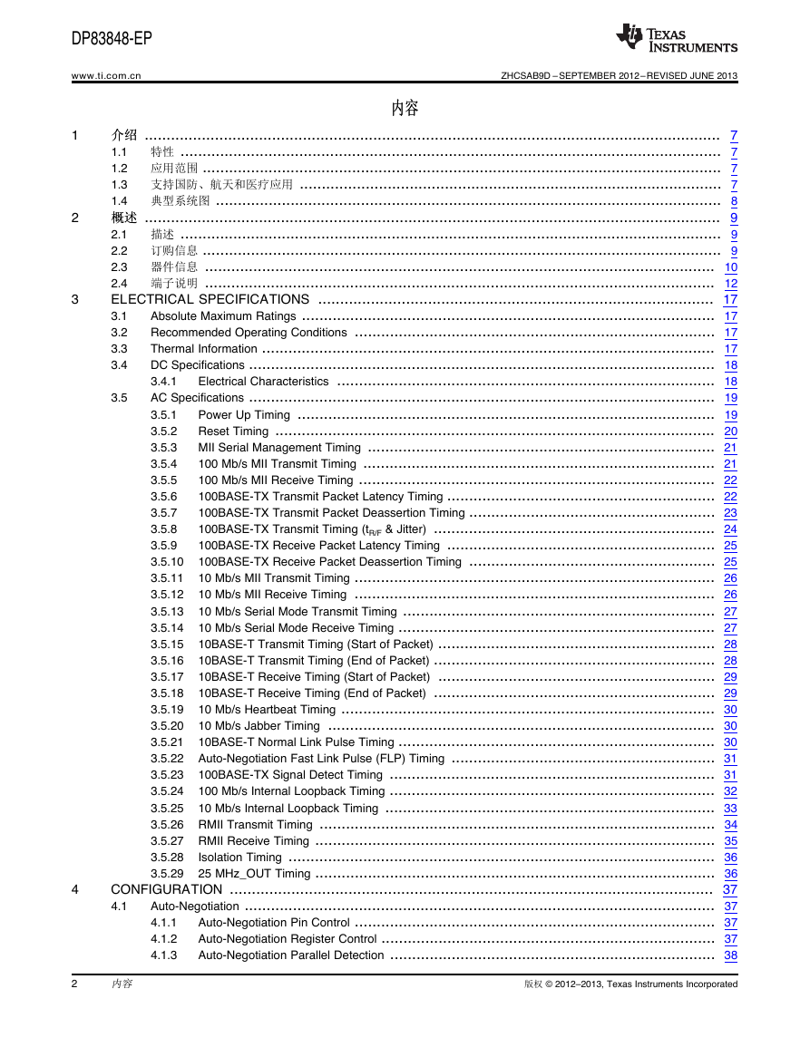
DP83848-EP www.ti.com.cn ZHCSAB9D –SEPTEMBER 2012–REVISED JUNE 2013 内内容容 1 2 3 4 3.5 介介绍绍 ................................................................................................................................... 7 1.1 特性 ........................................................................................................................... 7 1.2 应用范围 ...................................................................................................................... 7 1.3 支持国防、航天和医疗应用 ................................................................................................ 7 1.4 典型系统图 ................................................................................................................... 8 概概述述 ................................................................................................................................... 9 2.1 描述 ........................................................................................................................... 9 2.2 订购信息 ...................................................................................................................... 9 2.3 器件信息 .................................................................................................................... 10 2.4 端子说明 .................................................................................................................... 12 ELECTRICAL SPECIFICATIONS .......................................................................................... 17 Absolute Maximum Ratings .............................................................................................. 17 3.1 Recommended Operating Conditions .................................................................................. 17 3.2 Thermal Information ....................................................................................................... 17 3.3 DC Specifications .......................................................................................................... 18 3.4 Electrical Characteristics ...................................................................................... 18 3.4.1 AC Specifications .......................................................................................................... 19 Power Up Timing ............................................................................................... 19 3.5.1 Reset Timing .................................................................................................... 20 3.5.2 MII Serial Management Timing ............................................................................... 21 3.5.3 100 Mb/s MII Transmit Timing ................................................................................ 21 3.5.4 100 Mb/s MII Receive Timing ................................................................................. 22 3.5.5 100BASE-TX Transmit Packet Latency Timing ............................................................. 22 3.5.6 100BASE-TX Transmit Packet Deassertion Timing ........................................................ 23 3.5.7 100BASE-TX Transmit Timing (tR/F & Jitter) ................................................................ 24 3.5.8 100BASE-TX Receive Packet Latency Timing ............................................................. 25 3.5.9 100BASE-TX Receive Packet Deassertion Timing ........................................................ 25 3.5.10 10 Mb/s MII Transmit Timing .................................................................................. 26 3.5.11 10 Mb/s MII Receive Timing .................................................................................. 26 3.5.12 10 Mb/s Serial Mode Transmit Timing ....................................................................... 27 3.5.13 10 Mb/s Serial Mode Receive Timing ........................................................................ 27 3.5.14 10BASE-T Transmit Timing (Start of Packet) ............................................................... 28 3.5.15 10BASE-T Transmit Timing (End of Packet) ................................................................ 28 3.5.16 10BASE-T Receive Timing (Start of Packet) ............................................................... 29 3.5.17 10BASE-T Receive Timing (End of Packet) ................................................................ 29 3.5.18 10 Mb/s Heartbeat Timing ..................................................................................... 30 3.5.19 10 Mb/s Jabber Timing ........................................................................................ 30 3.5.20 10BASE-T Normal Link Pulse Timing ........................................................................ 30 3.5.21 3.5.22 Auto-Negotiation Fast Link Pulse (FLP) Timing ............................................................ 31 100BASE-TX Signal Detect Timing .......................................................................... 31 3.5.23 100 Mb/s Internal Loopback Timing .......................................................................... 32 3.5.24 10 Mb/s Internal Loopback Timing ........................................................................... 33 3.5.25 3.5.26 RMII Transmit Timing .......................................................................................... 34 3.5.27 RMII Receive Timing ........................................................................................... 35 Isolation Timing ................................................................................................. 36 3.5.28 25 MHz_OUT Timing ........................................................................................... 36 3.5.29 CONFIGURATION .............................................................................................................. 37 Auto-Negotiation ........................................................................................................... 37 4.1 Auto-Negotiation Pin Control .................................................................................. 37 4.1.1 Auto-Negotiation Register Control ............................................................................ 37 4.1.2 Auto-Negotiation Parallel Detection .......................................................................... 38 4.1.3 2 内容 版权 © 2012–2013, Texas Instruments Incorporated
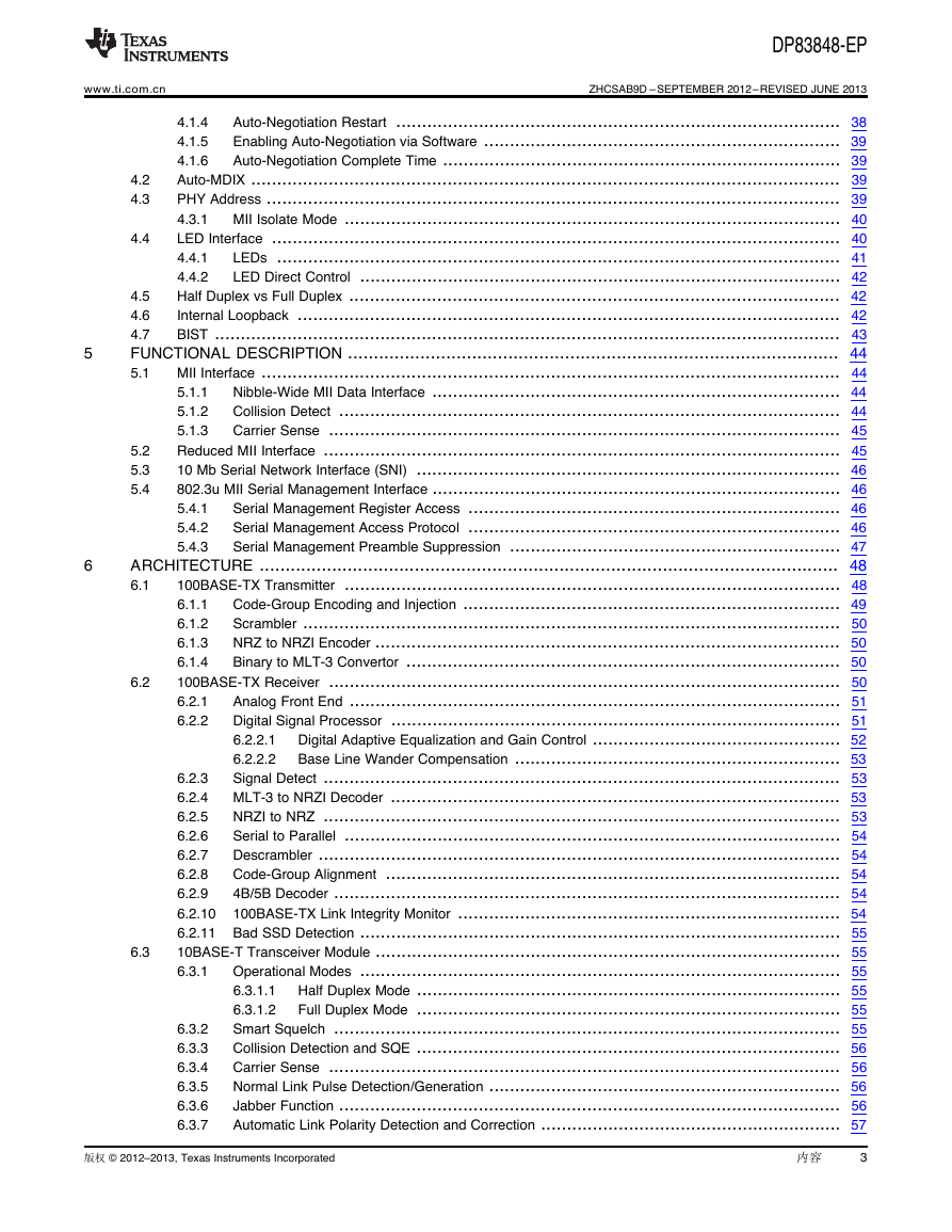
www.ti.com.cn 5 6 6.2 6.3 DP83848-EP 4.2 4.3 4.4 5.2 5.3 5.4 ZHCSAB9D –SEPTEMBER 2012–REVISED JUNE 2013 Auto-Negotiation Restart ...................................................................................... 38 4.1.4 Enabling Auto-Negotiation via Software ..................................................................... 39 4.1.5 Auto-Negotiation Complete Time ............................................................................. 39 4.1.6 Auto-MDIX .................................................................................................................. 39 PHY Address ............................................................................................................... 39 MII Isolate Mode ................................................................................................ 40 4.3.1 LED Interface .............................................................................................................. 40 LEDs ............................................................................................................. 41 4.4.1 LED Direct Control ............................................................................................. 42 4.4.2 Half Duplex vs Full Duplex ............................................................................................... 42 4.5 Internal Loopback ......................................................................................................... 42 4.6 BIST ......................................................................................................................... 43 4.7 FUNCTIONAL DESCRIPTION ............................................................................................... 44 MII Interface ................................................................................................................ 44 5.1 Nibble-Wide MII Data Interface ............................................................................... 44 5.1.1 Collision Detect ................................................................................................. 44 5.1.2 Carrier Sense ................................................................................................... 45 5.1.3 Reduced MII Interface .................................................................................................... 45 10 Mb Serial Network Interface (SNI) .................................................................................. 46 802.3u MII Serial Management Interface ............................................................................... 46 Serial Management Register Access ........................................................................ 46 5.4.1 Serial Management Access Protocol ........................................................................ 46 5.4.2 Serial Management Preamble Suppression ................................................................ 47 5.4.3 ARCHITECTURE ................................................................................................................ 48 100BASE-TX Transmitter ................................................................................................ 48 6.1 Code-Group Encoding and Injection ......................................................................... 49 6.1.1 Scrambler ........................................................................................................ 50 6.1.2 NRZ to NRZI Encoder .......................................................................................... 50 6.1.3 Binary to MLT-3 Convertor .................................................................................... 50 6.1.4 100BASE-TX Receiver ................................................................................................... 50 Analog Front End ............................................................................................... 51 6.2.1 Digital Signal Processor ....................................................................................... 51 6.2.2 Digital Adaptive Equalization and Gain Control ................................................ 52 6.2.2.1 Base Line Wander Compensation ............................................................... 53 6.2.2.2 Signal Detect .................................................................................................... 53 6.2.3 MLT-3 to NRZI Decoder ....................................................................................... 53 6.2.4 NRZI to NRZ .................................................................................................... 53 6.2.5 Serial to Parallel ................................................................................................ 54 6.2.6 Descrambler ..................................................................................................... 54 6.2.7 Code-Group Alignment ........................................................................................ 54 6.2.8 4B/5B Decoder .................................................................................................. 54 6.2.9 100BASE-TX Link Integrity Monitor .......................................................................... 54 6.2.10 6.2.11 Bad SSD Detection ............................................................................................. 55 10BASE-T Transceiver Module .......................................................................................... 55 Operational Modes ............................................................................................. 55 6.3.1 Half Duplex Mode .................................................................................. 55 6.3.1.1 Full Duplex Mode .................................................................................. 55 6.3.1.2 Smart Squelch .................................................................................................. 55 Collision Detection and SQE .................................................................................. 56 Carrier Sense ................................................................................................... 56 Normal Link Pulse Detection/Generation .................................................................... 56 Jabber Function ................................................................................................. 56 Automatic Link Polarity Detection and Correction .......................................................... 57 6.3.2 6.3.3 6.3.4 6.3.5 6.3.6 6.3.7 版权 © 2012–2013, Texas Instruments Incorporated 内容 3
DP83848-EP ZHCSAB9D –SEPTEMBER 2012–REVISED JUNE 2013 7 8 9 7.4 7.5 www.ti.com.cn Transmit and Receive Filtering ............................................................................... 57 6.3.8 Transmitter ...................................................................................................... 57 6.3.9 6.3.10 Receiver ......................................................................................................... 57 DESIGN GUIDELINES ......................................................................................................... 58 TPI Network Circuit ........................................................................................................ 58 7.1 ESD Protection ............................................................................................................ 58 7.2 Clock In (X1) Requirements .............................................................................................. 58 7.3 Oscillator ......................................................................................................... 58 7.3.1 Crystal ............................................................................................................ 59 7.3.2 Power Feedback Circuit .................................................................................................. 60 Power Down and Interrupt ............................................................................................... 60 Power Down Control Mode .................................................................................... 60 7.5.1 Interrupt Mechanisms .......................................................................................... 60 7.5.2 Energy Detect Mode ...................................................................................................... 61 7.6 Thermal Vias Recommendation ......................................................................................... 61 7.7 RESET OPERATION ........................................................................................................... 62 Hardware Reset ........................................................................................................... 62 8.1 Software Reset ............................................................................................................ 62 8.2 REGISTER BLOCK ............................................................................................................. 63 ................................................................................................................................ 63 9.1 Register Definition ......................................................................................................... 67 9.2 Basic Mode Control Register (BMCR) ....................................................................... 67 9.2.1 Basic Mode Status Register (BMSR) ........................................................................ 68 9.2.2 PHY Identifier Register #1 (PHYIDR1) ...................................................................... 69 9.2.3 PHY Identifier Register #2 (PHYIDR2) ...................................................................... 69 9.2.4 Auto-Negotiation Advertisement Register (ANAR) ......................................................... 70 9.2.5 Auto-Negotiation Link Partner Ability Register (ANLPAR) (BASE Page) ............................... 71 9.2.6 Auto-Negotiation Link Partner Ability Register (ANLPAR) (Next Page) ................................. 71 9.2.7 Auto-Negotiate Expansion Register (ANER) ................................................................ 72 9.2.8 Auto-Negotiation Next Page Transmit Register (ANNPTR) ............................................... 73 9.2.9 Extended Registers ....................................................................................................... 73 PHY Status Register (PHYSTS) .............................................................................. 73 9.3.1 MII Interrupt Control Register (MICR) ........................................................................ 75 9.3.2 MII Interrupt Status and Miscellaneous Control Register (MISR) ........................................ 76 9.3.3 False Carrier Sense Counter Register (FCSCR) ........................................................... 77 9.3.4 Receiver Error Counter Register (RECR) ................................................................... 77 9.3.5 100 Mb/s PCS Configuration and Status Register (PCSR) ............................................... 77 9.3.6 RMII and Bypass Register (RBR) ............................................................................ 78 9.3.7 LED Direct Control Register (LEDCR) ....................................................................... 79 9.3.8 PHY Control Register (PHYCR) .............................................................................. 79 9.3.9 10Base-T Status/Control Register (10BTSCR) ............................................................. 81 9.3.10 9.3.11 CD Test and BIST Extensions Register (CDCTRL1) ...................................................... 82 9.3.12 Energy Detect Control (EDCR) ............................................................................... 82 9.3 4 内容 版权 © 2012–2013, Texas Instruments Incorporated
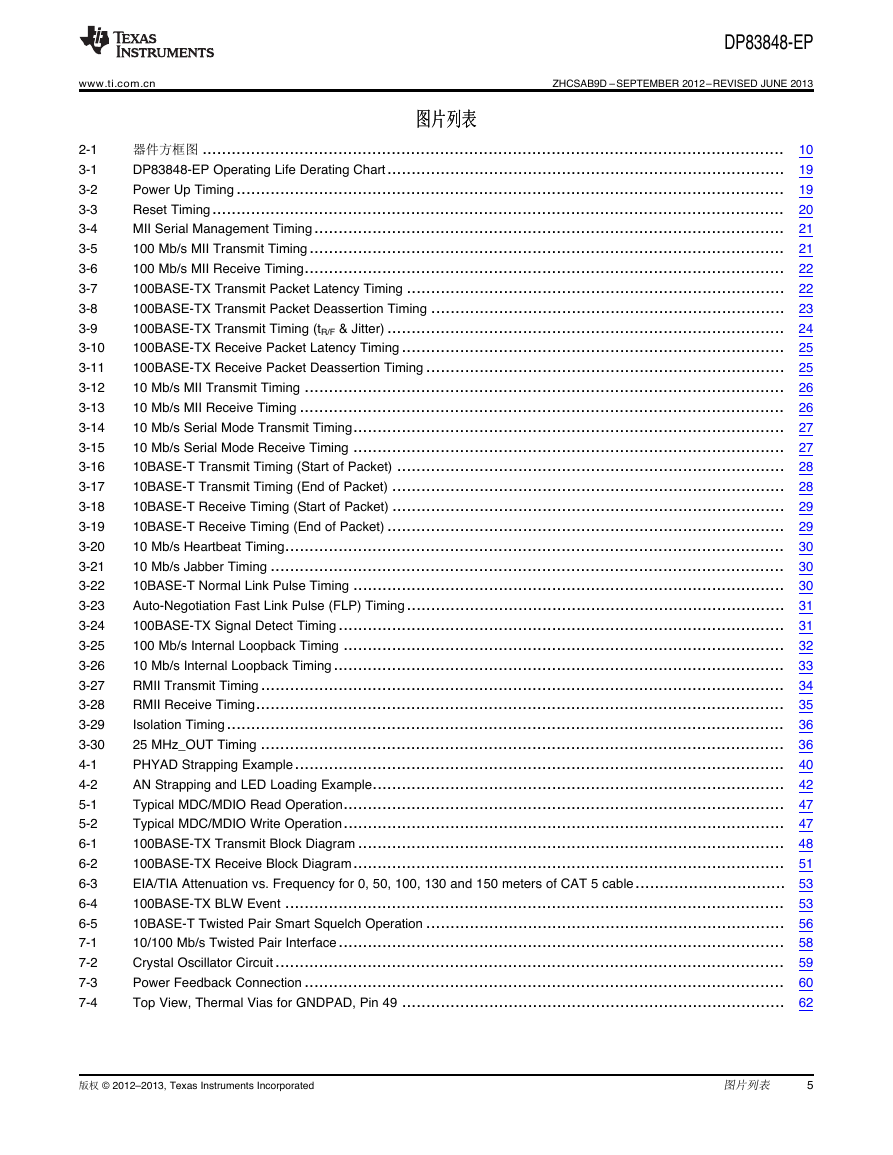
DP83848-EP www.ti.com.cn ZHCSAB9D –SEPTEMBER 2012–REVISED JUNE 2013 图图片片列列表表 器件方框图 ........................................................................................................................ 10 DP83848-EP Operating Life Derating Chart.................................................................................. 19 Power Up Timing ................................................................................................................. 19 Reset Timing...................................................................................................................... 20 MII Serial Management Timing................................................................................................. 21 100 Mb/s MII Transmit Timing.................................................................................................. 21 100 Mb/s MII Receive Timing................................................................................................... 22 100BASE-TX Transmit Packet Latency Timing .............................................................................. 22 100BASE-TX Transmit Packet Deassertion Timing ......................................................................... 23 100BASE-TX Transmit Timing (tR/F & Jitter) .................................................................................. 24 100BASE-TX Receive Packet Latency Timing............................................................................... 25 100BASE-TX Receive Packet Deassertion Timing .......................................................................... 25 10 Mb/s MII Transmit Timing ................................................................................................... 26 10 Mb/s MII Receive Timing .................................................................................................... 26 10 Mb/s Serial Mode Transmit Timing......................................................................................... 27 10 Mb/s Serial Mode Receive Timing ......................................................................................... 27 10BASE-T Transmit Timing (Start of Packet) ................................................................................ 28 10BASE-T Transmit Timing (End of Packet) ................................................................................. 28 10BASE-T Receive Timing (Start of Packet) ................................................................................. 29 10BASE-T Receive Timing (End of Packet) .................................................................................. 29 10 Mb/s Heartbeat Timing....................................................................................................... 30 10 Mb/s Jabber Timing .......................................................................................................... 30 10BASE-T Normal Link Pulse Timing ......................................................................................... 30 Auto-Negotiation Fast Link Pulse (FLP) Timing.............................................................................. 31 100BASE-TX Signal Detect Timing............................................................................................ 31 100 Mb/s Internal Loopback Timing ........................................................................................... 32 10 Mb/s Internal Loopback Timing............................................................................................. 33 RMII Transmit Timing............................................................................................................ 34 RMII Receive Timing............................................................................................................. 35 Isolation Timing................................................................................................................... 36 25 MHz_OUT Timing ............................................................................................................ 36 PHYAD Strapping Example..................................................................................................... 40 AN Strapping and LED Loading Example..................................................................................... 42 Typical MDC/MDIO Read Operation........................................................................................... 47 Typical MDC/MDIO Write Operation........................................................................................... 47 100BASE-TX Transmit Block Diagram ........................................................................................ 48 100BASE-TX Receive Block Diagram......................................................................................... 51 EIA/TIA Attenuation vs. Frequency for 0, 50, 100, 130 and 150 meters of CAT 5 cable............................... 53 100BASE-TX BLW Event ....................................................................................................... 53 10BASE-T Twisted Pair Smart Squelch Operation .......................................................................... 56 10/100 Mb/s Twisted Pair Interface............................................................................................ 58 Crystal Oscillator Circuit......................................................................................................... 59 Power Feedback Connection ................................................................................................... 60 Top View, Thermal Vias for GNDPAD, Pin 49 ............................................................................... 62 2-1 3-1 3-2 3-3 3-4 3-5 3-6 3-7 3-8 3-9 3-10 3-11 3-12 3-13 3-14 3-15 3-16 3-17 3-18 3-19 3-20 3-21 3-22 3-23 3-24 3-25 3-26 3-27 3-28 3-29 3-30 4-1 4-2 5-1 5-2 6-1 6-2 6-3 6-4 6-5 7-1 7-2 7-3 7-4 版权 © 2012–2013, Texas Instruments Incorporated 图片列表 5
DP83848-EP ZHCSAB9D –SEPTEMBER 2012–REVISED JUNE 2013 www.ti.com.cn 图图表表列列表表 串行管理接口...................................................................................................................... 12 MAC 数据接口 .................................................................................................................... 12 时钟接口 ........................................................................................................................... 13 LED 接口 .......................................................................................................................... 14 JTAG 接口......................................................................................................................... 14 复位和断电 ........................................................................................................................ 14 捆绑选项 ........................................................................................................................... 15 10Mb/s 和 100Mb/s PMD 接口 ................................................................................................. 15 特别连接 ........................................................................................................................... 16 电源引脚 ........................................................................................................................... 16 Auto-Negotiation Modes......................................................................................................... 37 PHY Address Mapping .......................................................................................................... 39 LED Mode Select................................................................................................................. 41 Supported Packet Sizes at ±50ppm and ±100ppm for Each Clock ....................................................... 45 Typical MDIO Frame Format ................................................................................................... 47 4B5B Code-Group Encoding or Decoding .................................................................................... 49 25 MHz Oscillator Specification ................................................................................................ 59 50 MHz Oscillator Specification ................................................................................................ 59 25 MHz Crystal Specification ................................................................................................... 60 Register Map...................................................................................................................... 63 Register Table .................................................................................................................... 64 Basic Mode Control Register (BMCR), Address 0x00....................................................................... 67 Basic Mode Status Register (BMSR), Address 0x01........................................................................ 68 PHY Identifier Register #1 (PHYIDR1), Address 0x02 ...................................................................... 69 PHY Identifier Register #2 (PHYIDR2), Address 0x03 ...................................................................... 69 Negotiation Advertisement Register (ANAR), Address 0x04 ............................................................... 70 Auto-Negotiation Link Partner Ability Register (ANLPAR) (BASE Page), Address 0x05 ............................... 71 Auto-Negotiation Link Partner Ability Register (ANLPAR) (Next Page), Address 0x05................................. 71 Auto-Negotiate Expansion Register (ANER), Address 0x06 ............................................................... 72 Auto-Negotiation Next Page Transmit Register (ANNPTR), Address 0x07 .............................................. 73 PHY Status Register (PHYSTS), Address 0x10 ............................................................................. 73 MII Interrupt Control Register (MICR), Address 0x11 ....................................................................... 75 MII Interrupt Status and Miscellaneous Control Register (MISR), Address 0x12........................................ 76 False Carrier Sense Counter Register (FCSCR), Address 0x14 .......................................................... 77 Receiver Error Counter Register (RECR), Address 0x15................................................................... 77 100 Mb/s PCS Configuration and Status Register (PCSR), Address 0x16............................................... 77 RMII and Bypass Register (RBR), Addresses 0x17 ......................................................................... 78 LED Direct Control Register (LEDCR), Address 0x18 ...................................................................... 79 PHY Control Register (PHYCR), Address 0x19.............................................................................. 79 10Base-T Status/Control Register (10BTSCR), Address 0x1A ............................................................ 81 CD Test and BIST Extensions Register (CDCTRL1), Address 0x1B ..................................................... 82 Energy Detect Control (EDCR), Address 0x1D .............................................................................. 82 2-1 2-2 2-3 2-4 2-5 2-6 2-7 2-8 2-9 2-10 4-1 4-2 4-3 5-1 5-2 6-1 7-1 7-2 7-3 9-1 9-2 9-3 9-4 9-5 9-6 9-7 9-8 9-9 9-10 9-11 9-12 9-13 9-14 9-15 9-16 9-17 9-18 9-19 9-20 9-21 9-22 9-23 6 图表列表 版权 © 2012–2013, Texas Instruments Incorporated
DP83848-EP www.ti.com.cn ZHCSAB9D –SEPTEMBER 2012–REVISED JUNE 2013 PHYTER™ 军军用用温温度度单单端端口口 10/100 MB/S 以以太太网网物物理理层层收收发发器器 查查询询样样片片: DP83848-EP 1 介介绍绍 1.1 特特性性 12• 低低功功耗耗 3.3V,,0.18μm CMOS 技技术术 • 低低功功耗耗::小小于于 270mW((典典型型值值)) • 3.3V MAC 接接口口 • 针针对对 10/100Mb/s 的的自自动动 MDIX • 能能量量检检测测模模式式 • 25MHz 时时钟钟输输出出 • SNI 接接口口((可可配配置置)) • RMII 修修订订版版本本 1.2 接接口口((可可配配置置)) • MII 串串行行管管理理接接口口((MDC 和和 MDIO)) • • • • • • 集集成成的的与与 ANSI X3.263 兼兼容容的的双双绞绞线线物物理理媒媒介介相相关关 (TP-PMD) 物物理理子子层层,,此此子子层层具具有有自自适适应应均均衡衡和和基基线线漂漂移移补补 IEEE 802.3u MII IEEE 802.3u 自自动动协协商商和和并并行行检检测测 IEEE 802.3u ENDEC,,10BASE-T 收收发发器器和和滤滤波波器器 IEEE 802.3u PCS,,100BASE-TX 收收发发器器和和滤滤波波器器 IEEE 1149.1 JTAG 偿偿 • 长长达达 150 米米的的无无故故障障运运行行 • 可可编编程程 LED 支支持持链链路路,,10/100Mb/s 模模式式,,活活动动和和冲冲突突检检测测 • 针针对对完完整整 PHY 状状态态的的单单寄寄存存器器访访问问 • 10/100Mbs 数数据据包包 BIST((内内置置自自检检)) • 无无铅铅 48 引引脚脚塑塑料料四四方方扁扁平平 (PQFP) 封封装装 (7mm) x (7mm) 1.2 应应用用范范围围 • 汽汽车车和和运运输输 • 工工业业控控制制和和工工厂厂自自动动化化 • 通通用用嵌嵌入入式式应应用用 1.3 支支持持国国防防、、航航天天和和医医疗疗应应用用 • 受受控控基基线线 • 同同一一组组装装和和测测试试场场所所 • 同同一一制制造造场场所所 • 军军用用温温度度范范围围((-55°C 至至 125°C)) • 延延长长的的产产品品生生命命周周期期 • 延延长长的的产产品品变变更更通通知知 • 产产品品可可追追溯溯性性 1 Please be aware that an important notice concerning availability, standard warranty, and use in critical applications of Texas Instruments semiconductor products and disclaimers thereto appears at the end of this data sheet. 2PHYTER is a trademark of Texas Instruments. PRODUCTION DATA information is current as of publication date. Products conform to specifications per the terms of the Texas Instruments standard warranty. Production processing does not necessarily include testing of all parameters. 版权 © 2012–2013, Texas Instruments Incorporated English Data Sheet: SLLSEC6
DP83848-EP ZHCSAB9D –SEPTEMBER 2012–REVISED JUNE 2013 www.ti.com.cn 1.4 典典型型系系统统图图 8 介绍 版权 © 2012–2013, Texas Instruments Incorporated MPU/CPUMediaAccess ControllerMII/RMII/SNIMagneticsRJ-45DP8384810/100 MB/S10Base-Tor100Base-TStatusLEDs25-MHZClockSourceTypicalApplication
分享到:
收藏