fitipower integrated technology Inc.
JD9365D
Data Sheet
800RGB x 1280 dot, 16.7M color,
without internal GRAM, a-Si TFT LCD Single Chip Driver
Preliminary Version 0.01
2017/4/27
Confidential Copyright © fitipower integrated technology Inc.
�
Preliminary V0.01
JD9365D
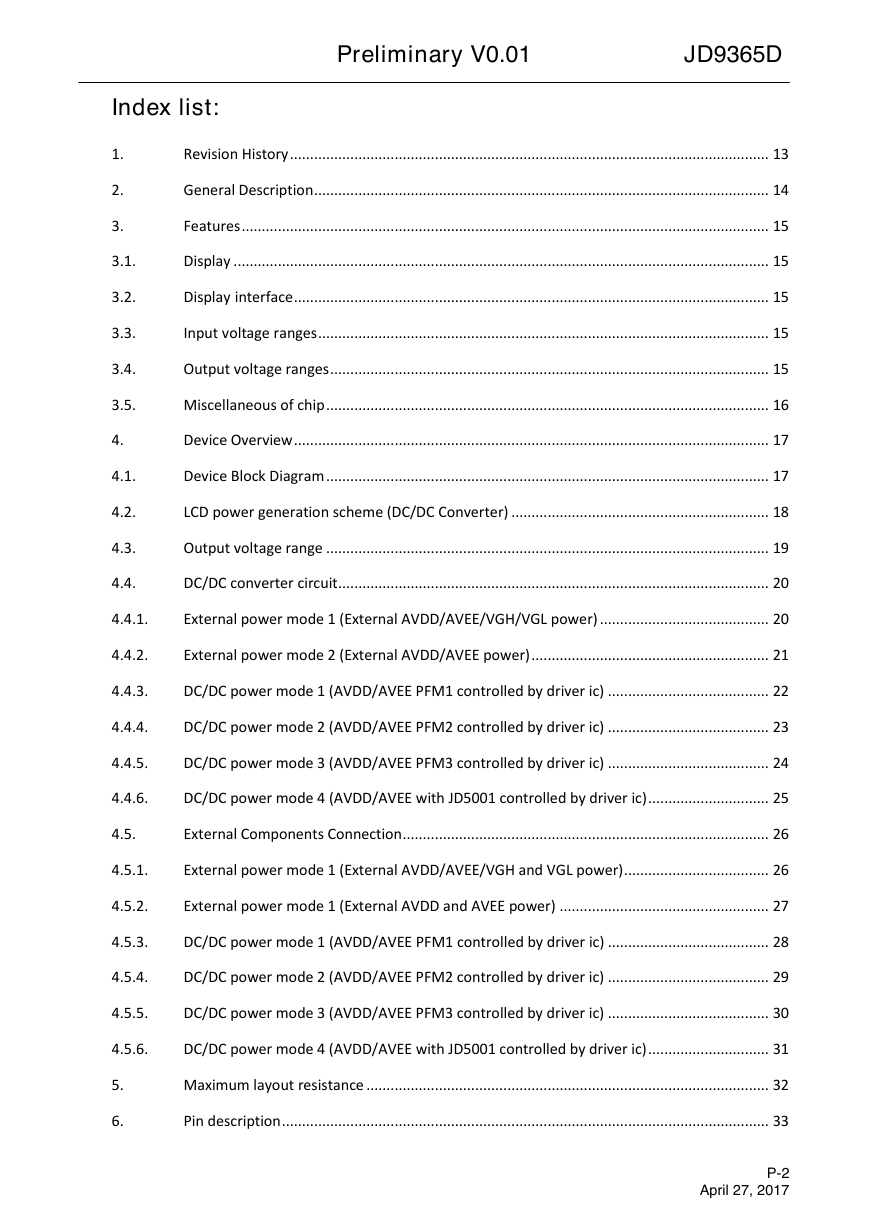
Index list:
1.
2.
3.
3.1.
3.2.
3.3.
3.4.
3.5.
4.
4.1.
4.2.
4.3.
4.4.
Revision History ....................................................................................................................... 13
General Description ................................................................................................................. 14
Features ................................................................................................................................... 15
Display ..................................................................................................................................... 15
Display interface ...................................................................................................................... 15
Input voltage ranges ................................................................................................................ 15
Output voltage ranges ............................................................................................................. 15
Miscellaneous of chip .............................................................................................................. 16
Device Overview ...................................................................................................................... 17
Device Block Diagram .............................................................................................................. 17
LCD power generation scheme (DC/DC Converter) ................................................................ 18
Output voltage range .............................................................................................................. 19
DC/DC converter circuit ........................................................................................................... 20
4.4.1.
External power mode 1 (External AVDD/AVEE/VGH/VGL power) .......................................... 20
4.4.2.
External power mode 2 (External AVDD/AVEE power) ........................................................... 21
4.4.3.
DC/DC power mode 1 (AVDD/AVEE PFM1 controlled by driver ic) ........................................ 22
4.4.4.
DC/DC power mode 2 (AVDD/AVEE PFM2 controlled by driver ic) ........................................ 23
4.4.5.
DC/DC power mode 3 (AVDD/AVEE PFM3 controlled by driver ic) ........................................ 24
4.4.6.
DC/DC power mode 4 (AVDD/AVEE with JD5001 controlled by driver ic) .............................. 25
4.5.
External Components Connection ........................................................................................... 26
4.5.1.
External power mode 1 (External AVDD/AVEE/VGH and VGL power) .................................... 26
4.5.2.
External power mode 1 (External AVDD and AVEE power) .................................................... 27
4.5.3.
DC/DC power mode 1 (AVDD/AVEE PFM1 controlled by driver ic) ........................................ 28
4.5.4.
DC/DC power mode 2 (AVDD/AVEE PFM2 controlled by driver ic) ........................................ 29
4.5.5.
DC/DC power mode 3 (AVDD/AVEE PFM3 controlled by driver ic) ........................................ 30
4.5.6.
DC/DC power mode 4 (AVDD/AVEE with JD5001 controlled by driver ic) .............................. 31
5.
6.
Maximum layout resistance .................................................................................................... 32
Pin description ......................................................................................................................... 33
P-2
April 27, 2017
�
7.
7.1.
Preliminary V0.01
JD9365D
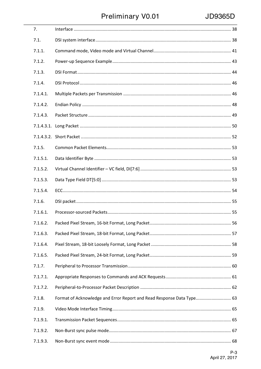
Interface .................................................................................................................................. 38
DSI system interface ................................................................................................................ 38
7.1.1.
Command mode, Video mode and Virtual Channel ................................................................ 41
7.1.2.
Power-up Sequence Example .................................................................................................. 43
7.1.3.
DSI Format ............................................................................................................................... 44
7.1.4.
DSI Protocol ............................................................................................................................. 46
7.1.4.1. Multiple Packets per Transmission ......................................................................................... 46
7.1.4.2.
Endian Policy ........................................................................................................................... 48
7.1.4.3.
Packet Structure ...................................................................................................................... 49
7.1.4.3.1. Long Packet ............................................................................................................................. 50
7.1.4.3.2. Short Packet ............................................................................................................................ 52
7.1.5.
Common Packet Elements....................................................................................................... 53
7.1.5.1. Data Identifier Byte ................................................................................................................. 53
7.1.5.2.
Virtual Channel Identifier – VC field, DI[7:6] ........................................................................... 53
7.1.5.3. Data Type Field DT[5:0] ........................................................................................................... 53
7.1.5.4.
ECC ........................................................................................................................................... 54
7.1.6.
DSI packet ................................................................................................................................ 55
7.1.6.1.
Processor-sourced Packets ...................................................................................................... 55
7.1.6.2.
Packed Pixel Stream, 16-bit Format, Long Packet ................................................................... 56
7.1.6.3.
Packed Pixel Stream, 18-bit Format, Long Packet ................................................................... 57
7.1.6.4.
Pixel Stream, 18-bit Loosely Format, Long Packet .................................................................. 58
7.1.6.5.
Packed Pixel Stream, 24-bit Format, Long Packet ................................................................... 59
7.1.7.
Peripheral to Processor Transmission ..................................................................................... 60
7.1.7.1.
Appropriate Responses to Commands and ACK Requests ...................................................... 61
7.1.7.2.
Peripheral-to-Processor Packet Description ........................................................................... 62
7.1.8.
Format of Acknowledge and Error Report and Read Response Data Type ............................. 63
7.1.9.
Video Mode Interface Timing .................................................................................................. 65
7.1.9.1.
Transmission Packet Sequences .............................................................................................. 65
7.1.9.2. Non-Burst sync pulse mode..................................................................................................... 67
7.1.9.3. Non-Burst sync event mode .................................................................................................... 68
P-3
April 27, 2017
�
Preliminary V0.01
JD9365D
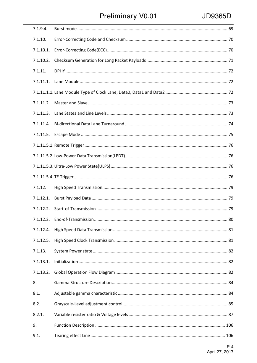
7.1.9.4.
Burst mode .............................................................................................................................. 69
7.1.10.
Error-Correcting Code and Checksum ..................................................................................... 70
7.1.10.1. Error-Correcting Code(ECC) ..................................................................................................... 70
7.1.10.2. Checksum Generation for Long Packet Payloads .................................................................... 71
7.1.11.
DPHY ........................................................................................................................................ 72
7.1.11.1. Lane Module ............................................................................................................................ 72
7.1.11.1.1. Lane Module Type of Clock Lane, Data0, Data1 and Data2 .................................................... 72
7.1.11.2. Master and Slave ..................................................................................................................... 73
7.1.11.3. Lane States and Line Levels ..................................................................................................... 73
7.1.11.4. Bi-directional Data Lane Turnaround ...................................................................................... 74
7.1.11.5. Escape Mode ........................................................................................................................... 75
7.1.11.5.1. Remote Trigger ........................................................................................................................ 76
7.1.11.5.2. Low-Power Data Transmission(LPDT)...................................................................................... 76
7.1.11.5.3. Ultra-Low Power State(ULPS) .................................................................................................. 76
7.1.11.5.4. TE Trigger ................................................................................................................................. 76
7.1.12.
High Speed Transmission......................................................................................................... 79
7.1.12.1. Burst Payload Data .................................................................................................................. 79
7.1.12.2. Start-of-Transmission .............................................................................................................. 79
7.1.12.3. End-of-Transmission ................................................................................................................ 80
7.1.12.4. High Speed Data Transmission ................................................................................................ 81
7.1.12.5. High Speed Clock Transmission ............................................................................................... 81
7.1.13.
System Power state ................................................................................................................. 82
7.1.13.1.
Initialization ............................................................................................................................. 82
7.1.13.2. Global Operation Flow Diagram .............................................................................................. 82
8.
8.1.
8.2.
Gamma Structure Description ................................................................................................. 84
Adjustable gamma characteristic ............................................................................................ 84
Grayscale-Level adjustment control ........................................................................................ 85
8.2.1.
Variable resister ratio & Voltage levels ................................................................................... 87
9.
9.1.
Function Description ............................................................................................................. 106
Tearing effect Line ................................................................................................................. 106
P-4
April 27, 2017
�
Preliminary V0.01
JD9365D
9.1.1.
Tearing effect Line mode ....................................................................................................... 106
9.1.2.
Tearing effect line timing ...................................................................................................... 108
9.2.
9.3.
9.4.
Oscillator ................................................................................................................................ 109
Output pins Characteristics ................................................................................................... 110
Self-diagnostic Functions ....................................................................................................... 111
9.4.1.
Register loading detection .................................................................................................... 111
9.4.2.
Functionality Detection ......................................................................................................... 112
9.5.
Power on/off sequence ......................................................................................................... 113
9.5.1.
General .................................................................................................................................. 113
9.5.2.
Power on/off sequence for differential power mode ........................................................... 114
9.6.
9.7.
Uncontrolled power off ......................................................................................................... 117
Content adaptive brightness control (CABC) function .......................................................... 118
9.7.1.
Definition of the CABC ........................................................................................................... 118
9.7.2.
Transition Time of the CABC .................................................................................................. 119
9.7.3.
Minimum brightness setting of CABC function ..................................................................... 122
10.
Command .............................................................................................................................. 123
10.1.
Command List ........................................................................................................................ 123
10.1.1.
Standard command ............................................................................................................... 123
10.1.2.
Standard Command Accessibility .......................................................................................... 126
10.1.3.
Standard Command Default Modes and Values ................................................................... 127
10.2.
Command Description ........................................................................................................... 128
10.2.1.
NOP (00h) .............................................................................................................................. 128
10.2.2.
SWRESET: Software Reset (01h) ............................................................................................ 129
10.2.3.
RDDIDIF: Read Display Identification Information (04h) ....................................................... 130
10.2.4.
RDNUMPE: Read number of the parity errors (05h) ............................................................. 131
10.2.5.
REDRD: Read Red Color (06h) ............................................................................................... 132
10.2.6.
REDGREEN: Read Green Color (07h) ..................................................................................... 133
10.2.7.
REDBLUE: Read Blue Color (08h) ........................................................................................... 134
10.2.8.
RDDST: Read Display Status (09h) ......................................................................................... 135
10.2.9.
RDDPM: Read Display Power Mode (0Ah) ............................................................................ 137
P-5
April 27, 2017
�
Preliminary V0.01
JD9365D
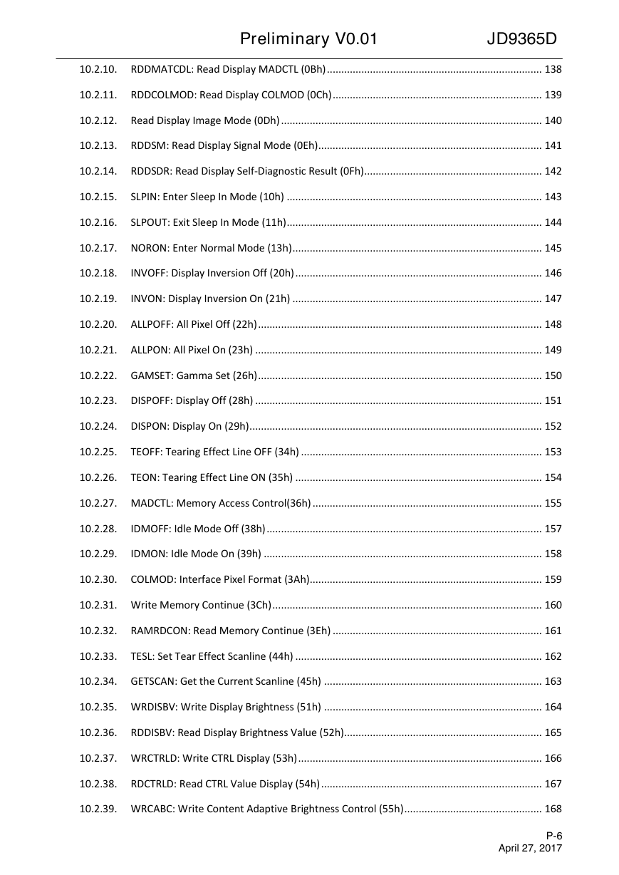
10.2.10. RDDMATCDL: Read Display MADCTL (0Bh) ........................................................................... 138
10.2.11. RDDCOLMOD: Read Display COLMOD (0Ch) ......................................................................... 139
10.2.12. Read Display Image Mode (0Dh) ........................................................................................... 140
10.2.13. RDDSM: Read Display Signal Mode (0Eh) .............................................................................. 141
10.2.14. RDDSDR: Read Display Self-Diagnostic Result (0Fh) .............................................................. 142
10.2.15.
SLPIN: Enter Sleep In Mode (10h) ......................................................................................... 143
10.2.16.
SLPOUT: Exit Sleep In Mode (11h) ......................................................................................... 144
10.2.17. NORON: Enter Normal Mode (13h) ....................................................................................... 145
10.2.18.
INVOFF: Display Inversion Off (20h) ...................................................................................... 146
10.2.19.
INVON: Display Inversion On (21h) ....................................................................................... 147
10.2.20. ALLPOFF: All Pixel Off (22h) ................................................................................................... 148
10.2.21. ALLPON: All Pixel On (23h) .................................................................................................... 149
10.2.22. GAMSET: Gamma Set (26h) ................................................................................................... 150
10.2.23. DISPOFF: Display Off (28h) .................................................................................................... 151
10.2.24. DISPON: Display On (29h) ...................................................................................................... 152
10.2.25. TEOFF: Tearing Effect Line OFF (34h) .................................................................................... 153
10.2.26. TEON: Tearing Effect Line ON (35h) ...................................................................................... 154
10.2.27. MADCTL: Memory Access Control(36h) ................................................................................ 155
10.2.28.
IDMOFF: Idle Mode Off (38h) ................................................................................................ 157
10.2.29.
IDMON: Idle Mode On (39h) ................................................................................................. 158
10.2.30. COLMOD: Interface Pixel Format (3Ah)................................................................................. 159
10.2.31. Write Memory Continue (3Ch) .............................................................................................. 160
10.2.32. RAMRDCON: Read Memory Continue (3Eh) ......................................................................... 161
10.2.33. TESL: Set Tear Effect Scanline (44h) ...................................................................................... 162
10.2.34. GETSCAN: Get the Current Scanline (45h) ............................................................................ 163
10.2.35. WRDISBV: Write Display Brightness (51h) ............................................................................ 164
10.2.36. RDDISBV: Read Display Brightness Value (52h)..................................................................... 165
10.2.37. WRCTRLD: Write CTRL Display (53h) ..................................................................................... 166
10.2.38. RDCTRLD: Read CTRL Value Display (54h) ............................................................................. 167
10.2.39. WRCABC: Write Content Adaptive Brightness Control (55h) ................................................ 168
P-6
April 27, 2017
�
Preliminary V0.01
JD9365D
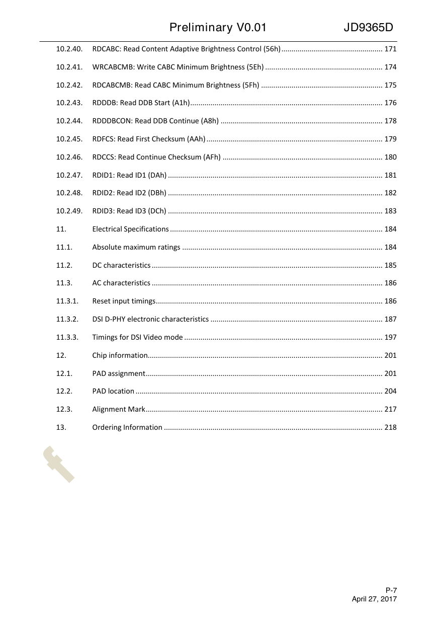
10.2.40. RDCABC: Read Content Adaptive Brightness Control (56h) .................................................. 171
10.2.41. WRCABCMB: Write CABC Minimum Brightness (5Eh) .......................................................... 174
10.2.42. RDCABCMB: Read CABC Minimum Brightness (5Fh) ............................................................ 175
10.2.43. RDDDB: Read DDB Start (A1h) ............................................................................................... 176
10.2.44. RDDDBCON: Read DDB Continue (A8h) ................................................................................ 178
10.2.45. RDFCS: Read First Checksum (AAh) ....................................................................................... 179
10.2.46. RDCCS: Read Continue Checksum (AFh) ............................................................................... 180
10.2.47. RDID1: Read ID1 (DAh) .......................................................................................................... 181
10.2.48. RDID2: Read ID2 (DBh) .......................................................................................................... 182
10.2.49. RDID3: Read ID3 (DCh) .......................................................................................................... 183
11.
Electrical Specifications ......................................................................................................... 184
11.1.
Absolute maximum ratings ................................................................................................... 184
11.2.
DC characteristics .................................................................................................................. 185
11.3.
AC characteristics .................................................................................................................. 186
11.3.1.
Reset input timings ................................................................................................................ 186
11.3.2.
DSI D-PHY electronic characteristics ..................................................................................... 187
11.3.3.
Timings for DSI Video mode .................................................................................................. 197
12.
Chip information.................................................................................................................... 201
12.1.
PAD assignment ..................................................................................................................... 201
12.2.
PAD location .......................................................................................................................... 204
12.3.
Alignment Mark ..................................................................................................................... 217
13.
Ordering Information ............................................................................................................ 218
P-7
April 27, 2017
�
Preliminary V0.01
JD9365D
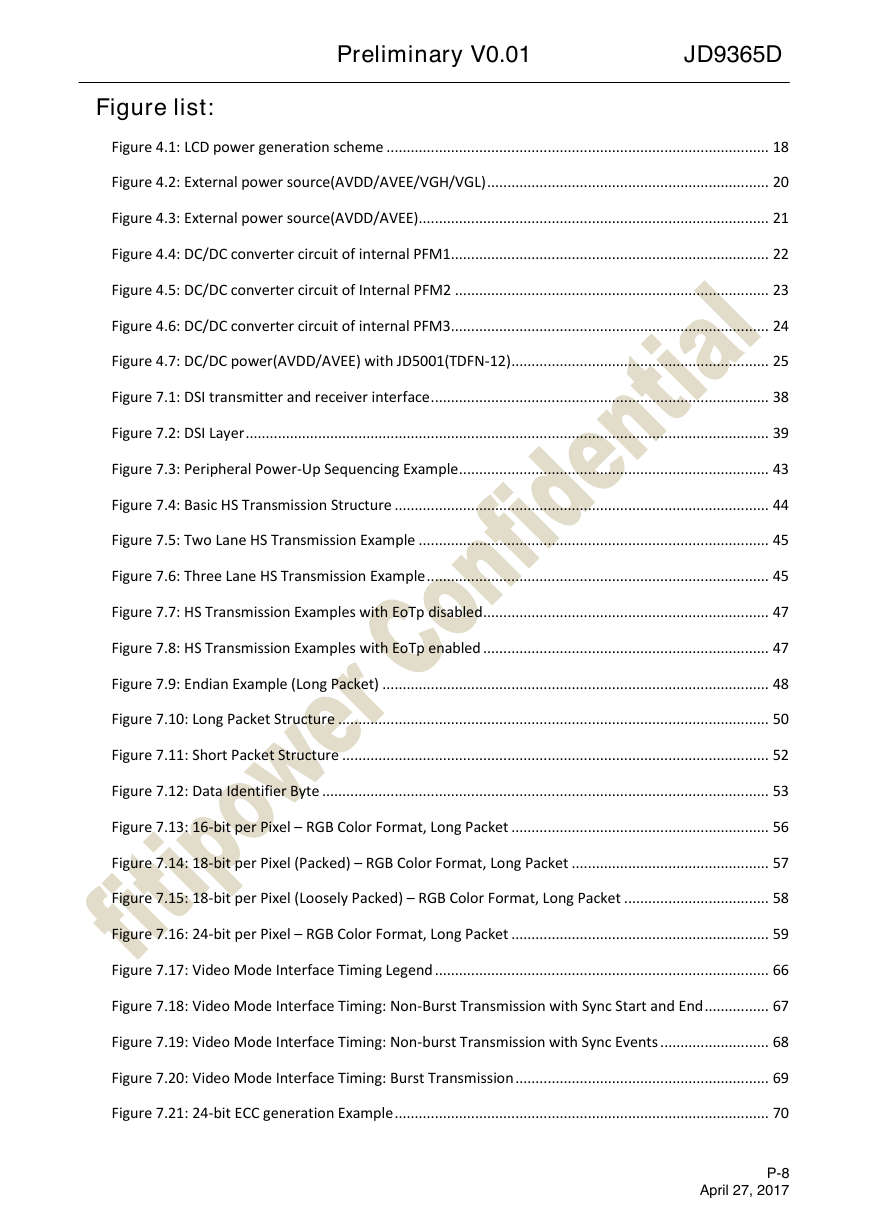
Figure list:
Figure 4.1: LCD power generation scheme ............................................................................................... 18
Figure 4.2: External power source(AVDD/AVEE/VGH/VGL) ...................................................................... 20
Figure 4.3: External power source(AVDD/AVEE) ....................................................................................... 21
Figure 4.4: DC/DC converter circuit of internal PFM1............................................................................... 22
Figure 4.5: DC/DC converter circuit of Internal PFM2 .............................................................................. 23
Figure 4.6: DC/DC converter circuit of internal PFM3............................................................................... 24
Figure 4.7: DC/DC power(AVDD/AVEE) with JD5001(TDFN-12) ................................................................ 25
Figure 7.1: DSI transmitter and receiver interface .................................................................................... 38
Figure 7.2: DSI Layer .................................................................................................................................. 39
Figure 7.3: Peripheral Power-Up Sequencing Example ............................................................................. 43
Figure 7.4: Basic HS Transmission Structure ............................................................................................. 44
Figure 7.5: Two Lane HS Transmission Example ....................................................................................... 45
Figure 7.6: Three Lane HS Transmission Example ..................................................................................... 45
Figure 7.7: HS Transmission Examples with EoTp disabled ....................................................................... 47
Figure 7.8: HS Transmission Examples with EoTp enabled ....................................................................... 47
Figure 7.9: Endian Example (Long Packet) ................................................................................................ 48
Figure 7.10: Long Packet Structure ........................................................................................................... 50
Figure 7.11: Short Packet Structure .......................................................................................................... 52
Figure 7.12: Data Identifier Byte ............................................................................................................... 53
Figure 7.13: 16-bit per Pixel – RGB Color Format, Long Packet ................................................................ 56
Figure 7.14: 18-bit per Pixel (Packed) – RGB Color Format, Long Packet ................................................. 57
Figure 7.15: 18-bit per Pixel (Loosely Packed) – RGB Color Format, Long Packet .................................... 58
Figure 7.16: 24-bit per Pixel – RGB Color Format, Long Packet ................................................................ 59
Figure 7.17: Video Mode Interface Timing Legend ................................................................................... 66
Figure 7.18: Video Mode Interface Timing: Non-Burst Transmission with Sync Start and End ................ 67
Figure 7.19: Video Mode Interface Timing: Non-burst Transmission with Sync Events ........................... 68
Figure 7.20: Video Mode Interface Timing: Burst Transmission ............................................................... 69
Figure 7.21: 24-bit ECC generation Example ............................................................................................. 70
P-8
April 27, 2017
�



 2023年江西萍乡中考道德与法治真题及答案.doc
 2012年重庆南川中考生物真题及答案.doc
 2013年江西师范大学地理学综合及文艺理论基础考研真题.doc
 2020年四川甘孜小升初语文真题及答案I卷.doc
 2020年注册岩土工程师专业基础考试真题及答案.doc
 2023-2024学年福建省厦门市九年级上学期数学月考试题及答案.doc
 2021-2022学年辽宁省沈阳市大东区九年级上学期语文期末试题及答案.doc
 2022-2023学年北京东城区初三第一学期物理期末试卷及答案.doc
 2018上半年江西教师资格初中地理学科知识与教学能力真题及答案.doc
 2012年河北国家公务员申论考试真题及答案-省级.doc
 2020-2021学年江苏省扬州市江都区邵樊片九年级上学期数学第一次质量检测试题及答案.doc
 2022下半年黑龙江教师资格证中学综合素质真题及答案.doc