Getting Started with
Q3D Extractor
®
A 3D PCB Via Model
ANSYS, Inc.
275 Technology Drive
Canonsburg, PA 15317
USA
Tel: (+1) 724-746-3304
Fax: (+1) 724-514-9494
General Information: AnsoftInfo@ansys.com
Technical Support: AnsoftTechSupport@ansys.com
November 2011
Inventory 0000000329
�
The information contained in this document is subject to
change without notice. ANSYS makes no warranty of any kind
with regard to this material, including, but not limited to, the
implied warranties of merchantability and fitness for a partic-
ular purpose. ANSYS shall not be liable for errors contained
herein or for incidental or consequential damages in connec-
tion with the furnishing, performance, or use of this material.
ANSYS, Inc, is a UL registered ISO 9001:2008 company.
Unauthorized use, distribution, or duplication is prohibited.
© 2011 SAS IP, Inc. All rights reserved.
ANSYS and Q3D Extractor are registered trademarks or trade-
marks of SAS IP, Inc. All other trademarks are the property of
their respective owners.
New editions of this manual incorporate all material updated
since the previous edition. The manual printing date, which
indicates the manual’s current edition, changes when a new
edition is printed. Minor corrections and updates that are
incorporated at reprint do not cause the date to change.
Update packages may be issued between editions and contain
additional and/or replacement pages to be merged into the
manual by the user. Pages that are rearranged due to changes
on a previous page are not considered to be revised.
Edition
Date
1
2
3
4
February 2008
April 2010
October 2010
November 2011
Software
Version
8
9
10
11
�
Getting Started with 2D Extractor
Conventions Used in this Guide
Please take a moment to review how instructions and other
useful information are presented in this guide.
• Procedures are presented as numbered lists. A single bul-
let indicates that the procedure has only one step.
• Bold type is used for the following:
- Keyboard entries that should be typed in their entirety exactly
as shown. For example, “copy file1” means to type the word
copy, to type a space, and then to type file1.
- On-screen prompts and messages, names of options and text
boxes, and menu commands.
- Labeled keys on the computer keyboard. For example, “Press
Enter” means to press the key labeled Enter.
• Menu commands are often separated by the “>” symbol.
For example, “Click Draw>Cylinder”.
• Italic type is used for the following:
- Emphasis.
- The titles of publications.
- Keyboard entries when a name or a variable must be typed in
place of the words in italics. For example, “copy file name”
means to type the word copy, to type a space, and then to type
a file name.
• The plus sign (+) is used between keyboard keys to indi-
cate that you should press the keys at the same time. For
example, “Press Shift+F1” means to press the Shift key
and the F1 key at the same time.
Alternate methods
or tips are listed in
the left margin in
blue italic text.
2
�
Getting Started with 2D Extractor
Getting Help
ANSYS Technical Support
To contact ANSYS technical support staff in your geographical
area, please log on to the ANSYS corporate website, https://
www1.ansys.com. You can also contact your ANSYS account
manager in order to obtain this information.
All ANSYS software files are ASCII text and can be sent conve-
niently by e-mail. When reporting difficulties, it is extremely
helpful to include very specific information about what steps
were taken or what stages the simulation reached, including
software files as applicable. This allows more rapid and effec-
tive debugging.
3
�
Getting Started with 2D Extractor
4
�
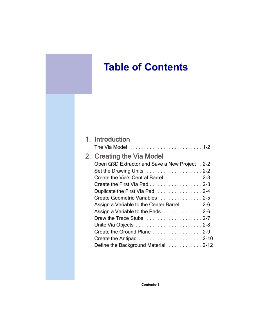
Table of Contents
1. Introduction
The Via Model . . . . . . . . . . . . . . . . . . . . . . . . . . 1-2
2. Creating the Via Model
Open Q3D Extractor and Save a New Project . 2-2
Set the Drawing Units . . . . . . . . . . . . . . . . . . . . 2-2
Create the Via’s Central Barrel . . . . . . . . . . . . . 2-3
Create the First Via Pad . . . . . . . . . . . . . . . . . . . 2-3
Duplicate the First Via Pad . . . . . . . . . . . . . . . . 2-4
Create Geometric Variables . . . . . . . . . . . . . . . 2-5
Assign a Variable to the Center Barrel . . . . . . . 2-6
Assign a Variable to the Pads . . . . . . . . . . . . . . 2-6
Draw the Trace Stubs . . . . . . . . . . . . . . . . . . . . 2-7
Unite Via Objects . . . . . . . . . . . . . . . . . . . . . . . . 2-8
Create the Ground Plane . . . . . . . . . . . . . . . . . . 2-9
Create the Antipad . . . . . . . . . . . . . . . . . . . . . . . 2-10
Define the Background Material . . . . . . . . . . . . 2-12
Contents-1
�
Getting Started with Q3D Extractor: A PCB Via Model
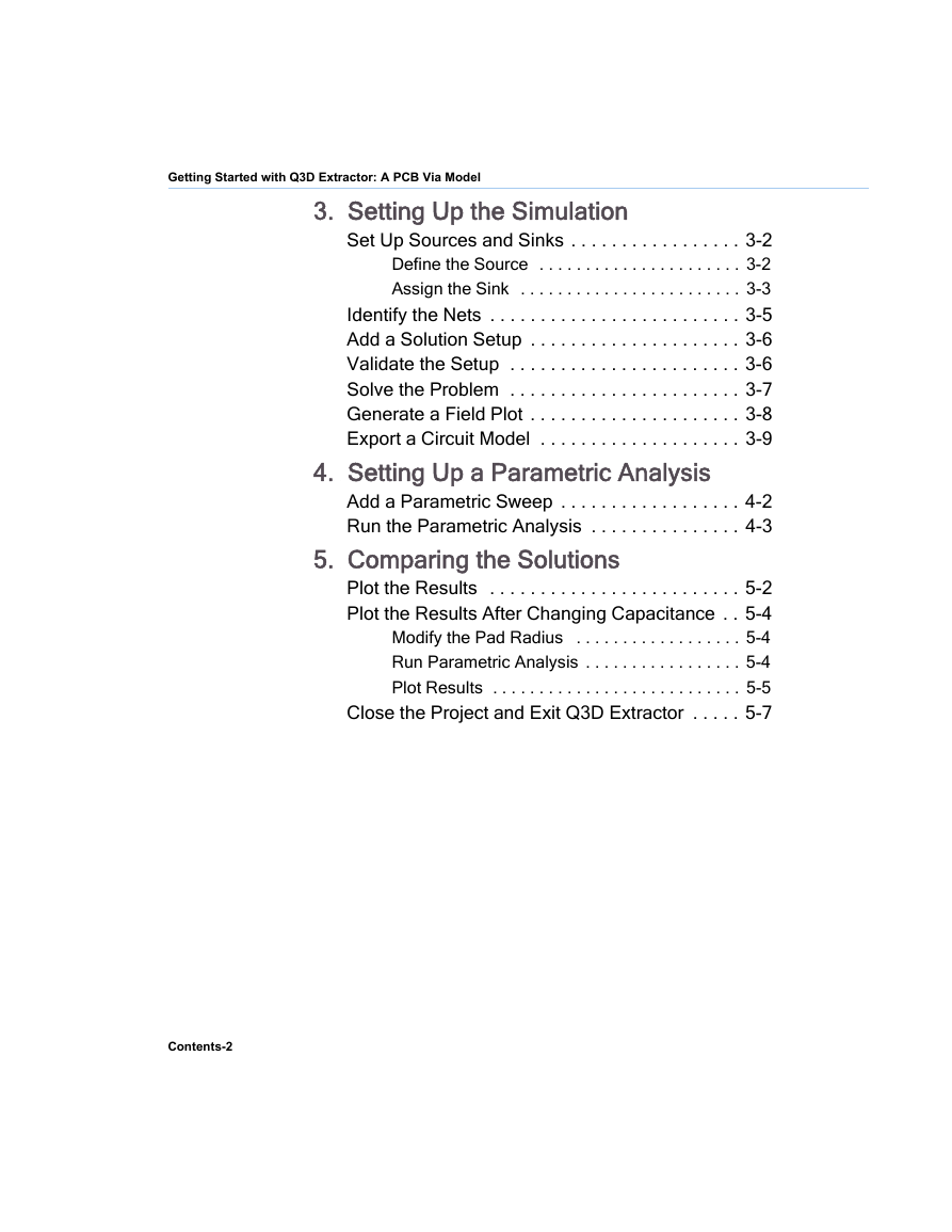
3. Setting Up the Simulation
Set Up Sources and Sinks . . . . . . . . . . . . . . . . . 3-2
Define the Source . . . . . . . . . . . . . . . . . . . . . . 3-2
Assign the Sink . . . . . . . . . . . . . . . . . . . . . . . . 3-3
Identify the Nets . . . . . . . . . . . . . . . . . . . . . . . . . 3-5
Add a Solution Setup . . . . . . . . . . . . . . . . . . . . . 3-6
Validate the Setup . . . . . . . . . . . . . . . . . . . . . . . 3-6
Solve the Problem . . . . . . . . . . . . . . . . . . . . . . . 3-7
Generate a Field Plot . . . . . . . . . . . . . . . . . . . . . 3-8
Export a Circuit Model . . . . . . . . . . . . . . . . . . . . 3-9
4. Setting Up a Parametric Analysis
Add a Parametric Sweep . . . . . . . . . . . . . . . . . . 4-2
Run the Parametric Analysis . . . . . . . . . . . . . . . 4-3
5. Comparing the Solutions
Plot the Results . . . . . . . . . . . . . . . . . . . . . . . . . 5-2
Plot the Results After Changing Capacitance . . 5-4
Modify the Pad Radius . . . . . . . . . . . . . . . . . . 5-4
Run Parametric Analysis . . . . . . . . . . . . . . . . . 5-4
Plot Results . . . . . . . . . . . . . . . . . . . . . . . . . . . 5-5
Close the Project and Exit Q3D Extractor . . . . . 5-7
Contents-2
�
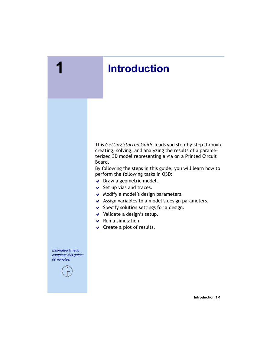
1
Introduction
This Getting Started Guide leads you step-by-step through
creating, solving, and analyzing the results of a parame-
terized 3D model representing a via on a Printed Circuit
Board.
By following the steps in this guide, you will learn how to
perform the following tasks in Q3D:
Draw a geometric model.
Set up vias and traces.
Modify a model’s design parameters.
Assign variables to a model’s design parameters.
Specify solution settings for a design.
Validate a design’s setup.
Run a simulation.
Create a plot of results.
Estimated time to
complete this guide:
60 minutes.
Introduction 1-1
�



 2023年江西萍乡中考道德与法治真题及答案.doc
 2012年重庆南川中考生物真题及答案.doc
 2013年江西师范大学地理学综合及文艺理论基础考研真题.doc
 2020年四川甘孜小升初语文真题及答案I卷.doc
 2020年注册岩土工程师专业基础考试真题及答案.doc
 2023-2024学年福建省厦门市九年级上学期数学月考试题及答案.doc
 2021-2022学年辽宁省沈阳市大东区九年级上学期语文期末试题及答案.doc
 2022-2023学年北京东城区初三第一学期物理期末试卷及答案.doc
 2018上半年江西教师资格初中地理学科知识与教学能力真题及答案.doc
 2012年河北国家公务员申论考试真题及答案-省级.doc
 2020-2021学年江苏省扬州市江都区邵樊片九年级上学期数学第一次质量检测试题及答案.doc
 2022下半年黑龙江教师资格证中学综合素质真题及答案.doc