logo资料库

锁相环转速估计.pdf

第1页 / 共52页
第2页 / 共52页
第3页 / 共52页
第4页 / 共52页
第5页 / 共52页
第6页 / 共52页
第7页 / 共52页
第8页 / 共52页
资料共52页,剩余部分请下载后查看
Estimating Rotational Speed with a Phase-Locked Loop
Abstract
1. Introduction
2. The current method for measuring rotational speed
2.1. The inductive sensor
2.2. From sensor output to velocity estimation
2.2.1. Filtering and signal adaptation
2.2.2. Time delays caused by filtering and signal adaptation
2.2.3. The interrupt routine
2.2.4. Algorithms used in the ECU
3. The Sensor Output
4. Phase-locked loops – Theory
4.1. Basic working principles of a PLL
4.2. Mathematical derivation of a first order PLL
4.3. The second order PLL
4.4. Previous use of PLL’s in the automotive industry
4.5. How can a PLL improve our measurements of rotational speed?
4.6. The gradient descent method for design of a more complete PLL
4.6.1. The algorithm
4.6.2. Simulations
4.7. The quadrature phase-locked loop (QPLL)
4.7.1. The algorithm
5. Implementation of a PLL in hardware
5.1. Necessary components
5.1.1. The phase detector
5.1.2. The voltage controlled oscillator (VCO)
5.1.3. The PI-controller/Loop filter
5.2. The LM565C Phase-locked loop integrated circuit
5.2.1. Limitations and tuning
5.2.2. Comments
6. The QPLL – Machine testing
6.1. Previous results
6.2. Signal processing
6.2.1. The current ECU estimation
6.2.2. The QPLL estimation
6.3. Results from machine testing
6.3.1. A hard brake
6.3.2. A Hard brake and change of direction
6.3.3. Periodic change in velocity
6.3.4. A constant very low velocity
7. The PLL in hardware – Results from a test bench
7.1. The test bench
7.2. Signal processing
7.2.1. The current ECU estimation
7.2.2. The PLL in hardware
7.2.3. The Encoder estimate
7.3. Results from the test bench
7.3.1. Periodic change in velocity
7.3.2. Step changes in velocity
7.3.3. Testing the limits
7.4. Robustness
8. Discussion and conclusion
8.1. The QPLL
8.2. The hardware-PLL
8.3. Other possible improvements
9. Future work
10. Bibliography
10.1. Scientific papers
10.2. Web pages
Estimating Rotational Speed with a Phase- Locked Loop NIKLAS WILLEMSEN Masters’ Degree Project Stockholm, Sweden June 2008 XR-EE-RT 2008:015
2
Abstract Volvo Construction Equipment Components AB (Volvo CE) develops electronic control systems for various vehicles in the field of construction equipment. Increasing demands on quality, safety and environmental care require more and more sophisticated and intelligent drive control systems. These new systems are dependant on high quality input data from various sensors. One of these sensors is of inductive type and is used for measuring rotational speed of a gear wheel, and the method of doing this is the subject of this thesis. The current method applied at Volvo CE for measuring this speed needs to be changed in order to cope with these new demands, especially at low velocities. The alternative method presented in this paper is based on Phase-locked loop (PLL) techniques, which is a closed loop frequency control system. In this thesis two different ways of implementing a PLL are investigated; a Quadrature phase- locked loop (QPLL) in software and a second order PLL in hardware. The QPLL is derived through optimization theory and implemented in Simulink. The second order PLL is the integrated circuit LM565 from the manufacturer National Semiconductor. The QPLL is tested in a wheel loader and compared with the current method used at Volvo CE today. The results show that in the general case the QPLL is not better than the current method but at fast retardations and when changes of the velocity directions occur the QPLL outperforms the current method. A drawback with the QPLL is its behaviour at constant low velocities where it tends to lose track of the signal. The hardware-PLL is tested in a test bench with similar working conditions as in a machine. The results show that this method has a limited frequency interval but in this interval the performance is as good as the current method and very robust. The conclusion of this thesis is that PLL methods are interesting and could improve the quality of the measurements when the velocity is changing very fast but in the general case the current method is just as good. Implementing a PLL would require some extra expenses in terms of additional hardware but with the results presented in this thesis it does not seem cost effective. 3
4
2.1. 2.2. 5. 4.6.1. 4.6.2. 4.7. 2.2.1. 2.2.2. 2.2.3. 2.2.4. Index 1. Introduction ___________________________________________________________ 7 2. The current method for measuring rotational speed__________________________ 8 The inductive sensor................................................................................................... 8 From sensor output to velocity estimation ................................................................. 9 Filtering and signal adaptation ........................................................................... 9 Time delays caused by filtering and signal adaptation .................................... 11 The interrupt routine......................................................................................... 11 Algorithms used in the ECU ............................................................................ 11 3. The Sensor Output ____________________________________________________ 13 4. Phase-locked loops – Theory ____________________________________________ 16 4.1. Basic working principles of a PLL........................................................................... 16 4.2. Mathematical derivation of a first order PLL........................................................... 16 The second order PLL.............................................................................................. 17 4.3. 4.4. Previous use of PLL’s in the automotive industry ................................................... 20 4.5. How can a PLL improve our measurements of rotational speed?............................ 21 The gradient descent method for design of a more complete PLL .......................... 21 4.6. The algorithm ................................................................................................... 21 Simulations....................................................................................................... 23 The quadrature phase-locked loop (QPLL).............................................................. 27 4.7.1. The algorithm ................................................................................................... 27 Implementation of a PLL in hardware ____________________________________ 30 5.1. Necessary components ............................................................................................. 30 The phase detector............................................................................................ 30 The voltage controlled oscillator (VCO).......................................................... 30 The PI-controller/Loop filter............................................................................ 31 The LM565C Phase-locked loop integrated circuit ................................................. 31 Limitations and tuning ..................................................................................... 32 Comments......................................................................................................... 33 6. The QPLL – Machine testing ____________________________________________ 34 Previous results ........................................................................................................ 34 Signal processing...................................................................................................... 34 The current ECU estimation............................................................................. 34 The QPLL estimation....................................................................................... 34 6.3. Results from machine testing ................................................................................... 34 A hard brake..................................................................................................... 34 A Hard brake and change of direction ............................................................. 36 Periodic change in velocity .............................................................................. 40 A constant very low velocity............................................................................ 41 7. The PLL in hardware – Results from a test bench __________________________ 42 The test bench........................................................................................................... 42 Signal processing...................................................................................................... 43 The current ECU estimation............................................................................. 43 The PLL in hardware........................................................................................ 43 The Encoder estimate....................................................................................... 43 7.3. Results from the test bench ...................................................................................... 43 Periodic change in velocity .............................................................................. 43 Step changes in velocity................................................................................... 44 Testing the limits.............................................................................................. 45 7.4. Robustness................................................................................................................ 47 8. Discussion and conclusion ______________________________________________ 49 7.3.1. 7.3.2. 7.3.3. 6.2.1. 6.2.2. 6.3.1. 6.3.2. 6.3.3. 6.3.4. 5.1.1. 5.1.2. 5.1.3. 5.2.1. 5.2.2. 5.2. 6.1. 6.2. 7.1. 7.2. 7.2.1. 7.2.2. 7.2.3. 5
The QPLL................................................................................................................. 49 8.1. 8.2. The hardware-PLL ................................................................................................... 49 8.3. Other possible improvements................................................................................... 50 9. Future work __________________________________________________________ 51 10. Bibliography _________________________________________________________ 52 10.1. Scientific papers ............................................................................................... 52 10.2. Web pages ........................................................................................................ 52 6
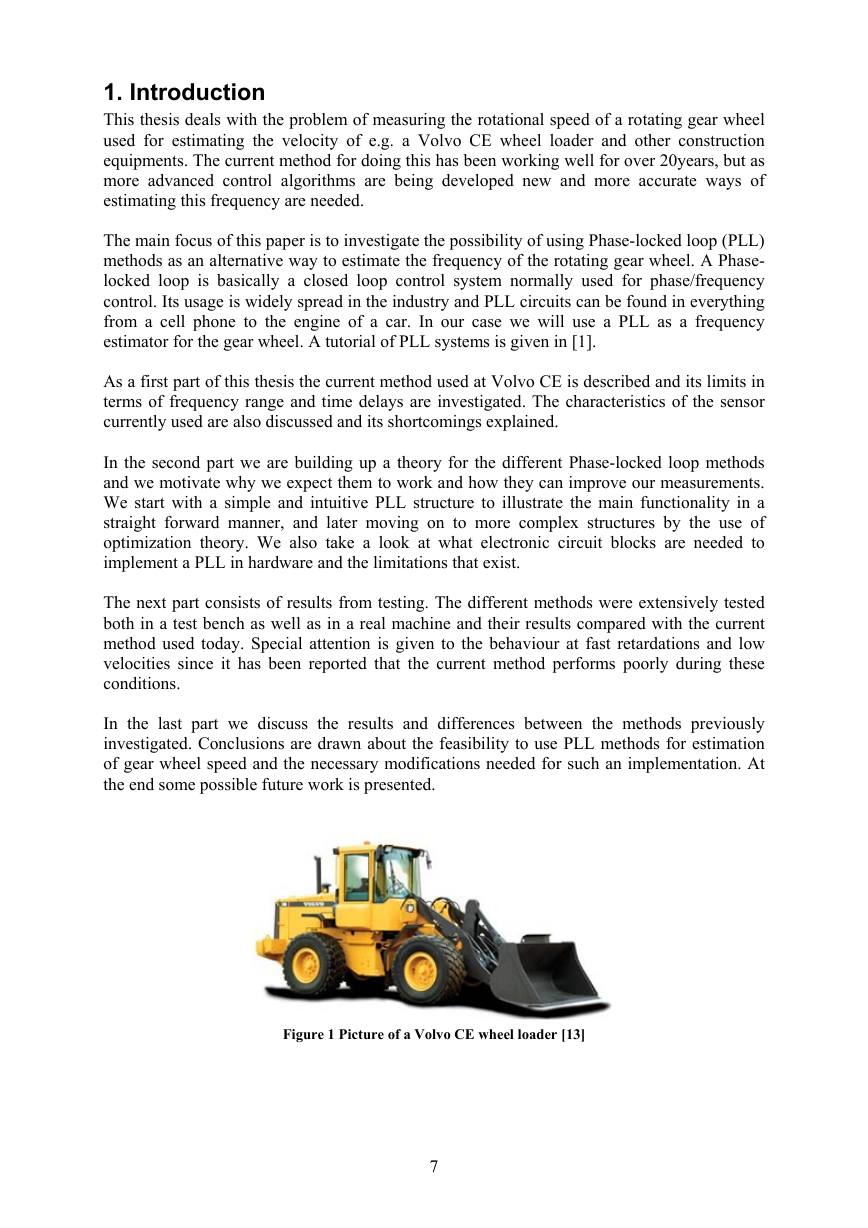
1. Introduction This thesis deals with the problem of measuring the rotational speed of a rotating gear wheel used for estimating the velocity of e.g. a Volvo CE wheel loader and other construction equipments. The current method for doing this has been working well for over 20years, but as more advanced control algorithms are being developed new and more accurate ways of estimating this frequency are needed. The main focus of this paper is to investigate the possibility of using Phase-locked loop (PLL) methods as an alternative way to estimate the frequency of the rotating gear wheel. A Phase- locked loop is basically a closed loop control system normally used for phase/frequency control. Its usage is widely spread in the industry and PLL circuits can be found in everything from a cell phone to the engine of a car. In our case we will use a PLL as a frequency estimator for the gear wheel. A tutorial of PLL systems is given in [1]. As a first part of this thesis the current method used at Volvo CE is described and its limits in terms of frequency range and time delays are investigated. The characteristics of the sensor currently used are also discussed and its shortcomings explained. In the second part we are building up a theory for the different Phase-locked loop methods and we motivate why we expect them to work and how they can improve our measurements. We start with a simple and intuitive PLL structure to illustrate the main functionality in a straight forward manner, and later moving on to more complex structures by the use of optimization theory. We also take a look at what electronic circuit blocks are needed to implement a PLL in hardware and the limitations that exist. The next part consists of results from testing. The different methods were extensively tested both in a test bench as well as in a real machine and their results compared with the current method used today. Special attention is given to the behaviour at fast retardations and low velocities since it has been reported that the current method performs poorly during these conditions. In the last part we discuss the results and differences between the methods previously investigated. Conclusions are drawn about the feasibility to use PLL methods for estimation of gear wheel speed and the necessary modifications needed for such an implementation. At the end some possible future work is presented. Figure 1 Picture of a Volvo CE wheel loader [13] 7
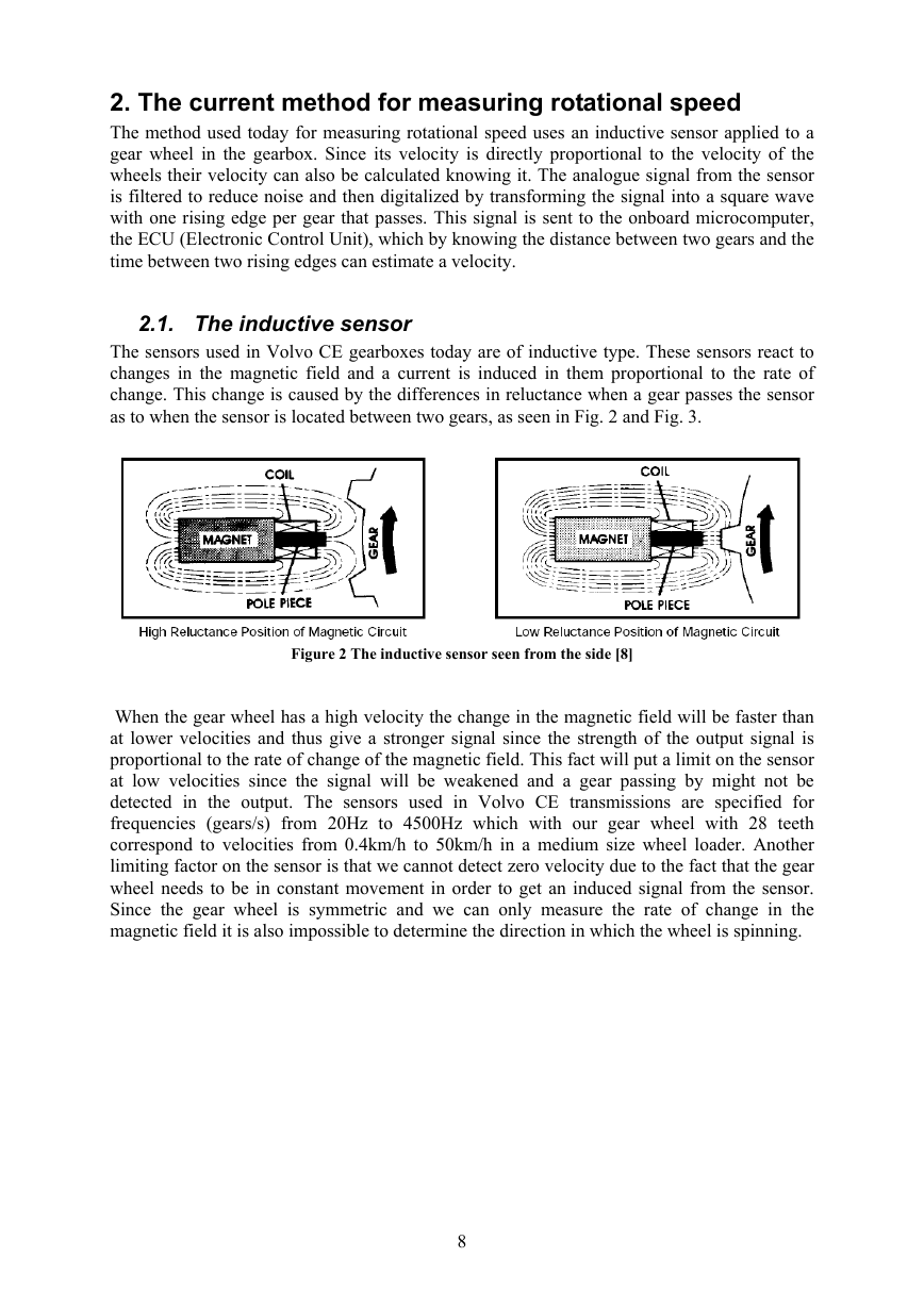
2. The current method for measuring rotational speed The method used today for measuring rotational speed uses an inductive sensor applied to a gear wheel in the gearbox. Since its velocity is directly proportional to the velocity of the wheels their velocity can also be calculated knowing it. The analogue signal from the sensor is filtered to reduce noise and then digitalized by transforming the signal into a square wave with one rising edge per gear that passes. This signal is sent to the onboard microcomputer, the ECU (Electronic Control Unit), which by knowing the distance between two gears and the time between two rising edges can estimate a velocity. 2.1. The inductive sensor The sensors used in Volvo CE gearboxes today are of inductive type. These sensors react to changes in the magnetic field and a current is induced in them proportional to the rate of change. This change is caused by the differences in reluctance when a gear passes the sensor as to when the sensor is located between two gears, as seen in Fig. 2 and Fig. 3. Figure 2 The inductive sensor seen from the side [8] When the gear wheel has a high velocity the change in the magnetic field will be faster than at lower velocities and thus give a stronger signal since the strength of the output signal is proportional to the rate of change of the magnetic field. This fact will put a limit on the sensor at low velocities since the signal will be weakened and a gear passing by might not be detected in the output. The sensors used in Volvo CE transmissions are specified for frequencies (gears/s) from 20Hz to 4500Hz which with our gear wheel with 28 teeth correspond to velocities from 0.4km/h to 50km/h in a medium size wheel loader. Another limiting factor on the sensor is that we cannot detect zero velocity due to the fact that the gear wheel needs to be in constant movement in order to get an induced signal from the sensor. Since the gear wheel is symmetric and we can only measure the rate of change in the magnetic field it is also impossible to determine the direction in which the wheel is spinning. 8
分享到:
收藏