logo资料库

GC9307数据手册.pdf

第1页 / 共190页
第2页 / 共190页
第3页 / 共190页
第4页 / 共190页
第5页 / 共190页
第6页 / 共190页
第7页 / 共190页
第8页 / 共190页
资料共190页,剩余部分请下载后查看
GC9307
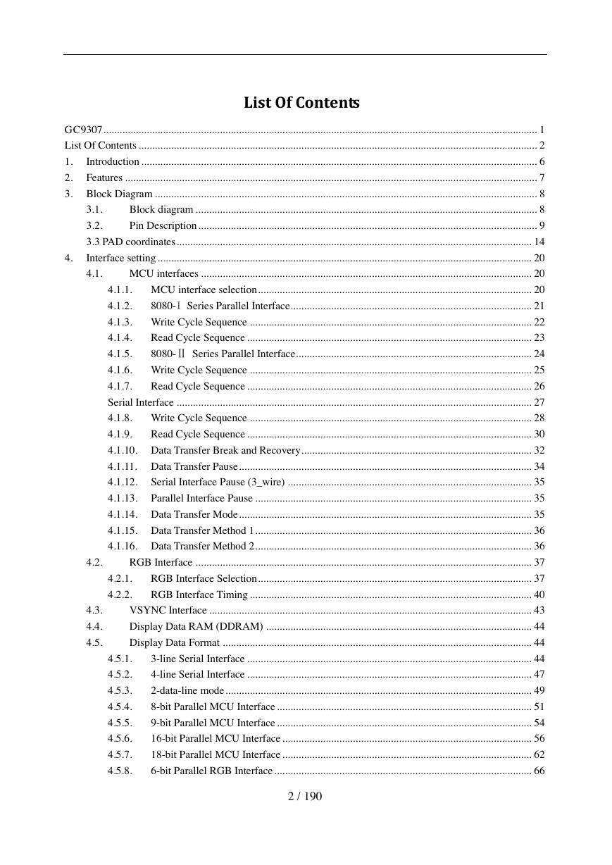
List Of Contents
1. Introduction
2. Features
3. Block Diagram
3.1. Block diagram
3.2. Pin Description
3.3 PAD coordinates
4. Interface setting
4.1. MCU interfaces
4.1.1. MCU interface selection
4.1.2. 8080-I Series Parallel Interface
4.1.3. Write Cycle Sequence
4.1.4. Read Cycle Sequence
4.1.5. 8080-Ⅱ Series Parallel Interface
4.1.6. Write Cycle Sequence
4.1.7. Read Cycle Sequence
Serial Interface
4.1.8. Write Cycle Sequence
4.1.9. Read Cycle Sequence
4.1.10. Data Transfer Break and Recovery
4.1.11. Data Transfer Pause
4.1.12. Serial Interface Pause (3_wire)
4.1.13. Parallel Interface Pause
4.1.14. Data Transfer Mode
4.1.15. Data Transfer Method 1
4.1.16. Data Transfer Method 2
4.2. RGB Interface
4.2.1. RGB Interface Selection
4.2.2. RGB Interface Timing
4.3. VSYNC Interface
4.4. Display Data RAM (DDRAM)
4.5. Display Data Format
4.5.1. 3-line Serial Interface
4.5.2. 4-line Serial Interface
4.5.3. 2-data-line mode
4.5.4. 8-bit Parallel MCU Interface
4.5.5. 9-bit Parallel MCU Interface
4.5.6. 16-bit Parallel MCU Interface
4.5.7. 18-bit Parallel MCU Interface
4.5.8. 6-bit Parallel RGB Interface
4.5.9. 16-bit Parallel RGB Interface
4.5.10. 18-bit Parallel RGB Interface
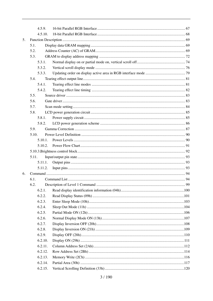
5. Function Description
5.1. Display data GRAM mapping
5.2. Address Counter (AC) of GRAM
5.3. GRAM to display address mapping
5.3.1. Normal display on or partial mode on, vertical scroll off
5.3.2. Vertical scroll display mode
5.3.3. Updating order on display active area in RGB interface mode
5.4. Tearing effect output line
5.4.1. Tearing effect line modes
5.4.2. Tearing effect line timing
5.5. Source driver
5.6. Gate driver
5.7. Scan mode setting
5.8. LCD power generation circuit
5.8.1. Power supply circuit
5.8.2. LCD power generation scheme
5.9. Gamma Correction
5.10. Power Level Definition
5.10.1. Power Levels
5.10.2. Power Flow Chart
5.10.3.Brightness control block
5.11. Input/output pin state
5.11.1. Output pins
5.11.2. Input pins
6. Command
6.1. Command List
6.2. Description of Level 1 Command
6.2.1. Read display identification information (04h)
6.2.2. Read Display Status (09h)
6.2.3. Enter Sleep Mode (10h)
6.2.4. Sleep Out Mode (11h)
6.2.5. Partial Mode ON (12h)
6.2.6. Normal Display Mode ON (13h)
6.2.7. Display Inversion OFF (20h)
6.2.8. Display Inversion ON (21h)
6.2.9. Display OFF (28h)
6.2.10. Display ON (29h)
6.2.11. Column Address Set (2Ah)
6.2.12. Row Address Set (2Bh)
6.2.13. Memory Write (2Ch)
6.2.14. Partial Area (30h)
6.2.15. Vertical Scrolling Definition (33h)
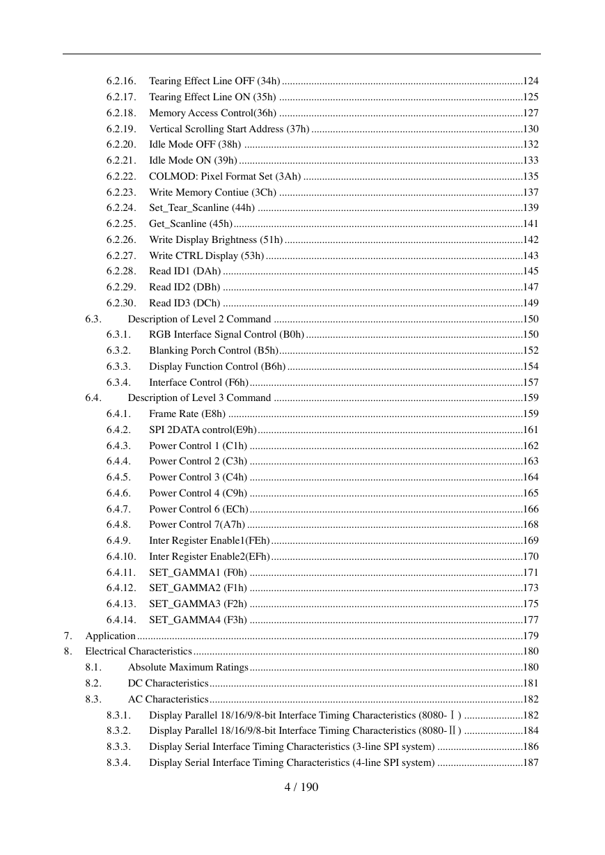
6.2.16. Tearing Effect Line OFF (34h)
6.2.17. Tearing Effect Line ON (35h)
6.2.18. Memory Access Control(36h)
6.2.19. Vertical Scrolling Start Address (37h)
6.2.20. Idle Mode OFF (38h)
6.2.21. Idle Mode ON (39h)
6.2.22. COLMOD: Pixel Format Set (3Ah)
6.2.23. Write Memory Contiue (3Ch)
6.2.24. Set_Tear_Scanline (44h)
6.2.25. Get_Scanline (45h)
6.2.26. Write Display Brightness (51h)
6.2.27. Write CTRL Display (53h)
6.2.28. Read ID1 (DAh)
6.2.29. Read ID2 (DBh)
6.2.30. Read ID3 (DCh)
6.3. Description of Level 2 Command
6.3.1. RGB Interface Signal Control (B0h)
6.3.2. Blanking Porch Control (B5h)
6.3.3. Display Function Control (B6h)
6.3.4. Interface Control (F6h)
6.4. Description of Level 3 Command
6.4.1. Frame Rate (E8h)
6.4.2. SPI 2DATA control(E9h)
6.4.3. Power Control 1 (C1h)
6.4.4. Power Control 2 (C3h)
6.4.5. Power Control 3 (C4h)
6.4.6. Power Control 4 (C9h)
6.4.7. Power Control 6 (ECh)
6.4.8. Power Control 7(A7h)
6.4.9. Inter Register Enable1(FEh)
6.4.10. Inter Register Enable2(EFh)
6.4.11. SET_GAMMA1 (F0h)
6.4.12. SET_GAMMA2 (F1h)
6.4.13. SET_GAMMA3 (F2h)
6.4.14. SET_GAMMA4 (F3h)
7. Application
8. Electrical Characteristics
8.1. Absolute Maximum Ratings
8.2. DC Characteristics
8.3. AC Characteristics
8.3.1. Display Parallel 18/16/9/8-bit Interface Timing Characteristics (8080-Ⅰ)
8.3.2. Display Parallel 18/16/9/8-bit Interface Timing Characteristics (8080-Ⅱ)
8.3.3. Display Serial Interface Timing Characteristics (3-line SPI system)
8.3.4. Display Serial Interface Timing Characteristics (4-line SPI system)
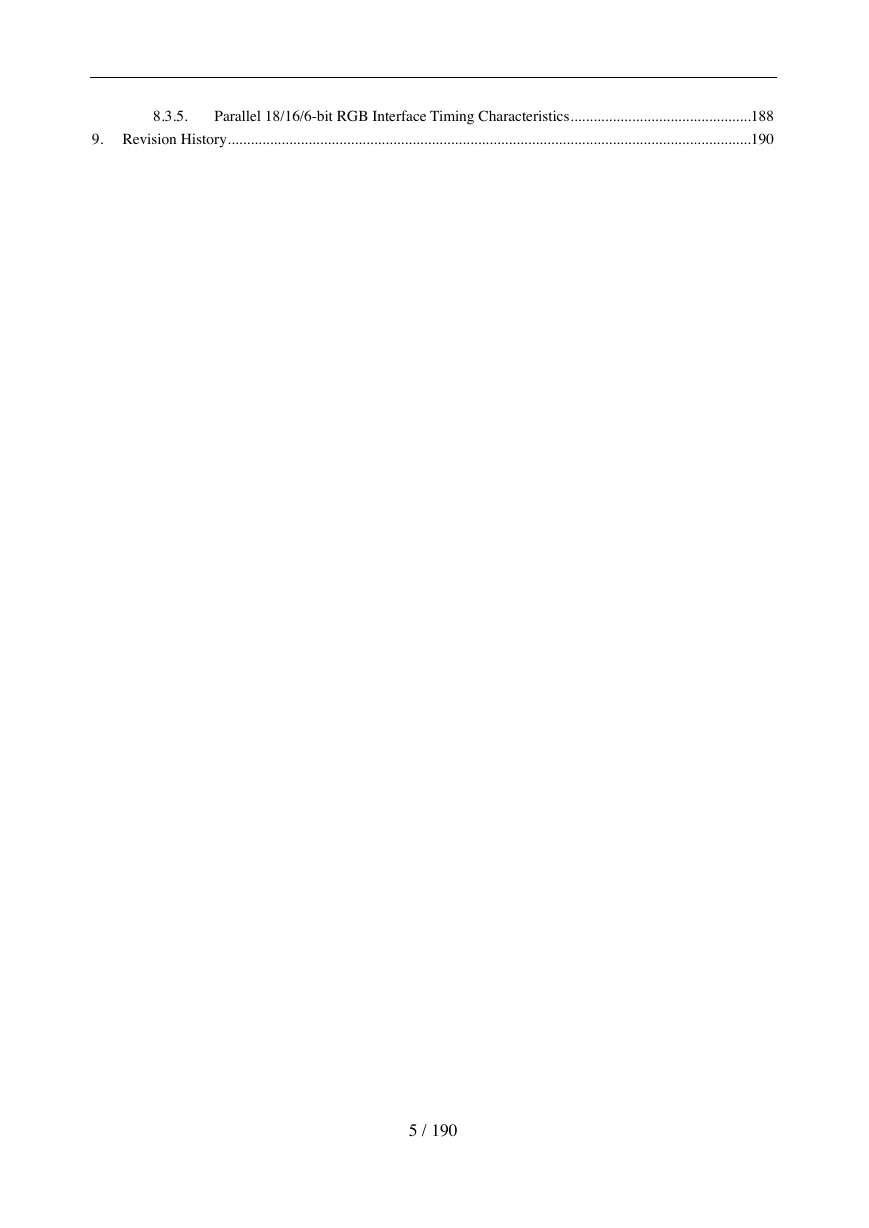
8.3.5. Parallel 18/16/6-bit RGB Interface Timing Characteristics
9. Revision History
GC9307 a-Si TFT LCD Single Chip Driver 240RGBx320 Resolution and 262K color DataSheet Version: V1.01 Created Date: 2018/04/24 1 / 190
List Of Contents GC9307 ................................................................................................................................................................ 1 List Of Contents ................................................................................................................................................... 2 1. Introduction .................................................................................................................................................. 6 2. Features ........................................................................................................................................................ 7 3. Block Diagram ............................................................................................................................................. 8 Block diagram .............................................................................................................................. 8 3.1. 3.2. Pin Description ............................................................................................................................. 9 3.3 PAD coordinates ................................................................................................................................... 14 Interface setting .......................................................................................................................................... 20 MCU interfaces .......................................................................................................................... 20 4.1. 4.1.1. MCU interface selection ..................................................................................................... 20 8080-I Series Parallel Interface ......................................................................................... 21 4.1.2. 4.1.3. Write Cycle Sequence ........................................................................................................ 22 4.1.4. Read Cycle Sequence ......................................................................................................... 23 8080-Ⅱ Series Parallel Interface ....................................................................................... 24 4.1.5. 4.1.6. Write Cycle Sequence ........................................................................................................ 25 4.1.7. Read Cycle Sequence ......................................................................................................... 26 Serial Interface ................................................................................................................................... 27 4.1.8. Write Cycle Sequence ........................................................................................................ 28 4.1.9. Read Cycle Sequence ......................................................................................................... 30 4.1.10. Data Transfer Break and Recovery ..................................................................................... 32 4.1.11. Data Transfer Pause ............................................................................................................ 34 4.1.12. Serial Interface Pause (3_wire) .......................................................................................... 35 4.1.13. Parallel Interface Pause ...................................................................................................... 35 4.1.14. Data Transfer Mode ............................................................................................................ 35 4.1.15. Data Transfer Method 1 ...................................................................................................... 36 4.1.16. Data Transfer Method 2 ...................................................................................................... 36 RGB Interface ............................................................................................................................ 37 RGB Interface Selection ..................................................................................................... 37 RGB Interface Timing ........................................................................................................ 40 VSYNC Interface ....................................................................................................................... 43 Display Data RAM (DDRAM) .................................................................................................. 44 Display Data Format .................................................................................................................. 44 3-line Serial Interface ......................................................................................................... 44 4-line Serial Interface ......................................................................................................... 47 2-data-line mode ................................................................................................................. 49 8-bit Parallel MCU Interface .............................................................................................. 51 9-bit Parallel MCU Interface .............................................................................................. 54 16-bit Parallel MCU Interface ............................................................................................ 56 18-bit Parallel MCU Interface ............................................................................................ 62 6-bit Parallel RGB Interface ............................................................................................... 66 4.5.1. 4.5.2. 4.5.3. 4.5.4. 4.5.5. 4.5.6. 4.5.7. 4.5.8. 4.2.1. 4.2.2. 4. 4.2. 4.3. 4.4. 4.5. 2 / 190
5.1. 5.2. 5.3. 5.4. 5.5. 5.6. 5.7. 5.8. 5.4.1. 5.4.2. 4.5.9. 4.5.10. 5.3.1. 5.3.2. 5.3.3. 16-bit Parallel RGB Interface ............................................................................................. 67 18-bit Parallel RGB Interface ............................................................................................. 68 5. Function Description .................................................................................................................................. 69 Display data GRAM mapping .................................................................................................... 69 Address Counter (AC) of GRAM ............................................................................................... 69 GRAM to display address mapping ........................................................................................... 72 Normal display on or partial mode on, vertical scroll off ................................................... 74 Vertical scroll display mode ............................................................................................... 76 Updating order on display active area in RGB interface mode .......................................... 79 Tearing effect output line ............................................................................................................ 81 Tearing effect line modes ................................................................................................... 81 Tearing effect line timing ................................................................................................... 82 Source driver .............................................................................................................................. 83 Gate driver .................................................................................................................................. 83 Scan mode setting ....................................................................................................................... 84 LCD power generation circuit .................................................................................................... 85 Power supply circuit ........................................................................................................... 85 LCD power generation scheme .......................................................................................... 86 Gamma Correction ..................................................................................................................... 87 Power Level Definition .............................................................................................................. 90 5.10.1. Power Levels ...................................................................................................................... 90 5.10.2. Power Flow Chart ............................................................................................................... 91 5.10.3.Brightness control block .................................................................................................................. 92 Input/output pin state .................................................................................................................. 93 5.11. 5.11.1. Output pins ......................................................................................................................... 93 5.11.2. Input pins ............................................................................................................................ 93 6. Command ................................................................................................................................................... 94 Command List ............................................................................................................................ 94 Description of Level 1 Command .............................................................................................. 99 Read display identification information (04h) ...................................................................100 6.2.1. Read Display Status (09h) .................................................................................................101 6.2.2. Enter Sleep Mode (10h).....................................................................................................103 6.2.3. Sleep Out Mode (11h) .......................................................................................................104 6.2.4. Partial Mode ON (12h) ......................................................................................................106 6.2.5. Normal Display Mode ON (13h) .......................................................................................107 6.2.6. Display Inversion OFF (20h) .............................................................................................108 6.2.7. Display Inversion ON (21h) ..............................................................................................109 6.2.8. 6.2.9. Display OFF (28h) ............................................................................................................. 110 6.2.10. Display ON (29h) .............................................................................................................. 111 6.2.11. Column Address Set (2Ah) ................................................................................................ 112 6.2.12. Row Address Set (2Bh) ..................................................................................................... 114 6.2.13. Memory Write (2Ch) ......................................................................................................... 116 6.2.14. Partial Area (30h) .............................................................................................................. 117 6.2.15. Vertical Scrolling Definition (33h) ....................................................................................120 5.8.1. 5.8.2. 5.9. 5.10. 6.1. 6.2. 3 / 190
6.3.1. 6.3.2. 6.3.3. 6.3.4. 6.2.16. Tearing Effect Line OFF (34h) ..........................................................................................124 6.2.17. Tearing Effect Line ON (35h) ...........................................................................................125 6.2.18. Memory Access Control(36h) ...........................................................................................127 6.2.19. Vertical Scrolling Start Address (37h) ...............................................................................130 Idle Mode OFF (38h) ........................................................................................................132 6.2.20. 6.2.21. Idle Mode ON (39h) ..........................................................................................................133 6.2.22. COLMOD: Pixel Format Set (3Ah) ..................................................................................135 6.2.23. Write Memory Contiue (3Ch) ...........................................................................................137 6.2.24. Set_Tear_Scanline (44h) ...................................................................................................139 6.2.25. Get_Scanline (45h) ............................................................................................................141 6.2.26. Write Display Brightness (51h) .........................................................................................142 6.2.27. Write CTRL Display (53h) ................................................................................................143 6.2.28. Read ID1 (DAh) ................................................................................................................145 6.2.29. Read ID2 (DBh) ................................................................................................................147 6.2.30. Read ID3 (DCh) ................................................................................................................149 Description of Level 2 Command .............................................................................................150 RGB Interface Signal Control (B0h) .................................................................................150 Blanking Porch Control (B5h) ...........................................................................................152 Display Function Control (B6h) ........................................................................................154 Interface Control (F6h) ......................................................................................................157 Description of Level 3 Command .............................................................................................159 Frame Rate (E8h) ..............................................................................................................159 6.4.1. SPI 2DATA control(E9h) ...................................................................................................161 6.4.2. Power Control 1 (C1h) ......................................................................................................162 6.4.3. Power Control 2 (C3h) ......................................................................................................163 6.4.4. Power Control 3 (C4h) ......................................................................................................164 6.4.5. Power Control 4 (C9h) ......................................................................................................165 6.4.6. Power Control 6 (ECh) ......................................................................................................166 6.4.7. Power Control 7(A7h) .......................................................................................................168 6.4.8. Inter Register Enable1(FEh) ..............................................................................................169 6.4.9. 6.4.10. Inter Register Enable2(EFh) ..............................................................................................170 6.4.11. SET_GAMMA1 (F0h) ......................................................................................................171 6.4.12. SET_GAMMA2 (F1h) ......................................................................................................173 6.4.13. SET_GAMMA3 (F2h) ......................................................................................................175 6.4.14. SET_GAMMA4 (F3h) ......................................................................................................177 7. Application ................................................................................................................................................179 8. Electrical Characteristics ...........................................................................................................................180 Absolute Maximum Ratings ......................................................................................................180 DC Characteristics .....................................................................................................................181 AC Characteristics .....................................................................................................................182 Display Parallel 18/16/9/8-bit Interface Timing Characteristics (8080-Ⅰ) ......................182 Display Parallel 18/16/9/8-bit Interface Timing Characteristics (8080-Ⅱ) ......................184 Display Serial Interface Timing Characteristics (3-line SPI system) ................................186 Display Serial Interface Timing Characteristics (4-line SPI system) ................................187 8.3.1. 8.3.2. 8.3.3. 8.3.4. 6.3. 6.4. 8.1. 8.2. 8.3. 4 / 190
8.3.5. Parallel 18/16/6-bit RGB Interface Timing Characteristics ...............................................188 9. Revision History ........................................................................................................................................190 5 / 190
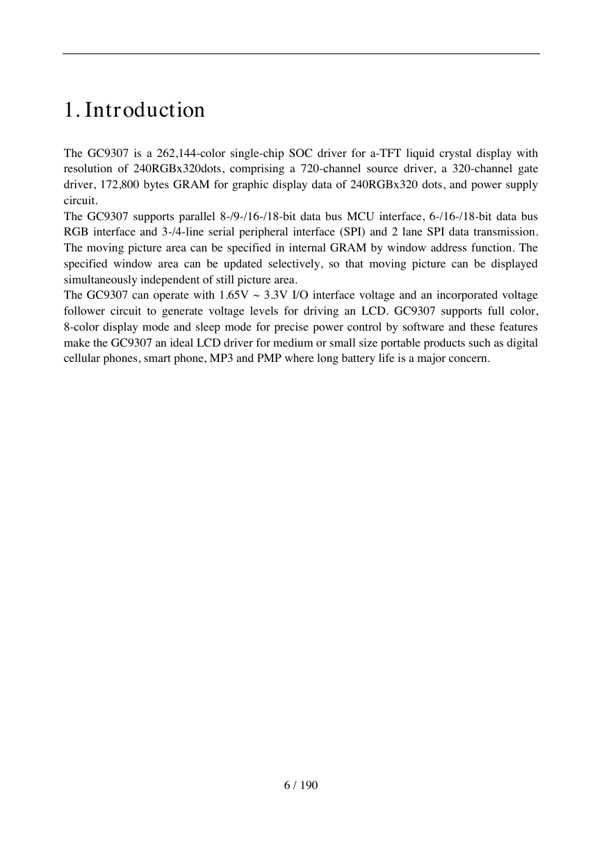
1. Introduction The GC9307 is a 262,144-color single-chip SOC driver for a-TFT liquid crystal display with resolution of 240RGBx320dots, comprising a 720-channel source driver, a 320-channel gate driver, 172,800 bytes GRAM for graphic display data of 240RGBx320 dots, and power supply circuit. The GC9307 supports parallel 8-/9-/16-/18-bit data bus MCU interface, 6-/16-/18-bit data bus RGB interface and 3-/4-line serial peripheral interface (SPI) and 2 lane SPI data transmission. The moving picture area can be specified in internal GRAM by window address function. The specified window area can be updated selectively, so that moving picture can be displayed simultaneously independent of still picture area. The GC9307 can operate with 1.65V ~ 3.3V I/O interface voltage and an incorporated voltage follower circuit to generate voltage levels for driving an LCD. GC9307 supports full color, 8-color display mode and sleep mode for precise power control by software and these features make the GC9307 an ideal LCD driver for medium or small size portable products such as digital cellular phones, smart phone, MP3 and PMP where long battery life is a major concern. 6 / 190
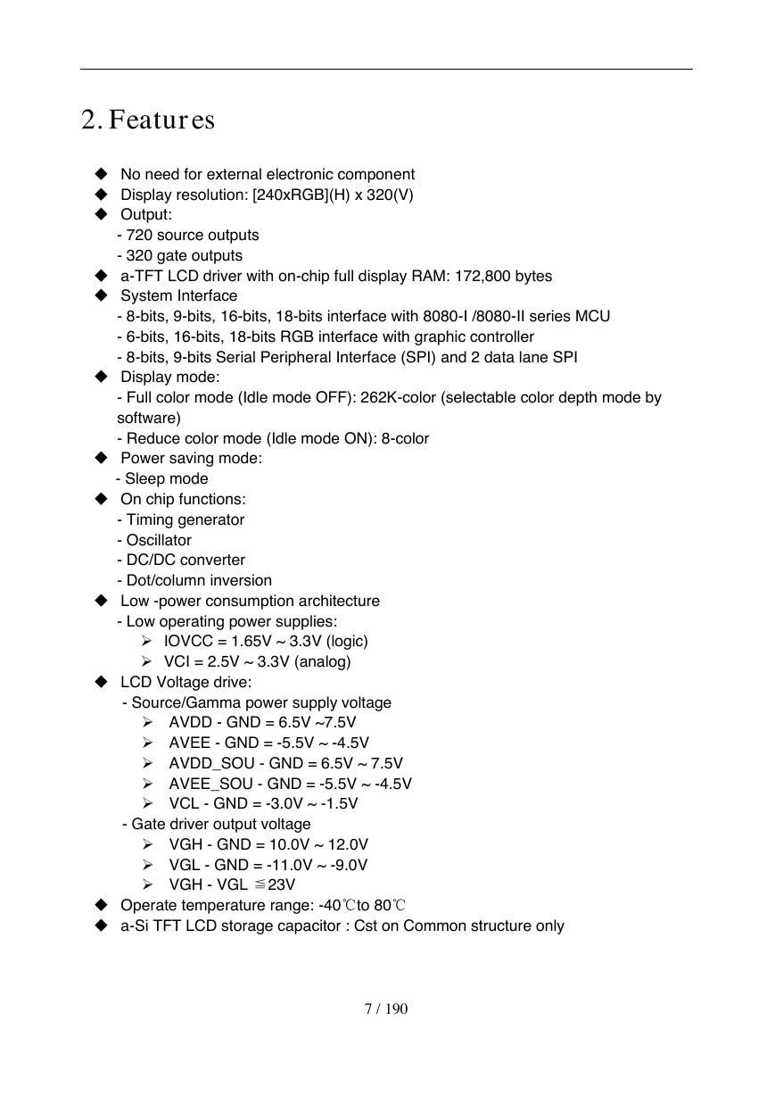
2. Features  No need for external electronic component  Display resolution: [240xRGB](H) x 320(V)  Output: - 720 source outputs - 320 gate outputs  a-TFT LCD driver with on-chip full display RAM: 172,800 bytes  System Interface - 8-bits, 9-bits, 16-bits, 18-bits interface with 8080-I /8080-II series MCU - 6-bits, 16-bits, 18-bits RGB interface with graphic controller - 8-bits, 9-bits Serial Peripheral Interface (SPI) and 2 data lane SPI  Display mode: - Full color mode (Idle mode OFF): 262K-color (selectable color depth mode by software) - Reduce color mode (Idle mode ON): 8-color  Power saving mode: - Sleep mode  On chip functions: - Timing generator - Oscillator - DC/DC converter - Dot/column inversion  Low -power consumption architecture - Low operating power supplies:  IOVCC = 1.65V ~ 3.3V (logic)  VCI = 2.5V ~ 3.3V (analog)  LCD Voltage drive: - Source/Gamma power supply voltage  AVDD - GND = 6.5V ~7.5V  AVEE - GND = -5.5V ~ -4.5V  AVDD_SOU - GND = 6.5V ~ 7.5V  AVEE_SOU - GND = -5.5V ~ -4.5V  VCL - GND = -3.0V ~ -1.5V - Gate driver output voltage  VGH - GND = 10.0V ~ 12.0V  VGL - GND = -11.0V ~ -9.0V  VGH - VGL ≦23V  Operate temperature range: -40℃to 80℃  a-Si TFT LCD storage capacitor : Cst on Common structure only 7 / 190
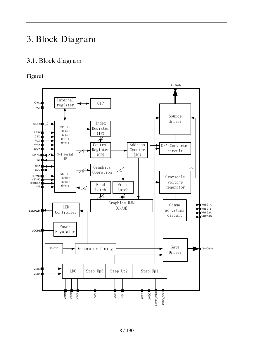
3. Block Diagram 3.1. Block diagram Figure1 8 / 190 MPU IF18-bit16-bit8-bit9-bit3/4 Serial IFRGB IF18-bit16-bit6-bitVCIIOVCCIM[3:0]4Internal registerOTPCSXRDXWRXD/CXRESXD[17:0]18TESDASDOHSYNCVSYNCDOTCLKDEPower RegulatorVCOREGenerator TimingVSSCVSSAStep Up1Step Up2Step Up3AVDDVGHVGLVCLGate DriverG1~G320LEDControllerLEDPWMIndexRegister(IR)ControlRegister(CR)GraphicsOperationRead Latch881818Graphics RAM(GRAM)18Write Latch1818AddressCounter(AC)Gamma adjusting circuitGrayscale voltage generatorD/A Converter circuitSourcedriverS1~S720V0~63RC-OSCAVEEVREG1AVREG1BVREG2AVREG2BLDOVRDDVREEVRCLAVDD_SOUAVEE_SOU
分享到:
收藏