SD Specifications
Part E1
SDIO Specification
Version 2.00
January 30, 2007
Technical Committee
SD Card Association
ChrontelDownloaded by Roger Yu Chrontel on 06/18/2008�
SDIO Specification Version 2.00
©Copyright 2000-2007 SD Card Association
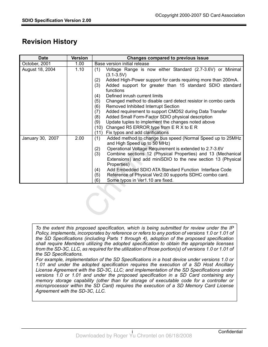
Revision History
Date
October, 2001
August 18, 2004
Version
1.00
1.10
January 30, 2007
2.00
Changes compared to previous issue
Base version initial release
(1) Voltage Range is now either Standard (2.7-3.6V) or Minimal
(2) Added High-Power support for cards requiring more than 200mA.
(3) Added support for greater than 15 standard SDIO standard
(3.1-3.5V)
functions
(4) Defined inrush current limits
(5) Changed method to disable card detect resistor in combo cards
(6) Removed Inhibited Interrupt Section
(7) Added requirement to support CMD52 during Data Transfer
(8) Added Small Form-Factor SDIO physical description
(9) Update tuples to implement the changes noted above
(10) Changed R5 ERROR type from E R X to E R
(11) Fix typos and add clarifications
(1) Added method to change bus speed (Normal Speed up to 25MHz
and High Speed up to 50 MHz)
(2) Operational Voltage Requirement is extended to 2.7-3.6V
(3) Combine sections 12 (Physical Properties) and 13 (Mechanical
Extensions) and add miniSDIO to the new section 13 (Physical
Properties)
(4) Add Embedded SDIO ATA Standard Function Interface Code
(5) Reference of Physical Ver2.00 supports SDHC combo card.
(6) Some typos in Ver1.10 are fixed.
To the extent this proposed specification, which is being submitted for review under the IP
Policy, implements, incorporates by reference or refers to any portion of versions 1.0 or 1.01 of
the SD Specifications (including Parts 1 through 4), adoption of the proposed specification
shall require Members utilizing the adopted specification to obtain the appropriate licenses
from the SD-3C, LLC, as required for the utilization of those portion(s) of versions 1.0 or 1.01 of
the SD Specifications.
For example, implementation of the SD Specifications in a host device under versions 1.0 or
1.01 and under the adopted specification requires the execution of a SD Host Ancillary
License Agreement with the SD-3C, LLC; and implementation of the SD Specifications under
versions 1.0 or 1.01 and under the proposed specification in a SD Card containing any
memory storage capability (other than for storage of executable code for a controller or
microprocessor within the SD Card) requires the execution of a SD Memory Card License
Agreement with the SD-3C, LLC.
i
Confidential
ChrontelDownloaded by Roger Yu Chrontel on 06/18/2008�
SDIO Specification Version 2.00
©Copyright 2000-2007 SD Card Association
Conditions for publication
Publisher and Copyright Holder:
SD Association
2400 Camino Ramon, Suite 375
San Ramon, CA 94583 USA
Telephone: +1 (925) 275-6615
Fax: +1 (925) 886-4870
E-mail: office@sdcard.org
Confidentiality:
The contents of this document are deemed confidential information of the SD-3C LLC and/or the SD Card
Association (the "Disclosers"). As such, the contents and your right to use the contents are subject to the
confidentiality obligations stated in the written agreement you entered into with the Disclosers which entitled
you to receive this document, such as a Non-Disclosure Agreement, the License Agreement for SDA
Memory Card Specifications (also known as "LAMS"), the SD Host/Ancillary Product License Agreement
(also known as "HALA") or the IP Policy.
Disclaimers:
The information contained herein is presented only as a standard specification for SD Card and SD
Host/Ancillary products. No responsibility is assumed by SD Card Association for any damages, any
infringements of patents or other right of the third parties, which may result from its use. No license is granted
by implication or otherwise under any patent or rights of SD Card Association or others.
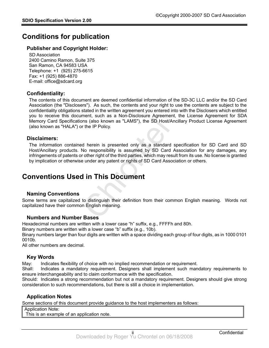
Conventions Used in This Document
Naming Conventions
Some terms are capitalized to distinguish their definition from their common English meaning. Words not
capitalized have their common English meaning.
Numbers and Number Bases
Hexadecimal numbers are written with a lower case “h” suffix, e.g., FFFFh and 80h.
Binary numbers are written with a lower case “b” suffix (e.g., 10b).
Binary numbers larger than four digits are written with a space dividing each group of four digits, as in 1000 0101
0010b.
All other numbers are decimal.
Key Words
Indicates flexibility of choice with no implied recommendation or requirement.
Indicates a mandatory requirement. Designers shall implement such mandatory requirements to
May:
Shall:
ensure interchangeability and to claim conformance with the specification.
Should: Indicates a strong recommendation but not a mandatory requirement. Designers should give strong
consideration to such recommendations, but there is still a choice in implementation.
Application Notes
Some sections of this document provide guidance to the host implementers as follows:
Application Note:
This is an example of an application note.
ii
Confidential
ChrontelDownloaded by Roger Yu Chrontel on 06/18/2008�
SDIO Specification Version 2.00
©Copyright 2000-2007 SD Card Association
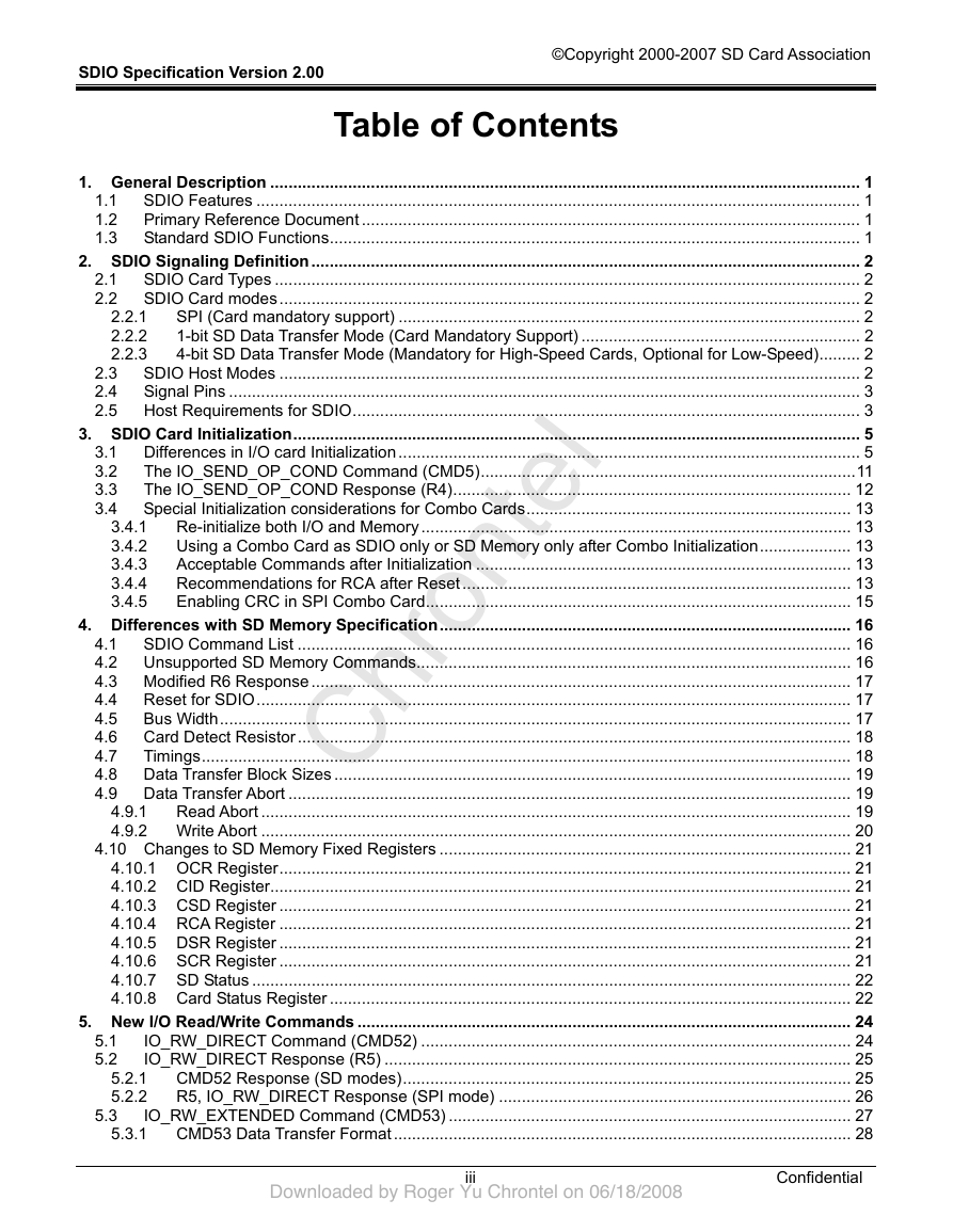
Table of Contents
2.2.1
2.2.2
2.2.3
3.4.1
3.4.2
3.4.3
3.4.4
3.4.5
1. General Description ................................................................................................................................. 1
1.1 SDIO Features .................................................................................................................................... 1
1.2 Primary Reference Document ............................................................................................................. 1
1.3 Standard SDIO Functions.................................................................................................................... 1
2. SDIO Signaling Definition........................................................................................................................ 2
2.1 SDIO Card Types ................................................................................................................................ 2
2.2 SDIO Card modes............................................................................................................................... 2
SPI (Card mandatory support) ..................................................................................................... 2
1-bit SD Data Transfer Mode (Card Mandatory Support) ............................................................. 2
4-bit SD Data Transfer Mode (Mandatory for High-Speed Cards, Optional for Low-Speed)......... 2
2.3 SDIO Host Modes ............................................................................................................................... 2
2.4 Signal Pins .......................................................................................................................................... 3
2.5 Host Requirements for SDIO............................................................................................................... 3
3. SDIO Card Initialization............................................................................................................................ 5
3.1 Differences in I/O card Initialization..................................................................................................... 5
The IO_SEND_OP_COND Command (CMD5)..................................................................................11
3.2
3.3
The IO_SEND_OP_COND Response (R4)....................................................................................... 12
3.4 Special Initialization considerations for Combo Cards....................................................................... 13
Re-initialize both I/O and Memory.............................................................................................. 13
Using a Combo Card as SDIO only or SD Memory only after Combo Initialization.................... 13
Acceptable Commands after Initialization .................................................................................. 13
Recommendations for RCA after Reset ..................................................................................... 13
Enabling CRC in SPI Combo Card............................................................................................. 15
4. Differences with SD Memory Specification.......................................................................................... 16
4.1 SDIO Command List ......................................................................................................................... 16
4.2 Unsupported SD Memory Commands............................................................................................... 16
4.3 Modified R6 Response...................................................................................................................... 17
4.4 Reset for SDIO.................................................................................................................................. 17
4.5 Bus Width.......................................................................................................................................... 17
4.6 Card Detect Resistor......................................................................................................................... 18
4.7
Timings.............................................................................................................................................. 18
4.8 Data Transfer Block Sizes ................................................................................................................. 19
4.9 Data Transfer Abort ........................................................................................................................... 19
4.9.1
Read Abort ................................................................................................................................. 19
4.9.2 Write Abort ................................................................................................................................. 20
4.10 Changes to SD Memory Fixed Registers .......................................................................................... 21
4.10.1 OCR Register............................................................................................................................. 21
4.10.2 CID Register............................................................................................................................... 21
4.10.3 CSD Register ............................................................................................................................. 21
4.10.4 RCA Register ............................................................................................................................. 21
4.10.5 DSR Register ............................................................................................................................. 21
4.10.6 SCR Register ............................................................................................................................. 21
4.10.7 SD Status ................................................................................................................................... 22
4.10.8 Card Status Register .................................................................................................................. 22
5. New I/O Read/Write Commands ............................................................................................................ 24
IO_RW_DIRECT Command (CMD52) .............................................................................................. 24
IO_RW_DIRECT Response (R5) ...................................................................................................... 25
CMD52 Response (SD modes).................................................................................................. 25
R5, IO_RW_DIRECT Response (SPI mode) ............................................................................. 26
IO_RW_EXTENDED Command (CMD53) ........................................................................................ 27
CMD53 Data Transfer Format.................................................................................................... 28
5.1
5.2
5.2.1
5.2.2
5.3.1
5.3
iii
Confidential
ChrontelDownloaded by Roger Yu Chrontel on 06/18/2008�
SDIO Specification Version 2.00
©Copyright 2000-2007 SD Card Association
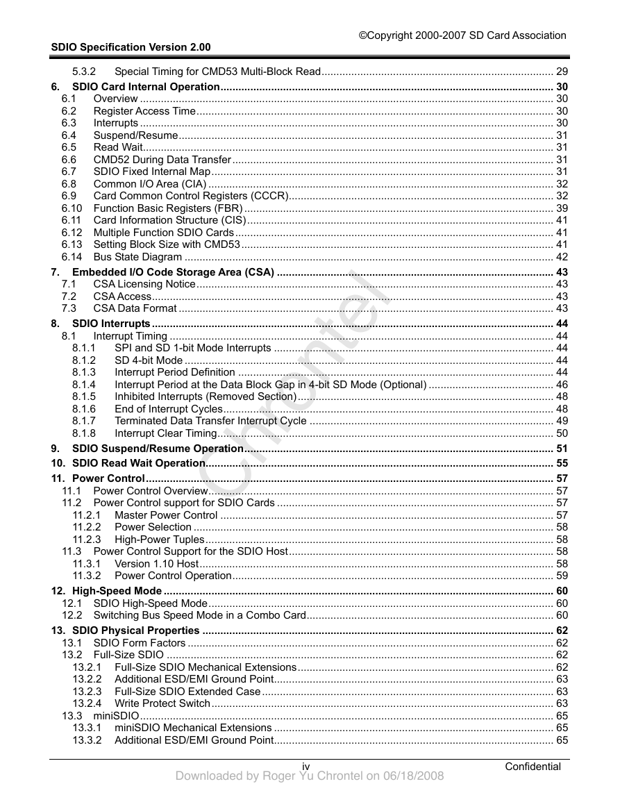
8.1
5.3.2
8.1.1
8.1.2
8.1.3
8.1.4
8.1.5
8.1.6
8.1.7
8.1.8
Special Timing for CMD53 Multi-Block Read.............................................................................. 29
6. SDIO Card Internal Operation................................................................................................................ 30
6.1 Overview ........................................................................................................................................... 30
6.2 Register Access Time........................................................................................................................ 30
6.3
Interrupts ........................................................................................................................................... 30
6.4 Suspend/Resume.............................................................................................................................. 31
6.5 Read Wait.......................................................................................................................................... 31
6.6 CMD52 During Data Transfer............................................................................................................ 31
6.7 SDIO Fixed Internal Map................................................................................................................... 31
6.8 Common I/O Area (CIA) .................................................................................................................... 32
6.9 Card Common Control Registers (CCCR)......................................................................................... 32
6.10 Function Basic Registers (FBR) ........................................................................................................ 39
6.11 Card Information Structure (CIS)....................................................................................................... 41
6.12 Multiple Function SDIO Cards........................................................................................................... 41
6.13 Setting Block Size with CMD53......................................................................................................... 41
6.14 Bus State Diagram ............................................................................................................................ 42
7. Embedded I/O Code Storage Area (CSA) ............................................................................................. 43
7.1 CSA Licensing Notice........................................................................................................................ 43
7.2 CSA Access....................................................................................................................................... 43
7.3 CSA Data Format .............................................................................................................................. 43
8. SDIO Interrupts....................................................................................................................................... 44
Interrupt Timing ................................................................................................................................. 44
SPI and SD 1-bit Mode Interrupts .............................................................................................. 44
SD 4-bit Mode ............................................................................................................................ 44
Interrupt Period Definition .......................................................................................................... 44
Interrupt Period at the Data Block Gap in 4-bit SD Mode (Optional) .......................................... 46
Inhibited Interrupts (Removed Section)...................................................................................... 48
End of Interrupt Cycles............................................................................................................... 48
Terminated Data Transfer Interrupt Cycle .................................................................................. 49
Interrupt Clear Timing................................................................................................................. 50
9. SDIO Suspend/Resume Operation........................................................................................................ 51
10. SDIO Read Wait Operation..................................................................................................................... 55
11. Power Control......................................................................................................................................... 57
11.1 Power Control Overview.................................................................................................................... 57
11.2 Power Control support for SDIO Cards ............................................................................................. 57
11.2.1 Master Power Control ................................................................................................................ 57
11.2.2 Power Selection ......................................................................................................................... 58
11.2.3 High-Power Tuples..................................................................................................................... 58
11.3 Power Control Support for the SDIO Host......................................................................................... 58
11.3.1 Version 1.10 Host....................................................................................................................... 58
11.3.2 Power Control Operation............................................................................................................ 59
12. High-Speed Mode ................................................................................................................................... 60
12.1 SDIO High-Speed Mode.................................................................................................................... 60
12.2 Switching Bus Speed Mode in a Combo Card................................................................................... 60
13. SDIO Physical Properties ...................................................................................................................... 62
13.1 SDIO Form Factors ........................................................................................................................... 62
13.2 Full-Size SDIO .................................................................................................................................. 62
13.2.1 Full-Size SDIO Mechanical Extensions...................................................................................... 62
13.2.2 Additional ESD/EMI Ground Point.............................................................................................. 63
13.2.3 Full-Size SDIO Extended Case.................................................................................................. 63
13.2.4 Write Protect Switch................................................................................................................... 63
13.3 miniSDIO........................................................................................................................................... 65
13.3.1 miniSDIO Mechanical Extensions .............................................................................................. 65
13.3.2 Additional ESD/EMI Ground Point.............................................................................................. 65
iv
Confidential
ChrontelDownloaded by Roger Yu Chrontel on 06/18/2008�
SDIO Specification Version 2.00
©Copyright 2000-2007 SD Card Association
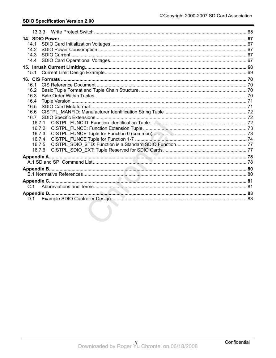
13.3.3 Write Protect Switch................................................................................................................... 65
14. SDIO Power............................................................................................................................................. 67
14.1 SDIO Card Initialization Voltages ...................................................................................................... 67
14.2 SDIO Power Consumption ................................................................................................................ 67
14.3 SDIO Current .................................................................................................................................... 67
14.4 SDIO Card Operational Voltages....................................................................................................... 67
15. Inrush Current Limiting.......................................................................................................................... 68
15.1 Current Limit Design Example........................................................................................................... 69
16. CIS Formats ............................................................................................................................................ 70
16.1 CIS Reference Document ................................................................................................................. 70
16.2 Basic Tuple Format and Tuple Chain Structure ................................................................................. 70
16.3 Byte Order Within Tuples .................................................................................................................. 70
16.4 Tuple Version .................................................................................................................................... 71
16.5 SDIO Card Metaformat...................................................................................................................... 71
16.6 CISTPL_MANFID: Manufacturer Identification String Tuple.............................................................. 72
16.7 SDIO Specific Extensions.................................................................................................................. 72
16.7.1 CISTPL_FUNCID: Function Identification Tuple......................................................................... 72
16.7.2 CISTPL_FUNCE: Function Extension Tuple .............................................................................. 73
16.7.3 CISTPL_FUNCE Tuple for Function 0 (common)....................................................................... 73
16.7.4 CISTPL_FUNCE Tuple for Function 1-7 .................................................................................... 74
16.7.5 CISTPL_SDIO_STD: Function is a Standard SDIO Function..................................................... 77
16.7.6 CISTPL_SDIO_EXT: Tuple Reserved for SDIO Cards............................................................... 77
Appendix A..................................................................................................................................................... 78
A.1 SD and SPI Command List.................................................................................................................... 78
Appendix B..................................................................................................................................................... 80
B.1 Normative References........................................................................................................................... 80
Appendix C..................................................................................................................................................... 81
C.1 Abbreviations and Terms................................................................................................................... 81
Appendix D..................................................................................................................................................... 83
D.1 Example SDIO Controller Design...................................................................................................... 83
v
Confidential
ChrontelDownloaded by Roger Yu Chrontel on 06/18/2008�
SDIO Specification Version 2.00
©Copyright 2000-2007 SD Card Association
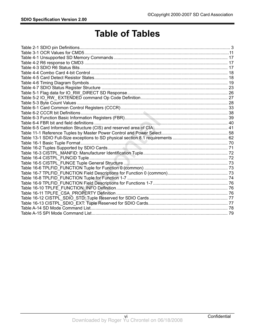
Table of Tables
Table 2-1 SDIO pin Definitions........................................................................................................................... 3
Table 3-1 OCR Values for CMD5......................................................................................................................11
Table 4-1 Unsupported SD Memory Commands ............................................................................................. 17
Table 4-2 R6 response to CMD3 ..................................................................................................................... 17
Table 4-3 SDIO R6 Status Bits......................................................................................................................... 17
Table 4-4 Combo Card 4-bit Control ................................................................................................................ 18
Table 4-5 Card Detect Resistor States............................................................................................................. 18
Table 4-6 Timing Diagram Symbols ................................................................................................................. 19
Table 4-7 SDIO Status Register Structure ....................................................................................................... 23
Table 5-1 Flag data for IO_RW_DIRECT SD Response.................................................................................. 26
Table 5-2 IO_RW_ EXTENDED command Op Code Definition....................................................................... 27
Table 5-3 Byte Count Values ........................................................................................................................... 28
Table 6-1 Card Common Control Registers (CCCR) ....................................................................................... 33
Table 6-2 CCCR bit Definitions........................................................................................................................ 38
Table 6-3 Function Basic Information Registers (FBR).................................................................................... 39
Table 6-4 FBR bit and field definitions ............................................................................................................. 40
Table 6-5 Card Information Structure (CIS) and reserved area of CIA............................................................. 41
Table 11-1 Reference Tuples by Master Power Control and Power Select...................................................... 58
Table 13-1 SDIO Full-Size exceptions to SD physical section 8.1 requirements ............................................. 62
Table 16-1 Basic Tuple Format........................................................................................................................ 70
Table 16-2 Tuples Supported by SDIO Cards.................................................................................................. 71
Table 16-3 CISTPL_MANFID: Manufacturer Identification Tuple..................................................................... 72
Table 16-4 CISTPL_FUNCID Tuple ................................................................................................................. 72
Table 16-5 CISTPL_FUNCE Tuple General Structure ..................................................................................... 73
Table 16-6 TPLFID_FUNCTION Tuple for Function 0 (common) .................................................................... 73
Table 16-7 TPLFID_FUNCTION Field Descriptions for Function 0 (common)................................................. 73
Table 16-8 TPLFID_FUNCTION Tuple for Function 1-7 .................................................................................. 74
Table 16-9 TPLFID_FUNCTION Field Descriptions for Functions 1-7............................................................. 76
Table 16-10 TPLFE_FUNCTION_INFO Definition........................................................................................... 76
Table 16-11 TPLFE_CSA_PROPERTY Definition ........................................................................................... 76
Table 16-12 CISTPL_SDIO_STD: Tuple Reserved for SDIO Cards................................................................ 77
Table 16-13 CISTPL_SDIO_EXT: Tuple Reserved for SDIO Cards................................................................. 77
Table A-14 SD Mode Command List................................................................................................................ 78
Table A-15 SPI Mode Command List............................................................................................................... 79
vi
Confidential
ChrontelDownloaded by Roger Yu Chrontel on 06/18/2008�
SDIO Specification Version 2.00
©Copyright 2000-2007 SD Card Association
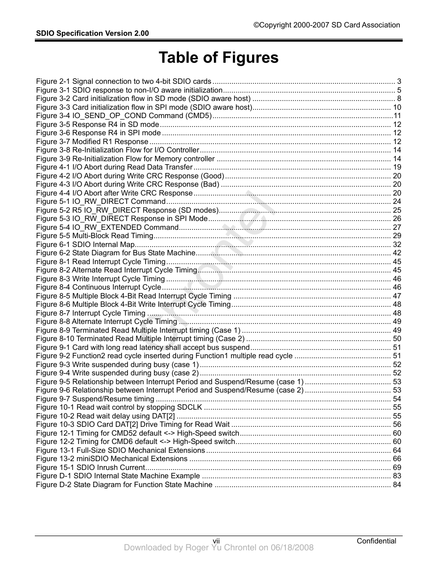
Table of Figures
Figure 2-1 Signal connection to two 4-bit SDIO cards ....................................................................................... 3
Figure 3-1 SDIO response to non-I/O aware initialization.................................................................................. 5
Figure 3-2 Card initialization flow in SD mode (SDIO aware host) .................................................................... 8
Figure 3-3 Card initialization flow in SPI mode (SDIO aware host).................................................................. 10
Figure 3-4 IO_SEND_OP_COND Command (CMD5)......................................................................................11
Figure 3-5 Response R4 in SD mode.............................................................................................................. 12
Figure 3-6 Response R4 in SPI mode ............................................................................................................. 12
Figure 3-7 Modified R1 Response................................................................................................................... 12
Figure 3-8 Re-Initialization Flow for I/O Controller........................................................................................... 14
Figure 3-9 Re-Initialization Flow for Memory controller ................................................................................... 14
Figure 4-1 I/O Abort during Read Data Transfer.............................................................................................. 19
Figure 4-2 I/O Abort during Write CRC Response (Good)............................................................................... 20
Figure 4-3 I/O Abort during Write CRC Response (Bad) ................................................................................. 20
Figure 4-4 I/O Abort after Write CRC Response.............................................................................................. 20
Figure 5-1 IO_RW_DIRECT Command........................................................................................................... 24
Figure 5-2 R5 IO_RW_DIRECT Response (SD modes).................................................................................. 25
Figure 5-3 IO_RW_DIRECT Response in SPI Mode....................................................................................... 26
Figure 5-4 IO_RW_EXTENDED Command..................................................................................................... 27
Figure 5-5 Multi-Block Read Timing................................................................................................................. 29
Figure 6-1 SDIO Internal Map.......................................................................................................................... 32
Figure 6-2 State Diagram for Bus State Machine............................................................................................. 42
Figure 8-1 Read Interrupt Cycle Timing........................................................................................................... 45
Figure 8-2 Alternate Read Interrupt Cycle Timing............................................................................................ 45
Figure 8-3 Write Interrupt Cycle Timing ........................................................................................................... 46
Figure 8-4 Continuous Interrupt Cycle............................................................................................................. 46
Figure 8-5 Multiple Block 4-Bit Read Interrupt Cycle Timing ........................................................................... 47
Figure 8-6 Multiple Block 4-Bit Write Interrupt Cycle Timing............................................................................ 48
Figure 8-7 Interrupt Cycle Timing .................................................................................................................... 48
Figure 8-8 Alternate Interrupt Cycle Timing ..................................................................................................... 49
Figure 8-9 Terminated Read Multiple Interrupt timing (Case 1) ....................................................................... 49
Figure 8-10 Terminated Read Multiple Interrupt timing (Case 2) ..................................................................... 50
Figure 9-1 Card with long read latency shall accept bus suspend................................................................... 51
Figure 9-2 Function2 read cycle inserted during Function1 multiple read cycle .............................................. 51
Figure 9-3 Write suspended during busy (case 1) ........................................................................................... 52
Figure 9-4 Write suspended during busy (case 2) ........................................................................................... 52
Figure 9-5 Relationship between Interrupt Period and Suspend/Resume (case 1) ......................................... 53
Figure 9-6 Relationship between Interrupt Period and Suspend/Resume (case 2) ......................................... 53
Figure 9-7 Suspend/Resume timing ................................................................................................................ 54
Figure 10-1 Read wait control by stopping SDCLK ......................................................................................... 55
Figure 10-2 Read wait delay using DAT[2] ...................................................................................................... 55
Figure 10-3 SDIO Card DAT[2] Drive Timing for Read Wait ............................................................................ 56
Figure 12-1 Timing for CMD52 default <-> High-Speed switch........................................................................ 60
Figure 12-2 Timing for CMD6 default <-> High-Speed switch.......................................................................... 60
Figure 13-1 Full-Size SDIO Mechanical Extensions ........................................................................................ 64
Figure 13-2 miniSDIO Mechanical Extensions ................................................................................................ 66
Figure 15-1 SDIO Inrush Current..................................................................................................................... 69
Figure D-1 SDIO Internal State Machine Example .......................................................................................... 83
Figure D-2 State Diagram for Function State Machine .................................................................................... 84
vii
Confidential
ChrontelDownloaded by Roger Yu Chrontel on 06/18/2008�


 2023年江西萍乡中考道德与法治真题及答案.doc
 2012年重庆南川中考生物真题及答案.doc
 2013年江西师范大学地理学综合及文艺理论基础考研真题.doc
 2020年四川甘孜小升初语文真题及答案I卷.doc
 2020年注册岩土工程师专业基础考试真题及答案.doc
 2023-2024学年福建省厦门市九年级上学期数学月考试题及答案.doc
 2021-2022学年辽宁省沈阳市大东区九年级上学期语文期末试题及答案.doc
 2022-2023学年北京东城区初三第一学期物理期末试卷及答案.doc
 2018上半年江西教师资格初中地理学科知识与教学能力真题及答案.doc
 2012年河北国家公务员申论考试真题及答案-省级.doc
 2020-2021学年江苏省扬州市江都区邵樊片九年级上学期数学第一次质量检测试题及答案.doc
 2022下半年黑龙江教师资格证中学综合素质真题及答案.doc