Computer-ControlledSystems
Third Edition
SolutionsManual
Karl J. Åström
Björn Wittenmark
Department of Automatic Control
Lund Institute of Technology
October 1997
�
Preface
This Solutions Manual contains solutions to most of the problems in the third
edition of
Åström, K. J. and B. Wittenmark H1997I: Computer controlled Systems –
Theory and Applications, Prentice Hall Inc., Englewood Cliffs, N. J.
Many of the problems are intentionally made such that the students have to
use a simulation program to verify the analytical solutions. This is important
since it gives a feeling for the relation between the pulse transfer function and
the time domain. In the book and the solutions we have used Matlab/Simulink.
Information about macros used to generate the illustrations can be obtained by
writing to us.
It is also important that a course in digital control includes laboratory exercises.
The contents in the laboratory experiments are of course dependent on the avail-
able equipment. Examples of experiments are
P
P
P
Illustration of aliasing
Comparison between continuous time and discrete time controllers
State feedback control. Redesign of continuous time controllers as well as
controllers based on discrete time synthesis
Controllers based on input-output design
Control of systems subject to stochastic disturbances.
P
P
Finally we would like to thank collegues and students who have helped us to test
the book and the solutions.
Karl J. Åström
Björn Wittenmark
Department of Automatic Control
Lund Institute of Technology
Box 118
S-220 00 Lund, Sweden
i
�
Solutions to Chapter 2
Problem 2.1
The system is described by
−ax bu
Sampling the system using H2.4I and H2.5I gives
˙x
y cx
xHkh hI e−
ahxHkhI
yHkhI cxHkhI
ah
1 − e−
uHkhI
b
a
The pole of the sampled system is expH
−ahI. The pole is real. For small values
of h the pole is close to 1. If a 0 then the pole moves towards the origin when
h increases. If a 0 then the pole moves along the positive real axis.
Problem 2.2
a. Using the Laplace transform method we find that
9>>;!
1
−
1
9>>;
8>>: cos h sin h
sI − A
9>>; ds
8>>: sin s
hZ
hZ
− sin h cos h
eAsB ds
L−
1
cos s
0
0
1
−1 s
1
s2 1
8>>: s
9>>;
8>>: 1 − cos h
sin h
F eAh L−
G
b. The system has the transfer function
GHsI
s 3
s2 3s 2
Using the Table 2.1 gives
HHqI 2
c. One state space realization of the system is
s 3
2
2h
2h
h
h −
1 − e−
q − e−
Hs 1IHs 2I 2
s 1 −
1 − e−
q − e−
8>>>>>>>: 0 0 0
9>>>>>>>; x
8>>>>>>>: 1
9>>>>>>>; u
9; x
8: 0 0 1
9>>>>>>>; A3 0
8>>>>>>>: 0 0 0
1 0 0
0 1 0
0
0
0 0 0
1 0 0
1
s 2
1
˙x
y
Now
A2
�
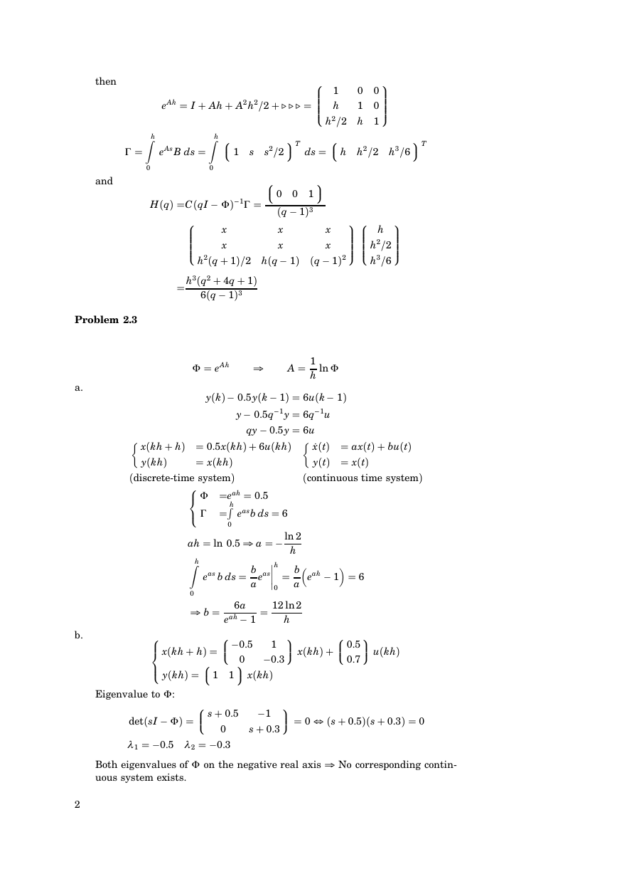
then
and
hZ
0
G
9;T
ds
0 0
1 0
h
h2/2 h 1
8>>>>>>>: 1
9>>>>>>>;
8: h h2/2 h3/6
9;
9>>>>>>>;
8>>>>>>>: h
9>>>>>>>;
x
x
h2/2
h3/6
Hq − 1I2
s2/2
9;T
8: 0 0 1
Hq − 1I3
x
x
eAh I Ah A2h2/2 (((
8: 1 s
hZ
0
eAsB ds
HHqI CHqI −
1G
I−
8>>>>>>>:
x
x
h3Hq2 4q 1I
h2Hq 1I/2 hHq − 1I
6Hq − 1I3
Problem 2.3
F eAh
yHkI
A 1
h
ln F
− 0.5yHk − 1I 6uHk − 1I
1y 6q−
y − 0.5q−
1u
qy − 0.5y 6u
xHkh hI 0.5xHkhI 6uHkhI
yHkhI
xHkhI
Hdiscrete-time systemI
˙xHtI axHtI buHtI
yHtI xHtI
Hcontinuous time systemI
easb ds 6
0
a
hR
eah 0.5
eas b ds b
a
8<: F
hZ
ah ln 0.5
8>>: −0.5
8><>: xHkh hI
9; xHkhI
8: 1 1
8>>: s 0.5
b 6a
− 1
eah
yHkhI
:
eas
0
0
6
eah
− 1
h
ln 2
−
h
b
a
12 ln 2
0
1
−0.3
h
9>>; xHkhI
9>>; 0
−1
s 0.3
8>>: 0.5
0.7
9>>; uHkhI
Eigenvalue to F
detHsI −
l 1
I
−0.5 l 2
Both eigenvalues of F
uous system exists.
Hs 0.5IHs 0.3I 0
0
−0.3
on the negative real axis No corresponding contin-
a.
b.
2
F
G
F
�
c.
yHkI 0.5yHk − 1I 6uHk − 1I
yHk 1I
HHqI
−0.5yHkI 6uHtI
q 0.5
6
one pole on the negative real axis.
No equivalent continuous system exists.
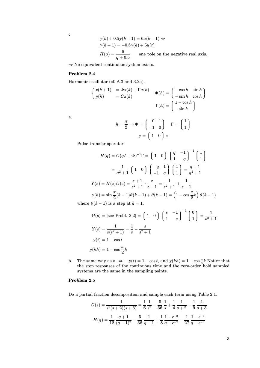
Problem 2.4
Harmonic oscillator Hcf. A.3 and 3.2aI.
xHk 1I F xHkI G uHkI
yHkI
C xHkI
a.
Pulse transfer operator
1
h p
2
9>>;
HhI
−1 0
G HhI
y
− sin h cos h
sin h
8>>: cos h sin h
8>>: 1 − cos h
9>>;
9>>; G
8>>: 1
9>>;
8>>: 0 1
9; x
8: 1 0
9>>;−
9;8>>: q −1
18>>: 1
8: 1 0
9>>; q 1
9>>;8>>: 1
9;8>>: q 1
q2 1
1
1
1
z2 1
z − 1
p
Hk − 1Iq Hk − 1I q Hk − 1I
q Hk − 1I
1 − cos
9>>; 1
9;8>>: s −1
2
9>>;−
18>>: 0
8: 1 0
z
z − 1
1G
I−
−1 q
9>>;
1
1
q
k
1
s
1
s2 1
1
HHqI CHqI −
q2 1
8: 1 0
YHzI HHzIUHzI z 1
z2 1
yHkI sin
p
2
where q Hk − 1I is a step at k 1.
GHsI Jsee Probl. 2.2K
sHs2 1I 1
s −
s
s2 1
1
YHsI
yHtI 1 − cos t
yHkhI 1 − cos
b. The same way as a.
p
2
k
4 k Notice that
the step responses of the continuous time and the zero-order hold sampled
systems are the same in the sampling points.
yHtI 1 − cos t, and yHkhI 1 − cos p
Problem 2.5
Do a partial fraction decomposition and sample each term using Table 2.1:
GHsI
1
s2Hs 2IHs 3I 1
6
1
s2 −
HHqI 1
12
q 1
Hq − 1I2 −
5
36
1
q − 1
5
36
1
8
1
1
4
s
1 − e−
q − e−
1
s 2 −
1
27
2
2 −
1
1
s 3
9
1 − e−
q − e−
3
3
3
F
F
F
�
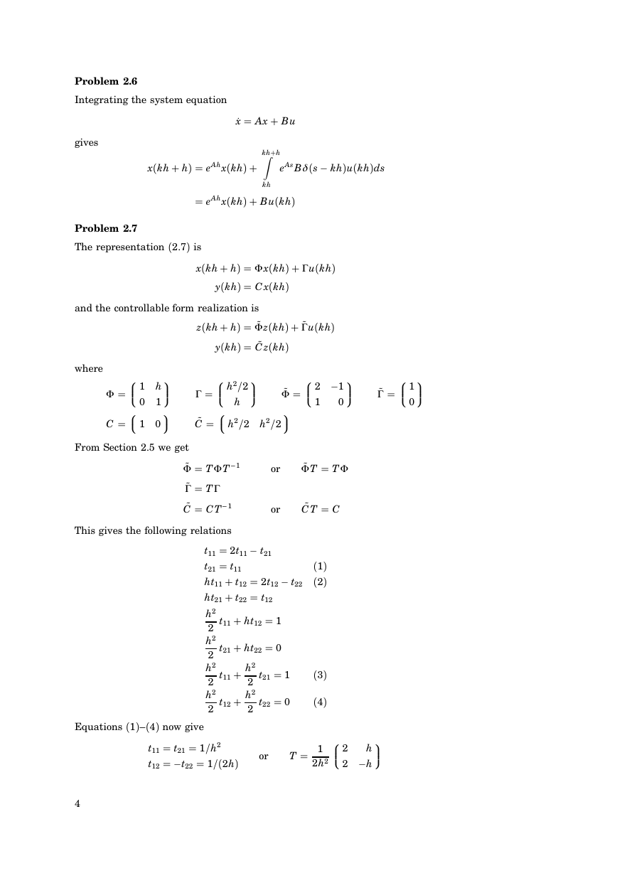
Problem 2.6
Integrating the system equation
gives
˙x Ax Bu
khhZ
eAsBd Hs − khIuHkhIds
xHkh hI eAhxHkhI
kh
eAhxHkhI BuHkhI
Problem 2.7
The representation H2.7I is
xHkh hI F xHkhI G uHkhI
yHkhI C xHkhI
and the controllable form realization is
zHkh hI ˜F zHkhI ˜G uHkhI
where
8>>: 1 h
8: 1 0
0 1
9>>;
9;
F
C
G
˜C
From Section 2.5 we get
yHkhI ˜C zHkhI
8>>: h2/2
9>>;
8: h2/2 h2/2
h
˜F
9;
8>>: 2 −1
1
0
9>>;
9>>;
8>>: 1
0
˜G
1
˜F TF T −
˜G TG
˜C CT −
This gives the following relations
1
or
or
˜F T TF
˜C T C
t11 2t11 − t21
t21 t11
ht11 t12 2t12 − t22
ht21 t22 t12
t11 ht12 1
h2
2
t21 ht22 0
h2
2
t21 1
t11 h2
h2
2
2
t12 h2
t22 0
h2
2
2
H1I
H2I
H3I
H4I
Equations H1I–H4I now give
t11 t21 1/h2
t12
−t22 1/H2hI
or
T 1
2h2
4
9>>;
8>>: 2
h
2 −h
�
8>>: z
− 0.2
0 z − 0.5
9>>;8>>: 2
1
9>>;
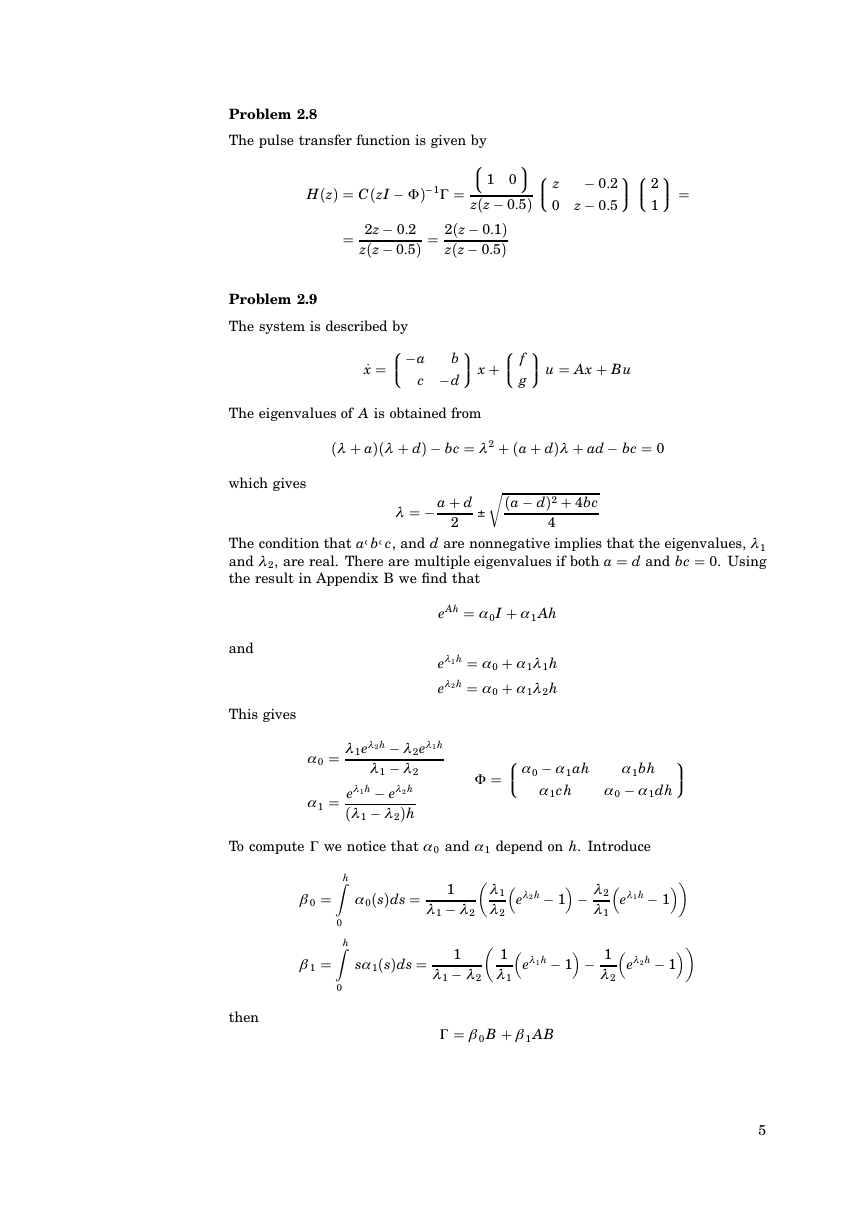
Problem 2.8
The pulse transfer function is given by
1G
I−
8: 1 0
9;
HHzI CHzI −
zHz − 0.5I
zHz − 0.5I 2Hz − 0.1I
2z − 0.2
zHz − 0.5I
8>>: f
9>>; x
8>>: −a
˙x
b
c −d
Problem 2.9
The system is described by
9>>; u Ax Bu
g
The eigenvalues of A is obtained from
Hl aIHl dI
which gives
l
r
− bc l 2 Ha dIl ad − bc 0
a d
2
Ha − dI2 4bc
4
−
The condition that aA bA c, and d are nonnegative implies that the eigenvalues, l 1
and l 2, are real. There are multiple eigenvalues if both a d and bc 0. Using
the result in Appendix B we find that
eAh a 0I a 1 Ah
el 1h a 0 a 1l 1h
el 2h a 0 a 1l 2h
and
This gives
To compute G we notice that a 0 and a 1 depend on h. Introduce
l 2el 1h
a 0 l 1el 2h
−
l 2
l 1 −
− el 2h
a 1 el 1h
l 2Ih
Hl 1 −
hZ
hZ
a 0HsIds
0
b 0
b 1
sa 1HsIds
l 1
l 2
1
l 1 −
l 2
1
l 1 −
l 2
8>>:a 0 −
a 1ah
a 1ch
F
a 1bh
a 1dh
a 0 −
el 2h
− 1
−
l 2
l 1
el 1h
− 1
1
l 1
el 1h
− 1
−
1
l 2
el 2h
9>>;
0
then
G b 0 B b 1 AB
− 1
5
F
–
�
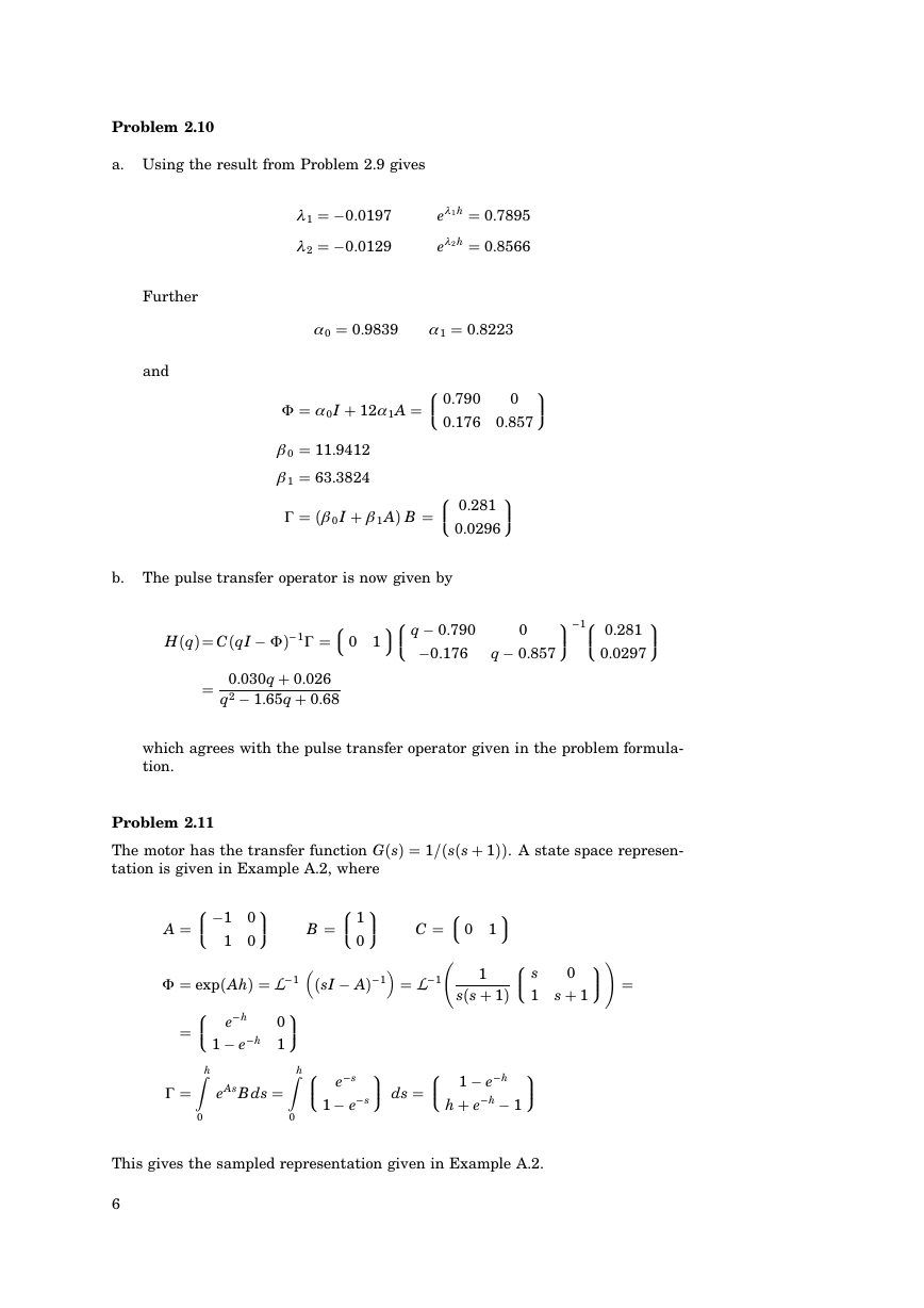
Problem 2.10
a. Using the result from Problem 2.9 gives
l 1
l 2
−0.0197
−0.0129
el 1h 0.7895
el 2h 0.8566
Further
and
a 0 0.9839
9>>;
0.176 0.857
a 1 0.8223
8>>: 0.790
8>>: 0.281
0.0296
0
9>>;
F a 0I 12a 1A
b 0 11.9412
b 1 63.3824
G Hb 0 I b 1 AI B
b. The pulse transfer operator is now given by
8: 0 1
9;8>>: q − 0.790
−0.176
9>>;−
18>>: 0.281
0.0297
9>>;
0
q − 0.857
HHqI CHqI −
1G
I−
0.030q 0.026
− 1.65q 0.68
q2
which agrees with the pulse transfer operator given in the problem formula-
tion.
Problem 2.11
The motor has the transfer function GHsI 1/HsHs 1II. A state space represen-
tation is given in Example A.2, where
1
A
9>>;
1 0
8>>: −1 0
8>>: e−
hZ
h
1
9>>;
F expHAhI L−
0
hZ
h 1
1 − e−
eAsBds
G
0
0
0
B
8>>: 1
9>>;
HsI − AI−
8>>: e−
s
s
1 − e−
9;
8: 0 1
C
L−
1
1
sHs 1I
0
1 s 1
9>>;!
8>>: s
9>>;
9>>; ds
8>>: 1 − e−
h e−
h
h
− 1
This gives the sampled representation given in Example A.2.
6
F
�




 2023年江西萍乡中考道德与法治真题及答案.doc
 2012年重庆南川中考生物真题及答案.doc
 2013年江西师范大学地理学综合及文艺理论基础考研真题.doc
 2020年四川甘孜小升初语文真题及答案I卷.doc
 2020年注册岩土工程师专业基础考试真题及答案.doc
 2023-2024学年福建省厦门市九年级上学期数学月考试题及答案.doc
 2021-2022学年辽宁省沈阳市大东区九年级上学期语文期末试题及答案.doc
 2022-2023学年北京东城区初三第一学期物理期末试卷及答案.doc
 2018上半年江西教师资格初中地理学科知识与教学能力真题及答案.doc
 2012年河北国家公务员申论考试真题及答案-省级.doc
 2020-2021学年江苏省扬州市江都区邵樊片九年级上学期数学第一次质量检测试题及答案.doc
 2022下半年黑龙江教师资格证中学综合素质真题及答案.doc