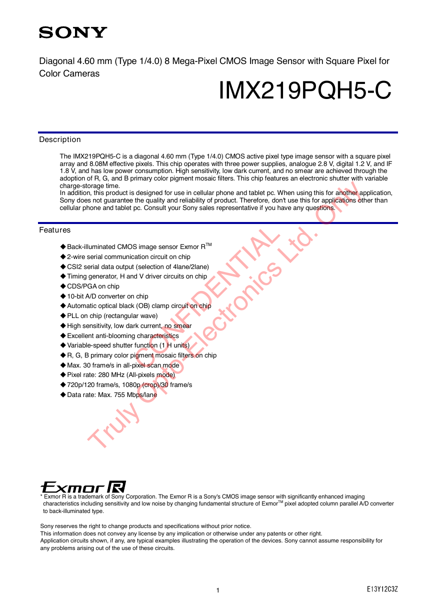
Description
Features
Device Structure
USE RESTRICTION NOTICE
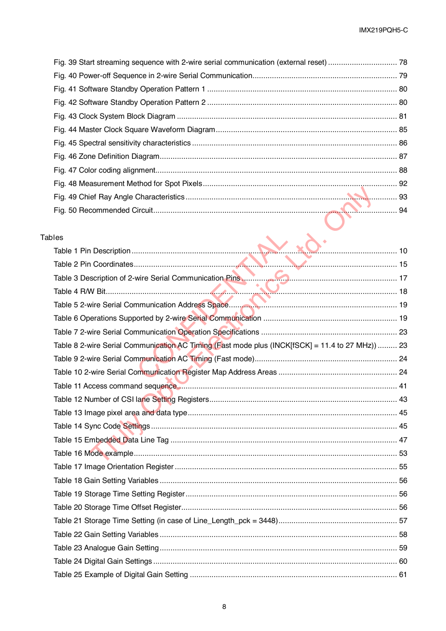
1. Block Diagram and Pin Configuration
1-1 Block Diagram
1-2 Pin Description
1-3 Pin Equivalent Circuit
1-4 Chip Center, Optical Center and Pin Assignment
1-5 Pin Coordinates
2. Pixel Signal Output Specifications
2-1 CSI-2 Signalling Mode
2-1-1 MIPI Transmitter
3. Control Registers
3-1 2-wire Serial Communication Operation Specifications
3-1-1 Communication Protocol
3-1-2 2-wire serial communication read/write operation supported
3-1-3 2-wire serial communication block characteristics
3-1-4 2-wire serial communication register map
3-1-5 Register Synchronization (Frame Bank )
3-2 2-wire Serial Communication Register Map (Configuration register, Parameter limit register)
3-2-1 Configuration Registers – [0x0000-0x0FFF]
3-2-2 Set-up Registers – [0x0100-0x0147]
3-2-3 Frame Bank Control and Group “A” – [0x0150-0x018D]
3-2-4 Frame Bank Control Group “B” – [0x0254-0x028D]
3-2-5 Set-up Registers – [0x0300-0x0627]
3-3 Parameter Limit Registers – [0x1000-0x1FFF] (Read Only and Static)
3-3-1 Integration Time and Gain Parameter Limit Registers – [0x1000-0x1301]
3-4 Manufacturer Specific Registers – [0x3000-0x5FFF ]
4. Output Data Format
4-1 CSI-2 Output Data Format
4-1-1 CSI-2 Output Data Channels
4-1-2 CSI-2 Frame Structure
4-1-3 Short Packet & Long Packet
4-1-4 Data type
4-1-5 CSI-2 Frame Format
4-1-6 CSI-2 Embedded Data Line
5. Setting Required for Imaging
5-1 Pixel Array Physical Image
5-2 Pixel Binning Mode
5-3 image size
5-4 Readout Position
5-5 Frame Rate Calculation Formula
5-6 Black Level Control
5-7 Storage Time (Electronic Shutter) Settings
5-7-1 Storage Time (Electronic Shutter) Setting Registers
5-7-2 Storage Time Calculation Method
5-8 Gain Settings
5-8-1 Analogue Gain Settings
5-8-2 Digital gain settings
6. On Chip Image Processing
6-1 Test Pattern Generator
6-1-1 Test Pattern
6-2 Digital Gain Setting
6-3 Black Level Adjust
6-4 Defect Correction
6-5 Pixel Re-alignment H Direction
6-6 Pixel Re-alignment V Direction
7. NVM Memory Map
7-1 Block Diagram
7-2 NVM Functions
7-3 Related Registers
7-4 NVM Memory Map
7-5 Defects Address registration
7-5-1 Single defect address
7-5-2 Same Color Adjoining defect address
7-5-3 2x4 defect address
7-5-4 Example Setting
8. How to operate IMX219PQH5-C
8-1 Power on sequence
8-2 Power off sequence
9. Other Functions
9-1 Clock System
9-1-1 Clock Structure
9-1-2 EXCK_FREQ setting depend on INCK frequency
9-2 Clock Setting Example
9-3 Temperature Sensor
10. Electrical Characteristics
10-1 Absolute Maximum Ratings
10-2 Recommended Operating Conditions
10-3 AC Characteristics
10-3-1 Master Clock Waveform Diagram
10-4 Electrical Characteristics
11. Spectral Sensitivity Characteristic
12. Image Sensor Characteristics
12-1 Image Sensor Characteristics
12-2 Zone Definition used for specifying image sensor characteristics
13. Measurement Method for Image Sensor Characteristics
13-1 Measurement conditions
13-2 Color Coding of This Image Sensor and Readout
13-3 Definition of Standard Imaging Conditions
13-4 Measurement method
14. Spot Pixel Specification
15. Notice on White Pixels Specifications
15-1 Measurement Method for Spot Pixels
15-2 Spot Pixel Pattern Specifications
16. Chief Ray Angle Characteristics
17. Connection Example


 2023年江西萍乡中考道德与法治真题及答案.doc
 2012年重庆南川中考生物真题及答案.doc
 2013年江西师范大学地理学综合及文艺理论基础考研真题.doc
 2020年四川甘孜小升初语文真题及答案I卷.doc
 2020年注册岩土工程师专业基础考试真题及答案.doc
 2023-2024学年福建省厦门市九年级上学期数学月考试题及答案.doc
 2021-2022学年辽宁省沈阳市大东区九年级上学期语文期末试题及答案.doc
 2022-2023学年北京东城区初三第一学期物理期末试卷及答案.doc
 2018上半年江西教师资格初中地理学科知识与教学能力真题及答案.doc
 2012年河北国家公务员申论考试真题及答案-省级.doc
 2020-2021学年江苏省扬州市江都区邵樊片九年级上学期数学第一次质量检测试题及答案.doc
 2022下半年黑龙江教师资格证中学综合素质真题及答案.doc